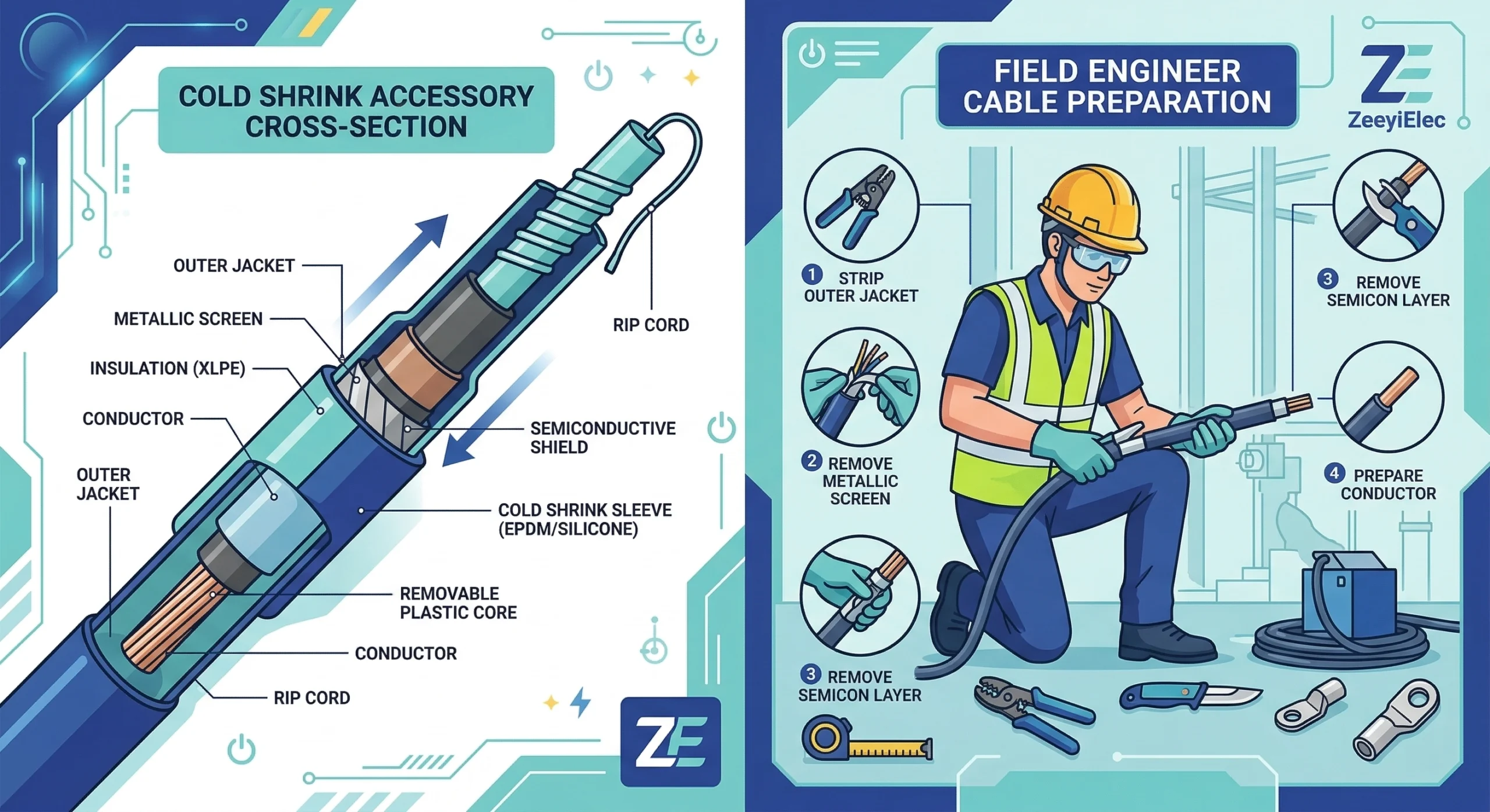
Figure 1: Cross-sectional diagram of a cold shrink cable termination illustrating the pre-expanded silicone body and internal stress control tube.
A cold shrink termination is a pre-expanded, tubular elastomeric sleeve engineered to provide primary dielectric insulation, electric field stress relief, and environmental sealing at the exposed ends of medium-voltage (MV) and high-voltage (HV) power cables. Unlike heat shrink technologies that require a thermal source to activate the material, cold shrink components are factory-expanded and loaded onto a removable, coiled plastic cylinder. Upon unwinding this inner core, the silicone rubber collapses, utilizing its inherent elastic memory to create a permanent, active radial pressure against the cable interface.
The Physics of Elastic Memory
The core performance of these relies heavily on the physical properties of Liquid Silicone Rubber (LSR) or highly formulated EPDM. During manufacturing, the elastomeric body is stretched to approximately 200% to 250% of its relaxed internal diameter. Once deployed in the field, the material strives to return to its original dimensions. Because the target cable diameter is deliberately chosen to be larger than the accessory’s fully relaxed state, the termination exerts a continuous compressive force.
This sustained radial pressure—typically measuring ≥ 0.08 MPa at the cable interface—ensures a tight, void-free contact and prevents moisture ingress throughout the intended service life of the installation. Furthermore, premium silicone formulations must maintain this mechanical grip while withstanding continuous conductor operating temperatures up to 90°C and short-circuit emergency overload conditions reaching 250°C without losing elasticity.
Dielectric Field Management
Beyond physical sealing, the termination must manage the severe electrical stresses that occur where the cable’s factory-extruded insulation screen is cut back. Without proper mitigation, the electric field concentration at this cutback edge would rapidly exceed the dielectric breakdown strength of the surrounding air, leading to localized partial discharge, tracking, and eventual flashover.
Cold shrink terminations address this by integrating either high-permittivity (high-K) refractive stress control tubes or geometric stress cones directly into the molded silicone body. To ensure long-term reliability and insulation integrity under these localized stresses, modern termination structures are rigorously tested and verified against industry frameworks. [NEED AUTHORITY LINK SOURCE] (Suggested anchor: IEC 60502-4 standard for power cable accessories).
[Expert Insight: Material Selection Realities]
LSR vs. EPDM: Liquid Silicone Rubber (LSR) generally offers superior UV and tracking resistance for highly polluted outdoor environments, while EPDM can provide slightly higher mechanical puncture resistance for rugged industrial sites.
Active Pressure Shelf Life: Always check the manufacturing date before installation. Pre-expanded accessories stored above 40°C for over 18 to 24 months may lose a fraction of their permanent set recovery, which can lead to a loose fit and eventual moisture ingress.
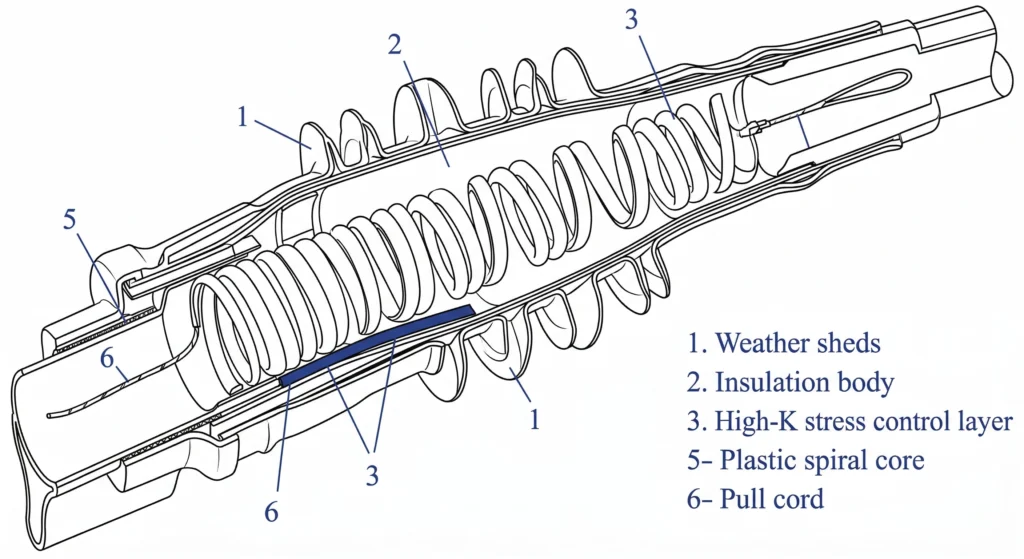
Internal Structure and Dielectric Components
A pre-expanded cold shrink termination is not a homogeneous tube; it is a highly engineered composite system designed to restore insulation integrity and provide robust environmental sealing at vulnerable cable interfaces. To achieve a 25-to-40-year service life, these must integrate three distinct functional layers into a single deployable unit.
Stress Control Mechanism
When the grounded semi-conductive screen of a power cable is removed, the electric field lines concentrate heavily at the cutback edge. To prevent localized dielectric breakdown of the surrounding air, cold shrink terminations employ a refractive stress control method. This involves an inner layer of specially formulated elastomeric material—either co-extruded or molded directly inside the main termination body.
This stress control tube features a high relative permittivity (typically K = 15 to 25) and must maintain a stable volume resistivity of ≥ 1010 Ω·cm. By refracting the high-frequency electric field lines away from the localized cutback area, it limits the maximum surface voltage gradient to ≤ 2.5 kV/mm, ensuring long-term compliance with international testing frameworks such as IEC 60502-4.
Outer Insulation and Tracking Resistance
The primary exterior body is formulated from liquid silicone rubber (LSR), specifically modified to resist electrical tracking, UV degradation, and extreme environmental weathering. A paramount material property of silicone in this application is its dynamic hydrophobicity. When exposed to rain or heavy condensation in outdoor environments, the surface energy forces water to bead up and roll off rather than forming a continuous, conductive water film. Under severe pollution conditions, if surface leakage currents lead to dry band arcing, the silicone formulation must physically resist degradation, a characteristic verified through specialized material testing [VERIFY STANDARD: IEC 60587 tracking and erosion resistance at 4.5 kV for 6 hours].
Environmental Sealing Mastics
While the cold shrink body provides the primary active radial pressure, field installations require supplementary sealing compounds to guarantee complete moisture ingress protection. Installers apply high-tack, self-amalgamating silicone or butyl mastics at two critical junction points: the top metallic lug interface and the bottom extruded cable oversheath. Field experience dictates that wrapping this mastic with absolute precision is strictly required; trapping even a microscopic air void near the semi-conductive screen step can trigger internal partial discharge. These mastics act as an impermeable moisture barrier while simultaneously serving as a pliable buffer during sudden thermal load cycles.
Pre-Installation: Cable Preparation Tolerances
Field data consistently shows that proper accessory selection accounts for only part of the reliability equation; execution during installation carries equal or greater weight. A cold shrink termination will inevitably fail if the underlying medium-voltage cable is improperly prepared. The following preparatory steps dictate the critical dimensional tolerances and handling procedures required before the elastomeric body is ever deployed.
Jacket Removal and Shield Treatment
The initial phase involves removing the outer polymeric jacket and exposing the metallic shield. Depending on the system voltage class, the jacket cutback dimension typically ranges from 250 mm to 450 mm. Installers must carefully secure the copper wire or tape shield, folding it back and temporarily binding it out of the way to prevent contamination of the underlying layers. Any jagged edges or sharp points left on the metallic shield must be smoothed to prevent mechanical puncture of the mastic seals or the inner bore of the termination body.
Semi-Conductive Layer Scoring
Removing the extruded semi-conductive screen is the most critical and error-prone step in the entire preparation sequence. Field experience dictates that this layer cannot simply be sliced through to the core.
Installers must use a precisely calibrated scoring tool to create a spiral or longitudinal groove, intentionally leaving a microscopic layer of the semi-conductive material intact to be peeled by hand. If the blade penetrates too deeply and nicks the underlying XLPE insulation by even ≥ 0.1 mm, it creates an irreversible, high-stress localized defect. Under operating conditions, this microscopic geometry magnifies the localized electric field (often expressed as an elevated ΔE), initiating partial discharge that will eventually bore through the insulation wall.
Insulation Cleaning and Polishing
Once the semi-conductive layer is manually peeled away, the exposed XLPE dielectric must be rendered entirely pristine. Installers must polish the insulation surface using non-conductive aluminum oxide abrasive tape (typically 120-grit followed by 240-grit) to eliminate any ridges, steps, or residual carbon indentations at the semi-con screen boundary.
Cleaning must be performed using approved, rapid-evaporating, lint-free solvent wipes. The wiping motion is governed by a strict field rule: always wipe from the clean end of the insulation down toward the remaining semi-conductive screen. Reversing this direction risks dragging conductive carbon particles back onto the prepared dielectric surface, which creates invisible, microscopic tracking paths. Following a structured during these preparatory steps helps identify these fatal defects before energization.
[Expert Insight: Field Preparation Diagnostics]
The “Fingernail Test”: After removing the semi-con layer, drag your fingernail lightly across the transition step to the XLPE insulation. If your nail catches aggressively, the transition is too abrupt and will cause an unwanted electric field concentration. It must be polished down smoothly.
Solvent Flash-Off: Never slide the termination body over the cable while the insulation is still wet with cleaning solvent. Trapped volatile organic compounds (VOCs) under the silicone will drastically reduce the internal dielectric strength and cause premature breakdown.
The Cold Shrink Installation Sequence (Step-by-Step)
Once the cable is fully prepared and polished, the actual deployment of the elastomeric accessory begins. Unlike heat shrink technologies that require open flames and careful thermal management in the trench or bucket truck, this sequence relies entirely on mechanical potential energy and strict procedural adherence.
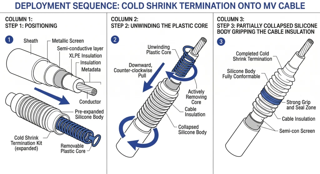
Figure 2: The installation sequence highlighting the critical counter-clockwise extraction of the plastic spiral core.
Positioning the Termination Body
The pre-expanded silicone body is carefully slid over the prepared cable end. Total accuracy during this initial alignment phase is mandatory. Field installers must position the base of the termination at a highly specific distance from the jacket cutback—typically 10 mm to 25 mm, dictated by the manufacturer’s dimensional template. Because the silicone collapses with immense active radial pressure, repositioning the accessory after the shrink process begins is physically impossible without tearing the internal stress control mastic or damaging the semi-conductive overlap.
Unwinding the Spiral Core
The core extraction dynamics dictate a smooth, continuous motion to prevent structural defects. The installer grasps the loose end of the plastic spiral ribbon protruding from the bottom of the tubular body. By pulling this ribbon counter-clockwise, the core begins to separate along its perforations, allowing the expanded silicone to collapse progressively from the bottom up.
Installers must keep the pulling axis strictly parallel to the cable. If the pull angle exceeds 30° from the cable center line, the plastic ribbon experiences severe shear stress and can jam or snap mid-installation. A snapped core effectively halts the process and will often ruin a high-value termination kit, requiring the crew to carefully cut off the partially shrunk accessory and start the entire process over with a new unit.
Final Grounding and Sealing
After the termination body fully collapses over the insulation and the connector lug, the installation transitions to securing the environmental and electrical interfaces.
Grounding continuity is established by folding the copper tape or wire shield back over the semi-conductive layer and securing it with a constant force spring. This mechanical connection must ensure that the interface contact resistance remains ≤ 50 μΩ, effectively managing transient fault currents without localized overheating. To complete the sequence, specialized self-amalgamating mastics are wrapped tightly over the lug barrel and the lower jacket cutback, forming a definitive barrier against moisture ingress in harsh field environments.
Quality Control and Post-Installation Checks
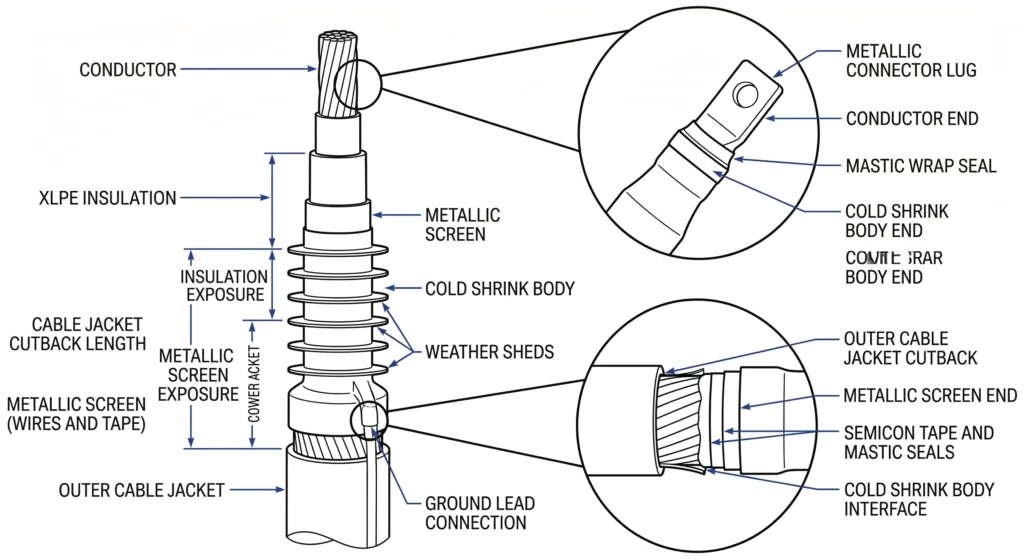
Figure 3: Post-installation visual inspection criteria focusing on the critical jacket cutback overlap and mastic sealing zones.
A completed installation must never be energized without rigorous verification. Systematic field diagnosis isolates root causes before repeat failures occur, but identifying and correcting defects before energizing the circuit is far more economical. By following a structured quality control workflow, field engineers can ensure that the accessory will perform safely under full load conditions.
Visual Inspection Criteria
The immediate post-installation check relies on strict visual and dimensional verification. Installers must first verify the overlap dimensions at both the top and bottom of the accessory. The silicone body must overlap the lower cable jacket by a minimum of 25 mm to 35 mm to ensure an adequate environmental moisture seal. At the top interface, the termination must securely cover the mastic applied over the connector lug barrel without over-stretching the material.
The termination body must also appear entirely concentric around the cable axis. Any localized bulging indicates trapped air, a folded copper tape shield, or improperly wrapped mastic tape. Additionally, a slight, uniform squeeze-out of the sealing mastic at the very edges of the silicone tube is a positive visual indicator that active radial pressure is compressing the seal correctly.
Common Installation Errors to Avoid
Field data indicates that a significant percentage of premature breakdowns are tied directly to execution errors rather than manufacturing defects. For instance, a 15 kV cold shrink termination fails at month fourteen often not because of a faulty silicone batch, but due to microscopic carbon contaminants left on the XLPE insulation or a severely nicked semi-conductive layer during the preparation phase.
Another frequent field error involves failing to seal the terminal lug adequately, allowing rain or ambient humidity to wick down into the stranded conductor core over time. To prevent these recurring issues, utility crews and contractors should leverage systematic diagnostic cross-referencing against known field failure modes.
While visual checks are essential, confirming dielectric integrity often requires offline diagnostic testing prior to commissioning. Field engineers typically perform Very Low Frequency (VLF) withstand testing combined with partial discharge (PD) measurements. A mechanically sound, defect-free cold shrink termination should reliably exhibit a PD level of ≤ 5 pC when subjected to a phase-to-ground test voltage of 1.73 U0. If PD levels exceed this threshold, or if the localized contact resistance at the grounding interface measures ≥ 100 μΩ, it strongly indicates an internal void, a compromised stress control layer, or a poor shield connection that visual inspection alone could not detect.
Engineering Support for Cable Accessory Projects
Specifying the correct cold shrink termination requires matching project parameters far beyond basic voltage class. Incomplete specifications account for a significant percentage of accessory mismatches, triggering procurement delays and potential field failures. Whether your project involves a standard 15 kV indoor switchgear connection or a highly polluted 35 kV outdoor pole-top installation, rigorous technical validation is the first step toward long-term network reliability.
When preparing your procurement documentation, engineers must cross-reference cable datasheets against accessory capabilities. Critical selection parameters include the precise insulation diameter range, the required minimum creepage distance (often specified as ≥ 31 mm/kV for heavy pollution environments), and the conductor cross-section, which typically spans from 50 mm² up to 630 mm² for distribution networks. Failing to align these variables with the physical expansion limits of the silicone body will result in inadequate radial pressure or dielectric breakdown.
To streamline this specification process and eliminate guesswork, engineering teams can utilize a structured to ensure all vital technical data points are captured before submission. For direct support on project-specific model matching, OEM/ODM configurations, or export documentation requirements, reach out to our engineering team to . ZeeyiElec provides fast technical responses and precise quotation support to keep your distribution cable projects on schedule and mechanically sound.
Frequently Asked Questions
How long does a cold shrink termination last?
When properly installed and operating within its specified voltage class and thermal limits, a power cable system equipped with these silicone accessories typically operates reliably for 25 to 40 years. However, severe environmental factors such as heavy coastal salt pollution or extreme UV exposure can prematurely age the material if the system is not specified with specialized tracking-resistant silicone formulations.
Can cold shrink terminations be installed in wet conditions?
While the final installed termination is highly weather-resistant and engineered to repel water, the physical installation process must be performed in dry conditions, ideally below 80% relative humidity. If ambient moisture is trapped under the silicone body during the core extraction phase, it creates an immediate conductive path that can lead to localized electrical discharge and premature insulation failure.
What is the shelf life of a cold shrink accessory?
Pre-expanded cold shrink accessories generally have a strict shelf life ranging from 12 to 24 months depending on the manufacturer and the storage facility’s ambient temperature. Prolonged storage beyond this window, especially in warehouse environments exceeding 40°C, can cause the expanded silicone rubber to lose its permanent set recovery characteristics, resulting in inadequate active radial pressure upon installation.
Do I need special tools to install a cold shrink termination?
No open flame, heat guns, or specialized hydraulic tools are required to shrink the accessory onto the cable, making it inherently safer for volatile environments. However, standard cable preparation tools—specifically precision semi-con scoring tools calibrated to a strict ≤ 0.1 mm depth tolerance—are absolutely critical to ensure the underlying XLPE insulation is not gouged or damaged prior to application.
What happens if the spiral core gets stuck during unwinding?
If the continuous plastic spiral core snaps or jams due to improper pulling angles, it can completely halt the installation and potentially ruin the accessory if it has already partially collapsed onto the cable. Installers must maintain a steady, counter-clockwise pull strictly parallel to the cable axis, keeping any deviation angle ≤ 15°, to ensure smooth, continuous, and tear-free extraction.
Can a cold shrink termination be repositioned after shrinking?
Once the plastic spiral core is removed and the silicone body collapses onto the cable, the termination cannot be slid, twisted, or repositioned without risking catastrophic tearing of the internal stress control layers. Total accuracy during the initial alignment phase—typically requiring a precise 10 mm to 25 mm jacket cutback overlap—is strictly mandatory for a successful and safe installation.
yoyo shi
Yoyo Shi writes for ZeeyiElec, focusing on medium-voltage accessories, transformer components, and cable accessory solutions. Her articles cover product applications, technical basics, and sourcing insights for global electrical industry buyers.