En quoi consiste la préparation au rétrécissement à froid ?
La préparation à la rétraction à froid consiste à mesurer, dénuder, nettoyer et marquer l'extrémité d'un câble d'alimentation avant qu'un technicien ne déroule l'âme pré-expansée d'un kit de terminaison ou de raccordement. Le kit apporte la géométrie permettant de contrôler les contraintes ainsi que le corps en élastomère, mais cette conception ne fonctionne que si le câble sous-jacent est correctement préparé : une terminaison à rétraction à froid ne peut pas compenser un blindage semi-conducteur coupé à une longueur incorrecte ou une surface d'isolation sur laquelle subsistent des résidus de solvant.
La phase de préparation détermine trois éléments que la technique d’installation seule ne peut corriger par la suite : l’emplacement du cône de contrainte par rapport à la découpe du blindage, le degré de propreté de la surface de l’isolation pour assurer un contact intime avec le corps en silicone ou en EPDM, et le fait que la séquence de retrait de l’âme suive bien en ligne droite l’axe du câble. Sur un câble de distribution classique de classe 15 kV, la découpe du blindage semi-conducteur et la longueur d’exposition de l’isolation sont mesurées avec une tolérance de quelques millimètres : un écart de 10 à 15 mm au point de découpe peut décaler le cône de contrainte et concentrer les contraintes de champ au mauvais endroit.
L'expérience sur le terrain, tant pour les raccordements MV que pour les installations de jonctions, montre que la plupart des défaillances en service, qui s'expliquent par une erreur d'installation plutôt que par un kit défectueux, trouvent leur origine dans cette phase de préparation plutôt que lors de l'étape de rétraction ou de déroulement. La préparation des câbles est une tâche peu prestigieuse comparée au fait de voir une terminaison prendre forme, ce qui explique en partie pourquoi elle est souvent effectuée à la hâte. La qualification par essais de type selon la norme CEI 60502-4 confirme que la conception du kit elle-même est conforme à la norme ; elle ne vérifie pas, et ne peut pas vérifier, qu’une installation individuelle sur le terrain a été préparée correctement.
Ce guide présente la mise en place des outils, la séquence de préparation étape par étape, les références dimensionnelles par classe de tension, les erreurs courantes et une dernière vérification avant l'installation du kit. Il n'aborde pas les aspects mécaniques liés au rétrécissement ou au retrait de l'âme du kit lui-même, car les terminaisons à rétrécissement à froid de ZeeyiElec rétablissent l'intégrité de l'isolation, uniformisent le champ électrique et scellent l'extrémité du câble sans application de chaleur — un processus qui commence une fois la préparation du câble terminée.
Outils et matériel à préparer avant de commencer
Préparer les outils et le matériel avant de commencer la préparation des câbles permet d’éviter les interruptions en cours d’opération : s’arrêter pour chercher une lingette imprégnée de solvant manquante après avoir déjà découpé la gaine semi-conductrice laisse la surface isolante exposée à la contamination plus longtemps qu’elle ne le devrait. Les équipes qui établissent une liste de contrôle complète du kit et des outils avant la première coupe terminent systématiquement plus rapidement et avec moins de rappels pour des retouches que celles qui rassemblent les éléments au fur et à mesure. Cette même discipline de préparation s’applique à l’ensemble des activités de ZeeyiElec accessoires pour transformateurs ligne, où les douilles, les changeurs de prises et les ensembles de fusibles nécessitent également une vérification complète du kit de pré-installation avant le début des travaux.
Outils à main et instruments de mesure
Un kit de préparation pour gaines thermorétractables nécessite un outil de dénudage de gaine de câble (rotatif ou à lame), un outil de retrait de blindage semi-conducteur adapté à l’épaisseur du blindage, une scie à métaux à dents fines ou un coupe-câble pour l’extrémité initiale du câble, ainsi qu’un mètre ruban en acier ou un gabarit pré-marqué correspondant aux dimensions de recoupe nominales du kit. Il est préférable d’utiliser une règle non conductrice et non métallique pour les vérifications finales des dimensions à proximité du conducteur exposé. Des outils d’ébavurage ou de la toile émeri (généralement de grain 120 à 180) sont préparés séparément pour lisser le bord de la découpe de la gaine sans endommager l’isolation sous-jacente.
Solvants et lingettes de nettoyage
Un solvant de nettoyage compatible avec les isolants (à base d’alcool isopropylique ; il convient d’éviter les solvants à base de pétrole susceptibles d’attaquer les isolants XLPE ou EPR) et des lingettes non pelucheuses sont conservés dans des récipients hermétiques afin d’empêcher toute contamination par voie aérienne avant leur utilisation. Une même lingette ne doit pas être réutilisée pour plusieurs passages de nettoyage : le fait de réintroduire des résidus semi-conducteurs retirés sur une surface d’isolation nettoyée est une cause fréquente de problèmes de traçage ultérieurs. La graisse à base de silicone ou le lubrifiant spécifique au kit, lorsque les instructions du fabricant le préconisent, est conservé dans un récipient propre et couvert plutôt que dans un tube ouvert exposé à la poussière.
Composants spécifiques au kit à disposer en premier
Avant de couper le câble, le technicien déballe et inspecte visuellement le manchon thermorétractable à froid, les composants de contrôle des contraintes, ainsi que toute tresse de mise à la terre ou ruban de blindage inclus dans le kit, en s’assurant que la classe de tension nominale et la plage de sections de conducteurs du kit correspondent bien au câble — un kit de classe 25 kV utilisé sur un câble de 8,7/15 kV est une erreur détectée en quelques secondes à ce stade, mais qui, si elle passe inaperçue, ne sera découverte que plusieurs heures plus tard. Les produits d'étanchéité, mastics ou revêtements en spray sont également préparés à ce stade afin d'être prêts sans délai une fois que la surface de l'isolation est propre.
[Regard d'expert]
Disposez les outils dans l’ordre où vous allez les utiliser, et non par catégorie : cela évite de devoir chercher à tâtons en plein milieu d’une découpe.
Conservez un deuxième paquet de lingettes, encore scellé, réservé exclusivement au nettoyage final.
Vérifiez que les composants du kit figurent bien sur la liste de colisage avant de couper le câble, et non après.
Séquence détaillée de préparation des câbles
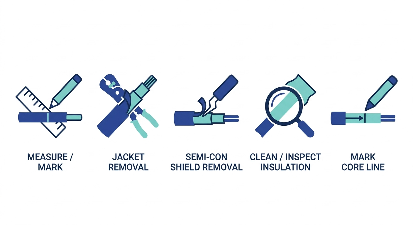
La préparation des câbles pour un kit de rétraction à froid suit un ordre bien défini — mesurer avant de couper, couper avant de nettoyer, nettoyer avant de marquer — car chaque étape dépend de l'état de la surface laissé par la précédente. Le fait de sauter des étapes, par exemple en marquant la ligne de retrait de l'âme avant que la surface de l'isolation ne soit entièrement nettoyée, est une source fréquente de défauts d'installation que les équipes de terrain ne découvrent qu'au moment des essais de mise en service.
Étape 1 — Mesurer et marquer la longueur des bandes
À l'aide du gabarit de dimensions fourni avec le kit ou d'un mètre ruban dont l'extrémité est alignée sur l'extrémité du câble, marquez successivement la longueur de retrait de la gaine, le point de découpe du blindage semi-conducteur et la longueur totale de mise à nu de l'isolation. Pour une terminaison type de classe 15 kV, la longueur d’exposition de l’isolation se situe généralement entre 150 mm et 250 mm, en fonction du kit utilisé et de la section du conducteur, le gabarit fourni par le fabricant prévalant sur les valeurs générales. Le fait de marquer ces trois points de référence avant de commencer toute découpe réduit le risque de constater, en cours d’opération, une découpe inégale ou trop courte.
Étape 2 — Retirer la gaine extérieure
La gaine extérieure est rainurée jusqu’à la ligne marquée à l’aide d’un outil de décapage rotatif ou à lame, réglé sur une faible profondeur — suffisamment profonde pour couper le matériau de la gaine, mais suffisamment faible pour éviter d’entailler le blindage semi-conducteur situé en dessous. La partie de la gaine est ensuite retirée, exposant ainsi le blindage sans le perturber davantage.
Étape 3 — Retirez le blindage semi-conducteur
Le blindage semi-conducteur est retiré jusqu'au point de découpe marqué à l'aide d'un outil de dénudage dédié plutôt que d'une lame à usage général, car un bord de découpe irrégulier concentre les contraintes électriques au point de transition. La tolérance de retrait de la gaine est généralement maintenue à quelques millimètres de la ligne marquée ; l’expérience sur le terrain montre qu’un bord de découpe irrégulier ou en gradins est une source récurrente de détections de décharges partielles lors des essais de mise en service ultérieurs, même lorsque le reste de la terminaison est correctement installé.
Étape 4 — Nettoyer et inspecter la surface de l'isolation
L'isolation mise à nu est essuyée à l'aide d'un solvant compatible avec l'isolation, en procédant de la découpe de la gaine vers l'extrémité du conducteur dans un seul sens, afin d'éviter de ramener des résidus semi-conducteurs sur la surface nettoyée. La surface est ensuite inspectée visuellement sous un éclairage adéquat afin de détecter la présence de particules de carbone incrustées, de rayures ou de rainures — toute imperfection visible à ce stade doit être corrigée avant de poursuivre, car elle ne pourra plus être corrigée une fois le manchon thermorétractable mis en place.
Étape 5 — Tracer la ligne de retrait du noyau
Le repère de référence final indique l'endroit où le technicien commencera à dérouler l'âme en plastique de la gaine thermorétractable à froid une fois que le kit sera positionné sur l'extrémité du câble préparée. Ce repère est établi en fonction de la longueur de mise à nu de l'isolation déterminée à l'étape 1 ; il n'est pas mesuré à nouveau séparément, afin de garantir la cohérence de toutes les dimensions par rapport au schéma d'origine.
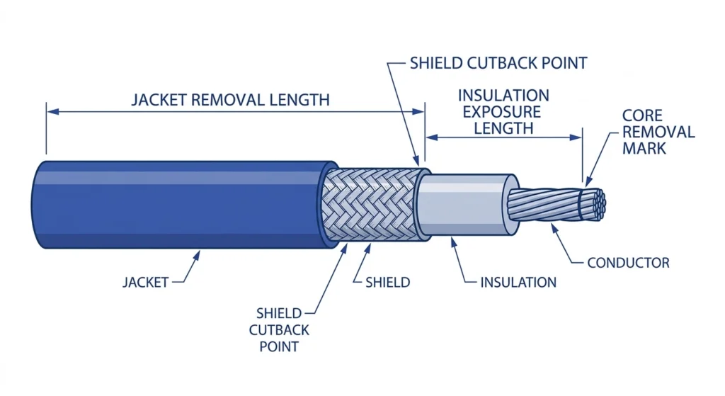
Coupe transversale d'une extrémité de câble moyenne tension correctement préparée, indiquant la longueur de gaine à retirer, le point de découpe du blindage semi-conducteur, la longueur d'isolation à mettre à nu et le repère de référence pour le retrait de l'âme.
Longueur des bandes et dimensions des découpes par classe de tension
La longueur de la bande et les dimensions de découpe ne sont pas universelles pour tous les kits de rétraction à froid : elles varient en fonction de la classe de tension, car la zone de contrôle des contraintes nécessite une exposition proportionnellement plus importante de l’isolation à mesure que la tension du système augmente. L'utilisation d'un gabarit prévu pour une classe de tension inférieure sur un câble de tension supérieure entraîne une distance de fuite insuffisante au point de découpe du blindage ; l'utilisation d'un gabarit surdimensionné entraîne un gaspillage d'isolant exposé et peut laisser un excès de câble dénudé à l'intérieur de la terminaison finie.
Plages dimensionnelles types par classe de tension
Le tableau ci-dessous présente les plages dimensionnelles générales observées pour les gammes courantes de kits de gaines thermorétractables pour moyenne tension. Le gabarit fourni par le fabricant du kit prévaut toujours sur les chiffres généraux, car les longueurs exactes des bandes varient en fonction de la section du conducteur et de la conception spécifique du kit, même au sein d'une même classe de tension.
Classe de tension
Longueur d'exposition de l'isolation
Tolérance de réduction du bouclier Semi-Con
Gamme typique de conducteurs
8,7/15 kV
150 mm–200 mm
±5 mm
25 mm² à 400 mm²
12/20 kV (20/24 kV)
180 mm – 230 mm
±5 mm
25 mm² à 630 mm²
26/35 kV
220 mm–280 mm
±5 mm à 8 mm
35 mm² à 800 mm²
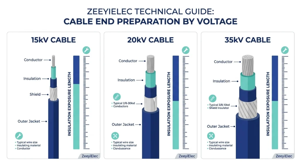
Comparaison côte à côte de la longueur d'exposition de l'isolation pour les différentes catégories de kits thermorétractables à froid (8,7/15 kV, 12/20 kV et 26/35 kV), illustrant la mise à l'échelle dimensionnelle proportionnelle.
Les exigences dimensionnelles de cette gamme sont globalement conformes au cadre d'essai des accessoires défini dans IEC 60502-4, qui définit les critères d'acceptation des essais de type pour les accessoires de câbles d'une tension nominale comprise entre 6 kV (Um = 7,2 kV) et 30 kV (Um = 36 kV) — bien que les tolérances exactes de réduction soient toujours confirmées par rapport aux instructions d'installation spécifiques au kit concerné plutôt qu'aux dispositions générales d'essai de la norme.
La section du conducteur influe également, dans la pratique, sur la tolérance au « cutback » : un conducteur de 630 mm² à 800 mm² de la classe 35 kV est doté d’un corps isolant plus lourd et plus rigide, qui tolère moins bien une découpe en biais du bord de « cutback », de sorte que les équipes de terrain travaillant dans cette plage supérieure consacrent généralement un peu plus de temps à chaque découpe qu’elles ne le font dans la classe de 15 kV.
Pour obtenir des conseils sur le choix de la classe de tension au-delà de la préparation dimensionnelle, consultez le site de ZeeyiElec Tableau complet de sélection des accessoires pour câbles, qui traite de la logique de sélection des composants sur toute la plage de tension.
Erreurs courantes lors de la préparation et comment les éviter
La plupart des défaillances lors de la préparation des gaines thermorétractables à froid sont dues à un petit nombre d'erreurs récurrentes plutôt qu'à une grande variété d'erreurs sans rapport les unes avec les autres. Identifier le schéma récurrent derrière chacune d'entre elles permet à l'équipe de les repérer avant la mise en place du kit, plutôt qu'après l'apparition d'un défaut plusieurs mois après la mise en service.
Résidus de semi-conducteurs présents sur l'isolant
Une fine couche de résidus semi-conducteurs, parfois invisible à l'œil nu, qui subsiste à la surface de l'isolant après le retrait du blindage, constitue l'une des causes principales les plus courantes de défaillance prématurée par effet de piste au niveau de l'interface du cône de contrainte. Ce phénomène se produit le plus souvent lorsqu'on utilise une lame à usage général à la place d'un outil dédié au retrait du blindage, ou lorsque le mouvement de nettoyage ramène les résidus sur une section déjà nettoyée. La solution est d’ordre procédural : utilisez l’outil approprié pour retirer la gaine de protection, nettoyez dans un seul sens et inspectez la surface sous un éclairage puissant — un léger reflet ou une décoloration qui capte la lumière oblique est souvent le seul signe visible de la présence de résidus avant que ceux-ci ne deviennent un problème en service.
Coupes irrégulières ou en biais
Une découpe de la gaine ou du blindage qui n’est pas perpendiculaire à l’axe du câble crée un point de transition irrégulier, ce qui concentre localement les contraintes électriques du côté où la découpe est la plus courte. Cela résulte généralement d’une exécution précipitée de l’incision initiale ou de l’utilisation d’un outil de dénudage mal positionné sur le câble. L'expérience sur le terrain montre que cette erreur est plus fréquente avec des conducteurs de grande section (supérieure à environ 400 mm²), où l'outil doit parcourir une plus grande circonférence et où il est plus facile de provoquer un décalage ; ralentir la coupe et faire pivoter le câble plutôt que l'outil, lorsque la configuration le permet, permet d'obtenir un résultat plus droit.
Contamination due à la manipulation ou à l'environnement
Le contact des mains nues, de la poussière en suspension dans l'air ou de l'humidité ambiante avec la surface isolante nettoyée, entre le nettoyage et la pose du kit, réintroduit précisément la contamination que l'étape de nettoyage était censée éliminer. Ce risque s'accroît lors des installations en extérieur ou dans des chambres souterraines, où la surface d'isolation exposée reste à l'air libre pendant des périodes plus longues au cours des différentes étapes de préparation. Les équipes gèrent généralement ce risque en réduisant au minimum le délai entre le nettoyage final et l'installation du kit, et en recouvrant temporairement la section préparée d'une protection propre lors de toute pause inévitable.
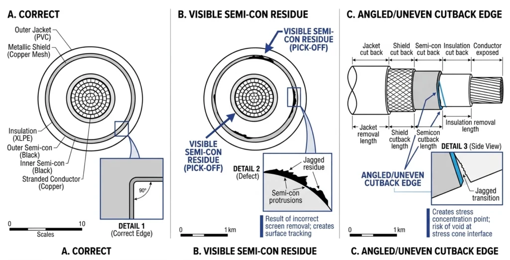
Trois coupes transversales d'extrémités de câbles préparées, comparant une terminaison correctement nettoyée et coupée à des défauts courants : des résidus semi-conducteurs et un bord de découpe en biais.
[Regard d'expert]
Un léger reflet sous une lumière oblique est souvent le seul signe visible de résidus de semi-conducteurs
Les coupes en biais sont plus visibles sur les conducteurs de plus de 400 mm² : ralentissez et faites pivoter le câble, et non l'outil.
Ne laissez jamais une surface nettoyée à l'air libre plus longtemps que nécessaire avant d'appliquer le kit.
Vérification des préparatifs avant l'installation du kit
Avant de dérouler l’âme du kit thermorétractable à froid, une dernière vérification permet de s’assurer que toutes les étapes précédentes respectent les tolérances — c’est le dernier moment où une correction est encore facile à effectuer, car corriger un problème de dimensions ou de propreté une fois le kit installé sur le câble implique généralement de le jeter et de tout recommencer. Cette vérification ne prend que quelques minutes, mais permet de détecter la plupart des erreurs de préparation avant qu’elles ne se répercutent sur la terminaison ou la jonction finale.
Le contrôle porte sur trois points successifs : vérifier que la longueur d’isolation dénudée et le point de découpe du blindage correspondent toujours aux dimensions indiquées (généralement dans une fourchette de ±5 mm à 8 mm par rapport à la tolérance spécifiée dans le kit, en fonction de la classe de tension), vérifier que la surface de l’isolation ne présente aucun résidu visible, aucune rayure ni aucune contamination sous un éclairage adéquat, et vérifier que la classe de tension et la gamme de conducteurs du kit correspondent toujours au câble à raccorder avant de retirer l’âme. Tout écart constaté à ce stade est corrigé immédiatement plutôt que d’être reporté lors de l’installation.
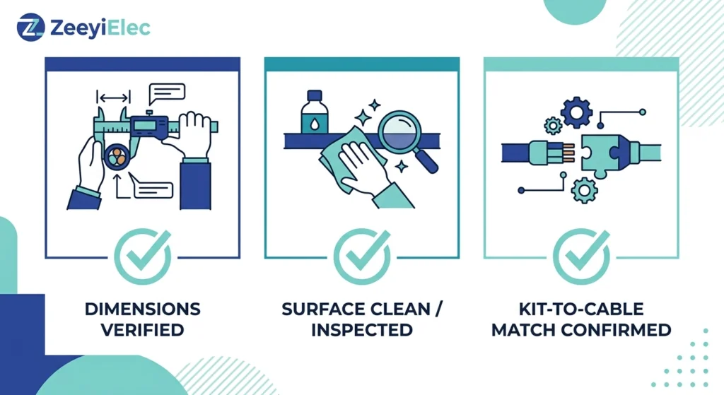
Liste de contrôle en trois points à effectuer avant l'installation, portant sur la précision dimensionnelle, la propreté de la surface d'isolation et la compatibilité entre la classe de tension du kit et celle du câble.La qualité de la préparation effectuée à ce stade est déterminante pour la suite de l'installation. Pour obtenir des données dimensionnelles spécifiques à un projet, choisir un kit ou bénéficier d’une assistance technique permettant de déterminer le kit de gainage à froid adapté à une classe de tension et à une section de conducteur données, l’équipe d’ingénieurs de ZeeyiElec peut examiner directement les spécifications des câbles et les conditions sur site. Contactez-nous à l’adresse [email protected] pour bénéficier d’une consultation technique ou d’une assistance pour vos demandes de devis concernant l’ensemble de la gamme ZeeyiElec. accessoires pour câbles gamme, comprenant notamment des kits de raccordement à rétraction à froid et des kits de jonction adaptés à la classe de tension de votre projet.
Questions fréquemment posées
Combien de temps dure généralement la préparation d'un câble thermorétractable à froid ?
La mise en service d'une dérivation monophasée à moyenne tension prend généralement entre 20 et 40 minutes à une équipe qualifiée ; toutefois, cette durée peut être prolongée en cas de conducteurs de section supérieure à 400 mm² ou d'accès restreint à la chambre technique. De plus, les installateurs qui utilisent pour la première fois une nouvelle gamme de kits doivent prévoir du temps supplémentaire pour la vérification initiale des dimensions.
La préparation à la pose par rétraction à froid peut-elle être effectuée dans des conditions de chantier humides ou pluvieuses ?
La pose de gaines thermorétractables à froid est plus tolérante à l'humidité ambiante que celle des gaines thermorétractables à chaud, puisqu'elle ne nécessite ni flamme nue ni source de chaleur ; toutefois, la surface à isoler doit tout de même être sèche et exempte de condensation juste avant la pose du kit. La présence d'eau stagnante ou de pluie sur le chantier nécessite généralement la mise en place d'un abri temporaire ou le report des travaux.
Que se passe-t-il si le blindage semi-conducteur n'est pas entièrement retiré ?
Les résidus semi-conducteurs présents au niveau du point de découpe du blindage créent un chemin conducteur localisé qui concentre les contraintes électriques ; il s'agit là d'une cause fréquente de défaillance par effet de piste au fil du temps. Par conséquent, tout résidu visible ou suspect doit être éliminé et faire l'objet d'une nouvelle inspection avant l'installation du kit, plutôt que d'attendre que les essais de mise en service le détectent.
Les étapes de préparation à la pose par rétraction à froid diffèrent-elles selon qu'il s'agit de kits de raccordement ou de kits de jonction ?
La séquence de base comprenant la mesure, le dénudage, le nettoyage et le marquage est similaire dans les deux cas, mais les kits de raccordement nécessitent généralement une préparation des deux extrémités du câble ainsi qu'un alignement entre celles-ci, ce qui implique une préparation supplémentaire des connecteurs de conducteurs et une vérification de la symétrie, étapes qui ne sont pas nécessaires avec les kits de terminaison.
Quels sont les outils indispensables et ceux qui sont facultatifs pour la préparation du rétrécissement à froid ?
Un outil de dénudage de gaine, un outil spécifique pour retirer le blindage semi-conducteur, un mètre ruban ou un gabarit fourni avec le kit, ainsi qu’un solvant de nettoyage compatible avec l’isolation sont indispensables pour chaque intervention, tandis que les outils d’ébavurage, les balances non métalliques et les lubrifiants spécifiques au kit sont utiles mais ne sont requis que lorsque les instructions du fabricant le précisent.
Comment vérifiez-vous que les longueurs des bandes sont correctes avant de continuer ?
Juste avant le retrait de l'âme, vérifiez à nouveau la longueur de retrait de la gaine, le point de découpe du blindage et la longueur d'exposition de l'isolation par rapport au gabarit dimensionnel fourni avec le kit, en vous assurant que chacun de ces éléments respecte la tolérance indiquée par le fabricant, qui est généralement de quelques millimètres pour les classes de tension MT.
Les erreurs commises lors de la préparation de la gaine thermorétractable peuvent-elles être corrigées une fois le noyau retiré ?
Certains problèmes mineurs, comme une légère contamination de surface, peuvent parfois être résolus par un nettoyage supplémentaire s’ils sont détectés immédiatement ; en revanche, les erreurs dimensionnelles, telles qu’une découpe incorrecte du blindage, ne peuvent généralement pas être corrigées une fois que le noyau a été retiré et que le kit est en train de se contracter sur le câble, ce qui fait de la vérification préalable à l’installation l’étape de contrôle la plus fiable.
yoyo shi
Yoyo Shi écrit pour ZeeyiElec, en se concentrant sur les accessoires de moyenne tension, les composants de transformateurs et les solutions d'accessoires de câbles. Ses articles couvrent les applications des produits, les bases techniques et les perspectives d'approvisionnement pour les acheteurs de l'industrie électrique mondiale.





 English
 한국어
한국어 العربية
 Español
 हिन्दी
 தமிழ்
தமிழ் Deutsch (Sie)
 Français
 Português do Brasil
 Русский