Field crews terminate medium-voltage cables under time pressure, often without access to a heat source or a controlled indoor environment. A cold shrink cable termination installation solves exactly this constraint: the insulation stress control components arrive pre-expanded on a removable plastic core, and the installer shrinks them into place mechanically rather than with a torch or heat gun. Having walked crews through this process on live 15kV and 35kV distribution transformers, the steps below reflect how the installation is actually sequenced in the field — not just the manufacturer’s data sheet instructions.
Watch the full installation on a 35kV transformer bushing below:
What Is a Cold Shrink Cable Termination?
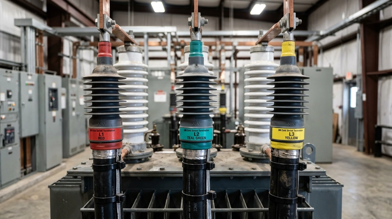
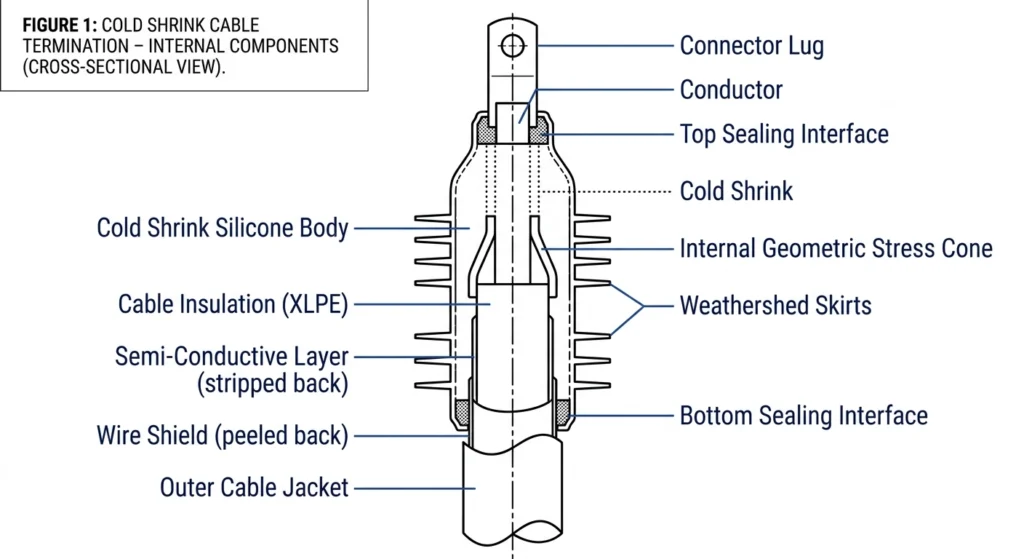
A cold shrink cable termination is a stress-control and insulation component made from pre-stretched EPDM or silicone rubber, held in an expanded state by a spiral-wound plastic core. During installation, the technician positions the expanded unit over the prepared cable end and pulls the core tab, allowing the rubber to recover (shrink) onto the cable at ambient temperature. This distinguishes it from heat shrink terminations, which require a controlled heat source to recover a similar rubber or polymer sleeve. Cold shrink construction typically integrates a stress cone, a weathershed skirt system, and a sealing interface in a single molded unit, which reduces the number of discrete parts an installer has to manage on site.
Before starting, confirm the kit matches the cable’s conductor size range and the system voltage class — cold shrink kits are sized to a specific outer-diameter window, and forcing an undersized or oversized unit onto the cable compromises the stress control geometry.
Cold shrink termination kit rated for the correct voltage class and cable size range
Cable stripping and semi-conductive shaving tools
Solvent-based cleaning wipes (manufacturer-specified, non-petroleum where required)
Abrasive cloth for grounding braid and shield preparation
Torque wrench for lug connections
Insulation resistance tester for post-installation verification
Cold Shrink Cable Termination Installation: Step-by-Step Process
Step 1: Prepare the Cable and Work Area
De-energize and ground the circuit per site lockout/tagout procedure before any cable preparation begins. Clean the work area to limit contamination — cold shrink components are sensitive to dust, moisture, and oil residue on the cable surface, since any of these can create a leakage path along the interface once the termination is in service.
Step 2: Strip and Prepare the Cable End
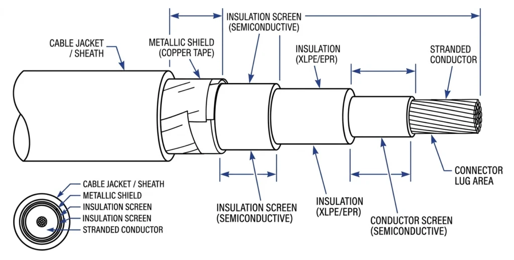
Remove the outer jacket, shield, and insulation to the dimensions specified in the kit instructions, which vary by manufacturer and cable construction. Bevel the insulation edge and remove semi-conductive residue from the insulation surface completely — any semi-conductive material left behind under the stress cone is a common source of partial discharge and premature failure. Clean the exposed insulation with the specified solvent wipe before proceeding.
Cable end showing stripped jacket, shield, and insulation zones with dimension callouts
Step 3: Position the Cold Shrink Termination
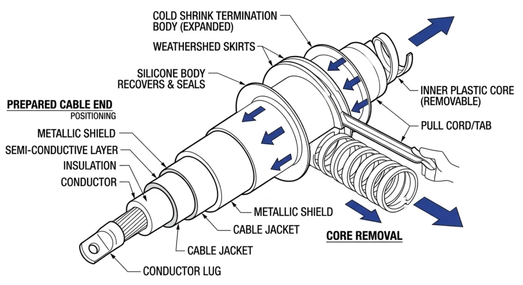
Slide the pre-expanded termination assembly (still on its core) over the cable end, aligning the stress cone with the point where the shield was cut back. Positioning accuracy at this step matters more than it might appear — once the core is pulled and the rubber recovers, the unit cannot be repositioned.
Step 4: Remove the Core and Allow the Termination to Shrink
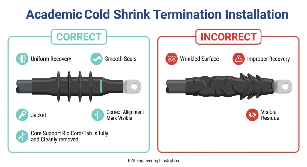
Locate the core tab and pull it steadily, rotating the core counterclockwise as it unwinds. The rubber body will recover onto the cable within seconds, with no external heat input required. Work from one end to the other in a single continuous motion rather than pulling in short bursts, which can leave uneven recovery along the body.
Termination sliding onto cable end, core tab being pulled, directional arrows showing shrink direction
Step 5: Inspect and Test the Completed Termination
Visually confirm full, even recovery with no wrinkles, trapped air, or visible gaps at the stress cone interface. Complete the lug connection and torque to the manufacturer’s specification, then perform an insulation resistance test before re-energizing, referencing the IEEE 400 series field testing guides for applicable VLF or IR test methods. [VERIFY STANDARD: confirm applicable field acceptance test method and minimum IR value against the project specification.]
Common Installation Mistakes to Avoid
Mistake
Consequence
Incomplete semi-conductive shaving
Partial discharge at stress cone interface
Wrong kit size for cable OD range
Poor interference fit, reduced sealing pressure
Contaminated cable surface before shrink
Tracking and premature insulation breakdown
Pulling core unevenly or in stages
Wrinkled recovery, inconsistent stress control
Skipping post-install IR test
Undetected installation defect energized into service
On crews we’ve observed in the field, the two mistakes above the fold — incomplete semi-conductive shaving and skipping the post-install test — account for the majority of avoidable rework, since both are invisible at the time of installation and only surface as a failure weeks or months later.
Correct vs. incorrect installation (e.g. clean stress cone interface vs. residual semi-conductive shaving, wrinkled recovery)
Cold Shrink vs Heat Shrink: When Installation Method Matters
Cold shrink and heat shrink terminations solve the same insulation and stress-control problem through different mechanisms, and the choice affects site logistics as much as electrical performance. Cold shrink removes the need for an open flame or heat gun, which makes it the more practical choice for indoor switchgear, confined vaults, or any site where hot work permits are difficult to obtain. A full comparison of the two technologies — including voltage class suitability and installation time — is covered in Cold Shrink vs Heat Shrink: Engineering Selection Framework.
Voltage Class and Compatibility Reference
Voltage Class
Common Cold Shrink Application
1kV (LV)
Distribution service terminations
10kV (MV)
Indoor switchgear, pad-mount transformers
15kV (MV)
Substation and feeder terminations
35kV (MV)
Transformer bushing terminations, outdoor riser poles
If the project also involves bushings, tap changers, or fuse assemblies on the transformer side of the connection, the Transformer Accessories category and the Complete Selection Map for Cable Accessories provide a broader selection framework for matching accessories to the project’s voltage class and environment.
Frequently Asked Questions
Does a cold shrink termination require any heat source during installation?
No. The rubber body is pre-expanded at the factory and held on a removable core. Recovery happens at ambient temperature once the core is pulled — no torch, heat gun, or other heat source is needed.
Can cold shrink terminations be used at 35kV?
Yes, cold shrink terminations are manufactured across LV and MV voltage classes, including 35kV, provided the kit is selected to match the project’s voltage class and cable conductor size range.
What causes a cold shrink termination to fail prematurely?
The most common field causes are incomplete removal of semi-conductive shield residue at the stress cone, contamination on the cable surface before shrink, and using a kit sized outside the cable’s compatible OD range.
How long does a cold shrink termination take to install compared to heat shrink?
Cold shrink installation is generally faster because there is no heat-source setup or controlled recovery time; the rubber recovers within seconds of the core being removed, whereas heat shrink requires methodical heat application across the full body.
yoyo shi
Yoyo Shi writes for ZeeyiElec, focusing on medium-voltage accessories, transformer components, and cable accessory solutions. Her articles cover product applications, technical basics, and sourcing insights for global electrical industry buyers.





 English
 한국어
한국어 العربية
 Español
 हिन्दी
 தமிழ்
தமிழ் Deutsch (Sie)
 Français
 Português do Brasil
 Русский