This LV bushing inspection checklist for factory acceptance walks through the buyer-witnessed or supplier-executed verification steps performed on finished production units before they leave the factory — confirming that the specific batch shipping against a purchase order actually matches the ordered rating, not just the general product family. FAT typically layers on top of routine testing, adding buyer-specific checks: nameplate-to-PO conformance, visual and dimensional inspection against the approved drawing, and a subset of electrical verification tests witnessed or reviewed by the buyer or a third-party inspector before release for shipment. The same FAT discipline applies across transformer accessories and cable accessories product lines, though the specific checkpoints differ by component type.
For LV bushings specifically, FAT scope is shaped by the component’s operating profile — continuous current ratings commonly spanning 600 A to 5000 A and a voltage class of 1.2 kV to 3.0 kV — because the checks that matter most at this stage are the ones that predict long-term terminal performance, not just initial dielectric integrity. A bushing can pass a one-time dielectric test and still fail in service eighteen months later from a joint that was never checked for proper seating during FAT.
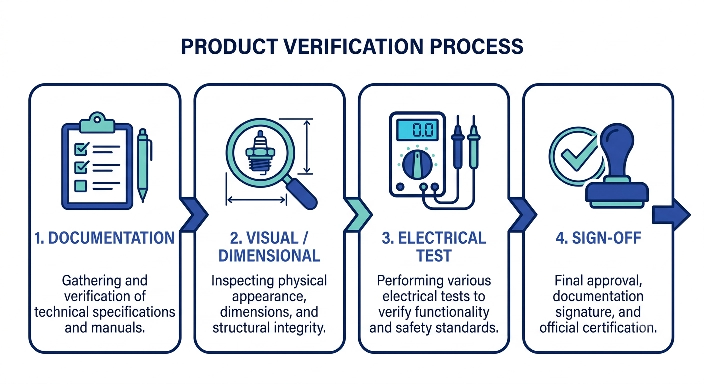
FAT is typically scheduled after production completion and before packing, giving the buyer or inspector a final opportunity to reject or request rework before goods are containerized. Projects that skip a structured FAT checklist and rely only on the supplier’s routine test report tend to see a higher rate of post-shipment disputes — not because the product was defective, but because a dimensional or documentation mismatch surfaces only at the installation site, when correction is far more expensive. The sections below work through FAT in the order it’s typically executed: documentation first, then visual and dimensional inspection, then electrical verification, then disposition.
Pre-FAT Documentation and Nameplate Verification
Before any physical inspection begins, FAT starts with a paper check: confirming that the documentation package accompanying the batch matches what was actually ordered. This step catches a surprising share of mismatches early — a supplier substituting an equivalent-but-different insulation material, or a batch produced against a superseded drawing revision, rarely shows up in a visual scan but always shows up on the paperwork.
Nameplate Data Cross-Check
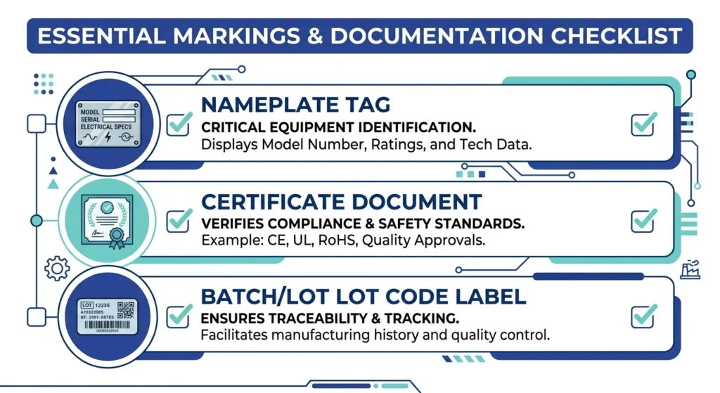
Each bushing’s nameplate should be checked line-by-line against the purchase order and approved drawing, not just glanced at for the general product name. Key fields to verify include rated voltage class (commonly 1.2 kV or 3.0 kV for LV bushings), continuous current rating, insulation material designation (HTN, porous resin, or porcelain), terminal configuration, and manufacture batch or lot code for traceability. A mismatch between nameplate current rating and the PO — for example, a unit stamped 2500 A shipped against an order specifying 4000 A — is a hard rejection, not a note for follow-up, since substitution at this level indicates either a picking error or an unauthorized design change.
The same discipline carries over from MV practice: nameplate reading conventions for MV bushings follow a similar logic of cross-referencing voltage class, BIL, and batch data against procurement records, even though LV bushings carry a simpler rating set.
Test Certificate and Traceability Review
Every batch should arrive with routine test certificates covering, at minimum, dielectric withstand and contact resistance results for the specific lot — not a generic type-test certificate reused across shipments. A routine test certificate with a batch number that doesn’t match the physical units in the crate is one of the more common paperwork failures caught at FAT, and it should trigger a hold until the supplier resolves the discrepancy rather than being waved through on the assumption of clerical error. Material traceability records — confirming which resin or HTN lot went into a given production run — matter most when a field failure investigation later needs to isolate whether a defect is batch-specific or systemic.
Documentation checklist showing nameplate fields, routine test certificate scope, and batch traceability data required before physical FAT inspection.
[Expert Insight]
A nameplate current rating alone doesn’t confirm terminal configuration — cross-check both fields independently
Batch/lot codes on the certificate should be traceable to physical marking on the unit, not just the packing list
Superseded drawing revisions are the single most common source of “clean electrical, failed dimensional” rejections
Visual and Dimensional Inspection Checklist
Once documentation clears, physical inspection moves to the units themselves. Visual and dimensional checks catch defects that electrical testing alone won’t reveal — a hairline crack in a resin housing or an out-of-tolerance flange won’t necessarily fail a dielectric test on day one, but it predicts a field failure well before the bushing’s expected service life.
Bushing Body and Insulation Surface
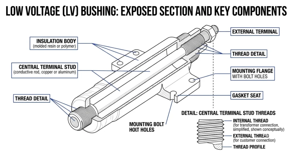
Inspect the full insulation body under adequate lighting for surface defects: cracks, voids, chalking, or incomplete resin cure on epoxy/porous resin units, and chips or crazing on porcelain. Surface contamination from mold release agents or handling residue should be noted, since it can mask a hairline defect during a quick visual pass. Units with minor surface porosity that pass a cursory glance at FAT have, in field experience, gone on to develop tracking paths within 2–3 years of outdoor service — a reminder that this step deserves closer attention than it typically gets on a tight inspection schedule.
Terminal Stud and Threading
Check terminal stud thread condition (no galling, cross-threading, or deformation), thread engagement length against the drawing, and plating condition — tin or silver plating should be continuous with no exposed base metal at the contact area. A damaged thread that looks acceptable on visual inspection can still fail to achieve proper clamping torque during field installation, which is the single largest driver of long-term terminal overheating.
Mounting Flange and Gasket Seat
Verify flange dimensions against the approved drawing — bolt circle diameter, hole pattern, and flatness — since even a small deviation can prevent proper gasket compression at the tank wall interface. Inspect the gasket seating surface for scratches or tool marks that could create a leak path once installed.
Flatness tolerance on the mounting flange is typically held within ±0.3 mm across the sealing face; deviations beyond this can compromise gasket compression even when bolt torque is applied correctly.
Cross-sectional line-art diagram of an LV bushing identifying the insulation body, terminal stud threading, and mounting flange inspection zones.
Electrical Test Verification at FAT
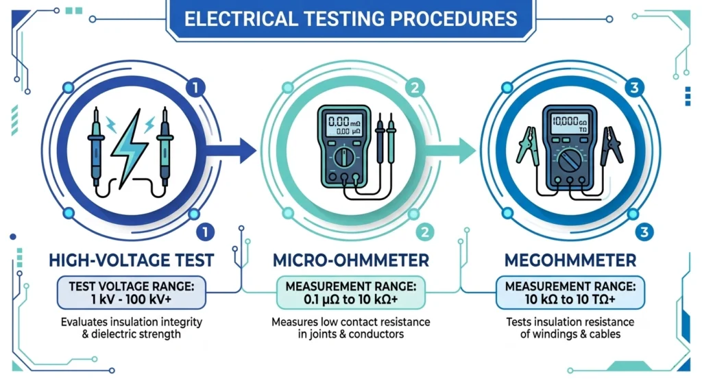
Electrical testing at FAT confirms the bushing performs to its rated parameters, not just that it looks correct. For LV bushings, this stage is typically a reduced version of full routine testing, built around three checks.
Dielectric Withstand Test
The dielectric withstand test applies an AC voltage above the bushing’s rated voltage for a defined duration to confirm the insulation system has no latent weakness. For LV bushings rated 1.2 kV, a typical withstand test level falls in the range of 10 kV AC for 1 minute; units rated 3.0 kV commonly see proportionally higher test levels. [VERIFY STANDARD: exact AC withstand voltage/duration for LV secondary bushings per ANSI/IEEE C57.12.00 dielectric insulation level table — confirm against ZeeyiElec’s internal test spec, as public sources do not list this parameter for LV bushings specifically]. A unit that flashes over or shows sustained leakage current below the expected threshold fails outright — there’s no partial pass at this stage.
Contact Resistance Measurement
Contact resistance is measured across the terminal-to-conductor joint using a micro-ohmmeter, since even a well-torqued joint with surface contamination can show elevated resistance that predicts future overheating. Acceptable values depend on current rating and terminal geometry, but resistance readings that exceed roughly 20–30% above the baseline established during type testing warrant rework before the unit ships. Contact resistance is arguably the single most predictive FAT measurement for terminal reliability — more so than the dielectric test — because it directly reflects joint quality rather than bulk insulation condition.
Insulation Resistance Check
Insulation resistance (IR) is measured with a megohmmeter, typically at 500 V or 1000 V DC depending on the bushing’s rated voltage class, with acceptable readings generally expected above 1000 MΩ for a unit in good condition. A reading that falls significantly below this threshold — particularly if it drops further under sustained applied voltage — points to moisture ingress or a contamination path rather than a bulk material defect.
These three tests together give a buyer reasonable confidence that a batch matches its type-test baseline without repeating the full qualification program, consistent with how transformer accessories are selected against multiple interacting parameters rather than a single pass/fail figure.
Sequential infographic of the three FAT electrical tests — dielectric withstand, contact resistance, and insulation resistance — with typical acceptable value ranges.
Common Rejection Triggers and Field Case Notes
Most FAT rejections trace back to a small number of recurring issues rather than random defects, and recognizing the pattern speeds up disposition decisions on the inspection floor.
Case One: Torque-Related Rejection Disguised as an Electrical Fail
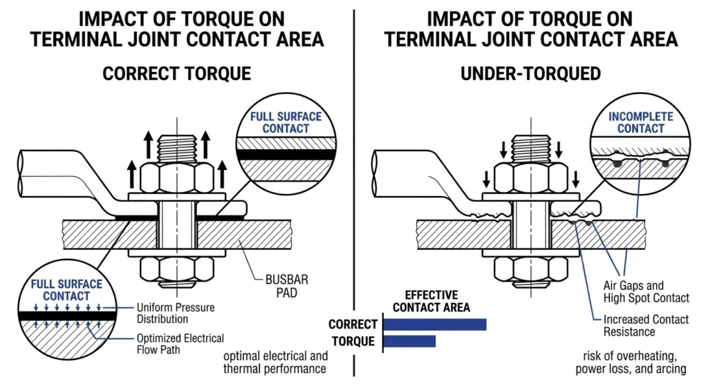
On one FAT inspection, a batch of LV bushings rated for 4000 A showed contact resistance readings roughly 35% above the type-test baseline — enough to trigger a hold. The initial assumption was a plating defect, but disassembly showed the terminal studs had been hand-tightened during production assembly rather than torqued to spec, leaving inconsistent clamping force across the batch. Re-torquing the affected units to the correct value brought resistance readings back within range on retest. The lesson: an elevated contact resistance reading at FAT should prompt a torque verification before assuming a material or plating problem.
Case Two: Dimensional Mismatch from a Drawing Revision Gap
A separate batch was rejected at FAT when the mounting flange bolt pattern didn’t match the current approved drawing — the supplier had produced against a prior drawing revision that hadn’t been formally superseded in their internal system. The units passed every electrical test cleanly; the defect was purely dimensional and would only have surfaced during field installation, likely after the units had already been shipped to a project site. This is a common failure mode when a design change occurs mid-production run without a hard cutover point, and it reinforces why dimensional inspection against the current drawing revision — not just the general part number — belongs in every FAT pass, not just the electrical checks.
Both cases point to the same principle: FAT is most useful when inspectors treat a passing electrical result and a passing visual result as independent checks, not a single combined pass/fail. A unit can fail on one axis while looking clean on the other, and catching that gap before shipment is the entire purpose of running a structured checklist rather than a spot check.
Side-by-side line-art comparison of a correctly torqued terminal joint versus an under-torqued joint, illustrating reduced contact area.
[Expert Insight]
Elevated contact resistance at FAT: check torque before suspecting plating or material defects
Clean electrical results don’t clear a batch — verify dimensional data against the current drawing revision, not the part number alone
Treat visual/dimensional and electrical results as two independent pass/fail axes, not one combined score
Sign-Off, Sampling Plan, and Nonconformance Handling
FAT concludes with a structured disposition step: how many units get inspected, what happens when a unit fails, and who signs off before release for shipment.
AQL Sampling Basis
Rather than inspecting 100% of a production batch — rarely practical for orders running into the hundreds of units — FAT commonly applies an Acceptable Quality Level (AQL) sampling plan based on the ANSI/ASQ Z1.4 general inspection framework, with AQL 1.0 or 1.5 for major defects being typical on transformer accessory orders. Under a typical AQL 1.5 plan, a batch of 500 units might require a sample of around 50 units for inspection, with acceptance contingent on finding no more than 2 major defects in that sample; exact sample sizes and acceptance numbers should be confirmed against the buyer’s specified sampling table, since these can vary by contract. Electrical tests (dielectric withstand, IR) are more commonly run at a higher sampling rate or 100%, since these are lower-cost, non-destructive checks that catch batch-wide process issues efficiently.
Nonconformance Disposition Steps
When a sample unit fails inspection, three outcomes are available: full batch rejection, tightened re-inspection (doubling the sample size to confirm whether the defect is isolated or systemic), or supplier rework with a documented corrective action before resubmission. The choice depends on defect severity and whether the root cause traces to an isolated assembly error — like the torque issue in the earlier case — versus a process-level problem affecting the full batch. A rework-and-resubmit path is generally acceptable for dimensional or torque-related findings; a dielectric failure on more than one sample unit typically warrants full-batch rejection rather than selective rework, since it suggests a material or process defect that individual correction won’t reliably fix.
Final sign-off should be documented with inspector name, sample size and result, any nonconformances and their disposition, and reference to the specific PO and drawing revision — this record becomes the traceability anchor if a field issue surfaces later and the batch needs to be re-examined against its original FAT result.
Get FAT-Ready LV Bushings from ZeeyiElec
This LV bushing inspection checklist works best when applied to a supplier whose production process already tracks toward those checkpoints. A structured FAT checklist works best when applied to a supplier whose production process already tracks toward those checkpoints — consistent torque control on terminal assembly, drawing revision control tied to purchase orders, and routine test data retained at the batch level for traceability. ZeeyiElec manufactures LV bushings across the 1.2 kV–3.0 kV voltage range and 600 A–5000A+ current ratings, with HTN, porous resin, and porcelain insulation options selected to match thermal and environmental requirements at the specification stage rather than after a field failure forces a redesign.
For buyers preparing an RFQ or a FAT witness schedule, the transformer accessories RFQ checklist covers the parameter set needed to get an accurate quotation and avoid the kind of drawing-revision or nameplate mismatches described earlier in this guide — the same gaps that most often surface as FAT rejections.
Share your voltage class, current rating, terminal configuration, and target FAT date, and ZeeyiElec’s engineering team can confirm production scheduling and inspection availability.
A standard FAT for a single batch usually takes half a day to a full day, depending on batch size and whether electrical tests are run at 100% or on a reduced sample; larger orders spanning multiple current ratings or terminal configurations can extend this to two days.
What is the acceptable sample size for LV bushing FAT?
Sample size is generally set by an AQL sampling table based on batch quantity and defect severity class, with a batch of a few hundred units commonly requiring a sample in the range of 10–15% for visual/dimensional checks, though buyers sometimes specify a higher fixed percentage for critical projects.
Can FAT be waived for repeat orders from the same supplier?
Some buyers reduce FAT scope for repeat orders with a proven supplier track record, but skipping FAT entirely is generally not advisable even for repeat business, since production changes such as a material substitution or drawing revision can occur between orders without formal notice.
What causes most LV bushing rejections at FAT?
Elevated contact resistance from inconsistent terminal torque and dimensional mismatches from unsynchronized drawing revisions account for a large share of FAT rejections, more so than outright dielectric failures, which tend to be rarer and usually point to a material or process-level issue.
Is a witness FAT the same as third-party inspection?
No — a witness FAT involves the buyer or their representative observing the supplier’s own test process, while third-party inspection uses an independent inspection agency to perform or verify testing, and the two are sometimes combined on higher-value or first-order shipments.
What documentation should accompany LV bushings after FAT sign-off?
A complete package typically includes the routine test certificate for the specific batch, the FAT inspection report with sample results and any nonconformance disposition, and the nameplate/drawing revision reference used for the inspection, all traceable to the batch or lot code marked on the units.
yoyo shi
Yoyo Shi writes for ZeeyiElec, focusing on medium-voltage accessories, transformer components, and cable accessory solutions. Her articles cover product applications, technical basics, and sourcing insights for global electrical industry buyers.





 English
 한국어
한국어 العربية
 Español
 हिन्दी
 தமிழ்
தமிழ் Deutsch (Sie)
 Français
 Português do Brasil
 Русский