Pre-Installation Verification and Accessory Staging
Before unwrapping a single tube or applying any heat, field personnel must verify that the accessory kit matches the physical and electrical parameters of the cable in the trench or switchgear. A successful installation begins with strict quality control during the staging phase, preventing specification mismatches that account for a significant percentage of early field failures.
Verifying Cable and Accessory Compatibility
Heat shrink materials operate on a defined shrinkage ratio (typically 3:1 or 4:1). Consequently, an incorrectly sized kit will either fail to clear the cable during staging or fail to exert sufficient radial pressure once shrunk. Cross-reference the kit label against the cable’s specific voltage class (e.g., 10kV, 20(24)kV, or 35kV). Conductor cross-section must also align perfectly; a termination kit rated for 95–240 mm² cannot reliably seal a 400 mm² conductor, and attempting to force it risks splitting the tubing during the heating phase.
Ensure the insulation diameter over the primary dielectric falls strictly within the kit’s specified application range (e.g., 23.5 mm ≤ D ≤ 34.0 mm). This tolerance guarantees that the stress control tube maintains intimate, void-free contact with the cable insulation.
Environmental Readiness and Tooling Check
The field environment directly impacts the integrity of heat shrink installations. Unlike cold shrink technologies that rely on pre-expanded elastomers, heat shrink requires active thermal application, making it highly sensitive to ambient weather conditions. Verify that the ambient temperature is suitable; if working below 5°C, the cable jacket and insulation must be gently pre-heated to prevent the hot mastic from instantly chilling upon contact, which causes poor bonding and moisture ingress pathways. Ensure relative humidity is below 80 percent to prevent moisture entrapment under the tubing.
Next, verify the field tooling. A standard, aggressive blowtorch is insufficient and dangerous for polymeric insulation. Installers must use a soft, bushy flame—often a yellow-tipped flame—rather than a sharp, blue cutting flame to prevent scorching or blistering the heat shrink materials. Verify the torch nozzle size is appropriate for the cable diameter; a 50 mm nozzle is standard for most medium-voltage jointing tasks. Finally, ensure a clean, dry staging area is established to keep all accessory components free of dirt, metallic dust, or trench mud before they are positioned on the cable.
Expert Staging Insights
Staging Verification: Always slide outer protection tubes onto the cable prior to crimping the connector, as forgetting outer sleeves causes over 15 percent of jointing delays.
Solvent Selection: Never use standard industrial degreasers for cleaning cable components; strictly utilize approved, non-linting, highly volatile solvent wipes (e.g., Isopropyl Alcohol >90 percent) that leave zero residue.
Inventory Control: Count all mastic tapes and stress control components against the kit bill of materials before starting, because missing a single layer compromises the entire dielectric boundary.
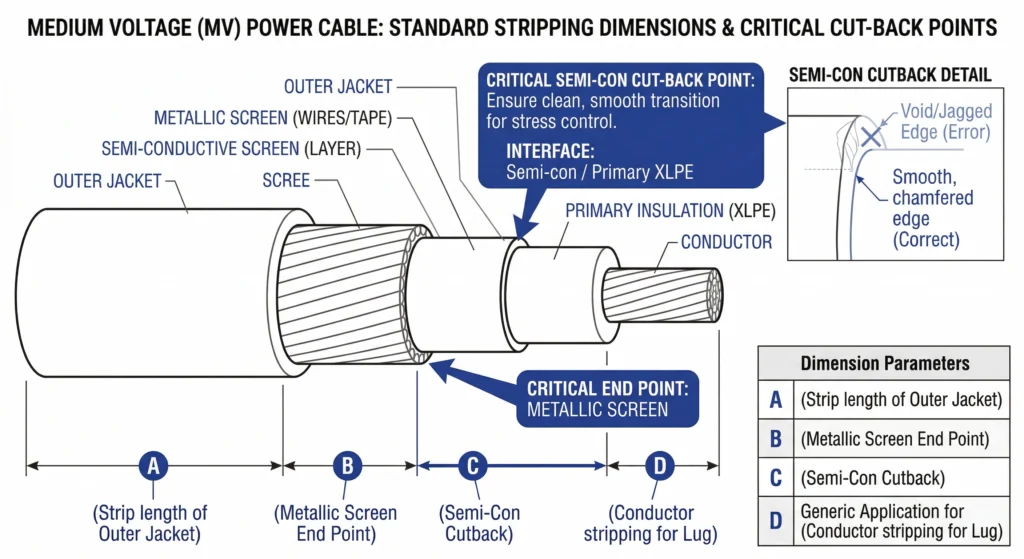
Cable Preparation and Dimension Control
The foundation of any reliable Heat Shrink Cable Accessories installation lies in precise cable preparation. Field data consistently shows that poor stripping execution is responsible for more premature failures than defective accessory components. Installers must adhere strictly to the dimension sheet provided in the specific kit.
FIG-01:Precise dimensional control during cable preparation ensures the stress control tube properly overlaps the semi-con screen cutback.
Outer Jacket Removal and Armor Grounding
The first critical step involves removing the outer cable jacket to expose the metallic armor or copper wire shield. The strip-back length typically ranges from 300 mm to 450 mm for medium-voltage terminations, depending on whether it is an indoor or outdoor configuration. Once exposed, the metallic screen must be thoroughly cleaned with approved, non-linting solvent wipes to ensure a low-resistance path for the grounding braid.
When securing the tinned copper grounding braid, installers must use a constant force spring rather than standard hose clamps or localized binding wire. A correctly sized constant force spring provides continuous 360-degree radial pressure. This dynamic pressure adapts to the cable’s thermal expansion and contraction cycles under heavy load, preventing a loose ground connection that could trigger tracking over the cable jacket.
Semiconductor Screen Scoring and Removal
Removing the extruded semiconductive (semi-con) layer is the most high-risk operation in the entire preparation phase. Installers must score the semi-con layer using a calibrated stripping tool equipped with a depth stop, never a standard utility knife.
A critical field error is scoring too deeply; any nick or micro-cut extending ≥ 0.1 mm into the primary XLPE dielectric will exponentially concentrate electrical stress, rapidly accelerating partial discharge (PD) and eventual catastrophic insulation breakdown.
After peeling the semi-con, the cutback edge must be perfectly square, smooth, and free of jagged tears. Installers are required to leave a specific length of semi-con exposed past the metallic shield to allow the inner heat shrink stress control tube to establish continuous electrical contact.
For standard 15kV terminations, this exposed semi-con dimension is strictly maintained at 40 mm ± 2 mm.
Finally, the exposed XLPE primary insulation must be polished circumferentially with a non-conductive fine aluminum oxide abrasive strip (typically 120-grit or finer). This eliminates any microscopic conductive carbon tracks left behind by the semi-con removal process, leaving a pristine surface for the primary heat shrink layers.
The Physics of Heat Shrink Insulation and Mastic Sealing
Understanding the fundamental physics behind cross-linked polymers is essential for field personnel ensuring rigorous quality control. Heat shrink tubing is manufactured by extruding a polymer, cross-linking its molecular structure via electron beam irradiation, expanding it under high temperatures, and rapidly cooling it. When thermal energy is reintroduced via a torch on-site, the polymer’s “memory” activates, forcing the tube to shrink back toward its original extruded dimensions to establish a tight radial interference fit.
Dielectric Stress Control Mechanisms
When the semiconductive screen is abruptly terminated during cable preparation, the electrical field distribution becomes highly asymmetrical. The equipotential lines crowd intensely at the semi-con cutback, creating a localized high-stress point capable of initiating partial discharge (PD) and eventual insulation breakdown.
To mitigate this, heat shrink systems utilize a primary stress control tube engineered with specific electrical impedance characteristics.
This engineered material typically features a high relative permittivity (εr ≥ 15), which actively refracts the electrical field lines away from the sharp cutback edge, distributing the electrical stress uniformly along the transition zone.
Foundational IEC 60502-4 standard for testing medium-voltage power cable accessories protocols dictate strict partial discharge limits that these mechanisms must endure. Proper thermal activation guarantees intimate contact between this control tube and the primary dielectric, a non-negotiable requirement for passing field acceptance tests.
Mastic Flow Dynamics under Heat
While the polymeric tubing provides the mechanical and electrical boundary, the underlying mastic tapes deliver the critical void elimination and environmental moisture seal. Stress relief mastic is positioned directly over the semi-con cutback, while separate weather-sealing mastics are placed at the grounding interface and terminal lug.
When an installer applies a controlled flame, raising the material’s localized surface temperature to the 110°C – 130°C activation threshold, these engineered mastics transition into a highly viscous, flowable state.
From a practical field installation standpoint, this thermodynamic transition dictates proper execution: technicians must invariably shrink the tubing starting from a designated anchor point—usually the bottom or center—and work steadily outward. This directional heating physically squeezes the liquefied mastic into the microscopic ridges left by abrasive polishing tapes, actively pushing out air ahead of the shrinking tube. If air becomes trapped under the tube, it forms a microscopic void; because air has a significantly lower dielectric strength than the surrounding XLPE, it will ionize under medium-voltage stress, triggering internal tracking that destroys the termination from the inside out.
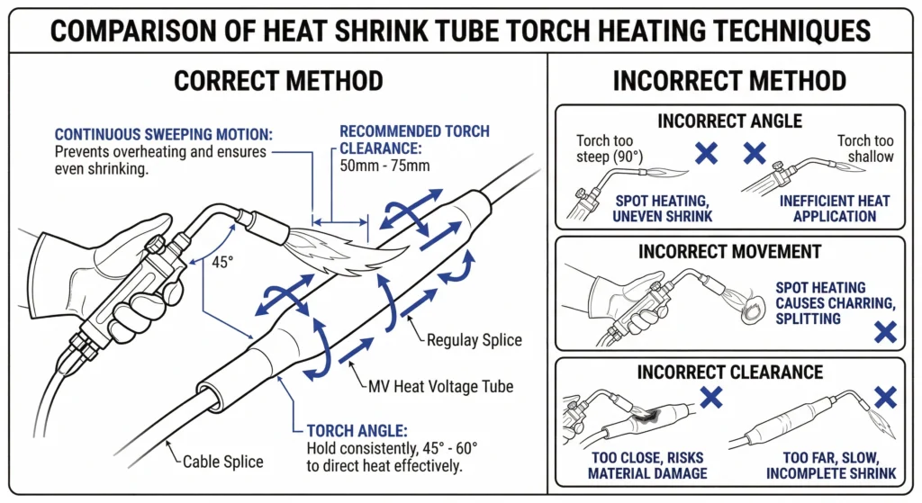
Heating Execution and Shrinkage Control Parameters
FIG-02:Proper thermal execution requires a soft, yellow-tipped flame kept in continuous motion to prevent polymer degradation.
Translating laboratory-grade accessory design into field reliability requires strict thermal execution. During this phase, the installer’s technique directly determines whether the termination achieves its intended service life or fails prematurely. A comprehensive Installation Quality Control Checklist for MV Accessories must rigorously monitor the active heating process.
Torch Technique and Temperature Control
The primary field error during heat shrink installation is improper flame application. Installers must use a soft, bushy propane flame with a yellow tip, explicitly avoiding sharp, blue oxidizing flames that will rapidly scorch and degrade the cross-linked polymer.
The torch nozzle must be held at a consistent distance of 50 mm – 75 mm from the tubing surface.
Experience dictates that the torch must remain in constant, sweeping motion. Lingering on a single spot for more than a few seconds will cause localized overheating. If the tubing surface develops a glossy, blistered, or milky appearance, the molecular structure has been thermally damaged, permanently compromising its tracking resistance and dielectric strength. Installers must continuously rotate the heat 360 degrees around the cable to ensure uniform radial shrinkage and prevent uneven wall thickness, which can create weak points in the insulation barrier.
Tube Positioning and Shrink Sequence
Proper positioning before the application of heat is critical, as a fully shrunk tube cannot be repositioned. The shrinkage sequence dictates the effectiveness of the environmental seal. Heat must invariably be applied starting from the bottom of a termination (or the center of a joint) and swept progressively toward the open ends. This unidirectional shrinking method acts as a mechanical squeegee, forcing air outward and actively driving the underlying stress relief and sealing mastics into every microscopic crevice.
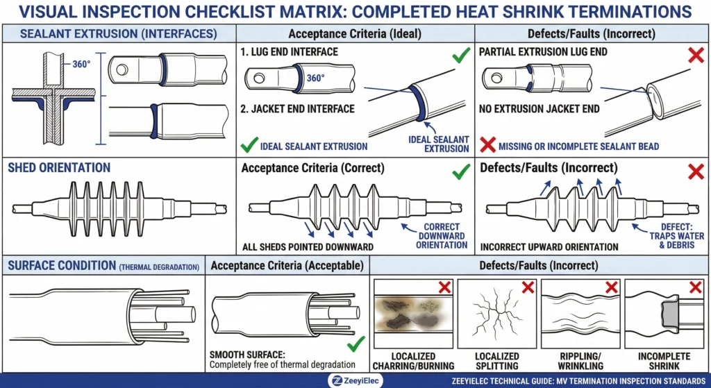
A key visual checkpoint for field inspectors is the behavior of the sealant at the edges of the fully shrunk tube.
A successful installation requires a continuous, 1 mm – 3 mm visible bead of melted mastic extruding from the ends of the tubing onto the cable jacket or terminal lug.
If this extrusion is absent, the environmental seal is incomplete, and moisture ingress will inevitably occur. Once heating is complete, the entire assembly must be allowed to cool naturally to ambient temperature; applying water or cold air to accelerate cooling induces severe thermal shock and internal mechanical stress within the newly formed polymer lattice.
Expert Shrinkage Insights
The Cold Spot Trap: The underside of horizontally mounted cables often receives less heat during shrinking, leading to incomplete mastic extrusion. Always use an inspection mirror to verify the bottom radius is fully sealed.
Directional Shrinkage Rule: Never heat from both ends simultaneously toward the middle. This traps a pocket of air internally, virtually guaranteeing a future partial discharge failure.
Post-Heat Protection: Do not move or bend the completed cable joint until the accessory has fully cooled to ambient temperature, as the mastic layers are still semi-liquid and can separate if disturbed.
Post-Installation Visual Inspection and Electrical Testing
FIG-03:A continuous 1mm to 3mm mastic extrusion at the component boundaries confirms a hermetic environmental seal has been established.
After the heat shrink accessory has fully cooled to ambient temperature, field personnel must execute a stringent post-installation quality control sequence. This phase is the final barrier preventing a compromised installation from being energized. It consists of two non-negotiable stages: a visual defect audit and instrumental electrical testing.
Critical Visual Defect Identification
Visual inspection isolates gross installation errors before any voltage is applied. Inspectors must verify the physical integrity of the outer tubing. The surface must be entirely smooth; any localized blistering, scorch marks, or milky discoloration indicates thermal degradation of the cross-linked polymer.
As previously noted, a continuous mastic extrusion of 1 mm – 3 mm must be visible at both the lug interface and the cable jacket boundary to guarantee a hermetic seal
If the tubing edge has split—often caused by a microscopic nick during staging, uneven heating, or exceeding the maximum shrink ratio—the entire accessory must be rejected and replaced. Furthermore, for outdoor applications, the termination sheds (rain skirts) must be uniformly spaced and oriented correctly downward to shed water efficiently and prevent continuous surface tracking paths.
Mandatory Field Electrical Tests
Once visual acceptance is confirmed, instrumental testing verifies the dielectric integrity of the completed assembly.
The first step is an Insulation Resistance (IR) test, commonly performed with a 2.5 kV or 5 kV Megger. For a healthy 15 kV or 25 kV termination, the measured insulation resistance should typically exceed 1000 MΩ.A standard VLF test applies an AC voltage (typically 0.1 Hz) at 2 × to 3 × the nominal phase-to-ground voltage (U0) for 15 to 30 minutes.
If the termination sustains this elevated electrical stress without tripping the test equipment or demonstrating erratic leakage current, the field engineer can confidently certify the accessory for safe energization and long-term service in the distribution network.
ZeeyiElec Heat Shrink Solutions and Project Support
Comprehensive Energy Interface Matrix
ZeeyiElec engineers reliable Cable Accessories tailored for utility and industrial distribution networks. Our heat shrink portfolio encompasses 10kV, 20(24)kV, and 35kV termination and jointing kits, accommodating conductor cross-sections up to 800 mm2. By strictly matching physical dimension sheets and dielectric parameters, each kit is structured to simplify field execution while guaranteeing long-term insulation stability. Sourcing from a specialized manufacturer means field tolerances and material stress thresholds are actively accounted for long before the components reach the site trench.
Connect with Our Engineering Team
Procurement and field engineering teams require technical certainty alongside seamless installation execution. Beyond cable connections, we supply highly engineered Transformer Accessories to ensure complete network reliability from the primary substation down to the load center. Whether specifying indoor terminations for constrained switchgear or robust transformer protection components, our engineering support guarantees precise model matching and standards-compliant integration. Reach out to our specialized engineering team to secure the right specifications, troubleshoot field challenges, and optimize your next electrical infrastructure project
Frequently Asked Questions
What is the acceptable temperature range for installing heat shrink cable accessories?
Installations should ideally occur between 0°C and 40°C, though pre-heating the cable jacket is required if ambient temperatures drop below 5°C. Extreme cold can make components brittle and prevent proper mastic flow, so localized heating enclosures are necessary in freezing field conditions.
How much overlap is required for mastic tape in heat shrink terminations?
Standard installation requires a 50 percent half-lap wrapping technique extending at least 10 to 15 mm over the adjacent cable layers to ensure a moisture-proof environmental seal. Proper tension must be applied during wrapping; otherwise, thermal cycling and mechanical stress can cause void formation over the accessory’s lifespan.
Why do heat shrink tubes sometimes split during installation?
Splitting typically occurs due to localized overheating exceeding 250°C, uneven torch movement, or existing physical nicks on the edge of the tubing prior to shrinking. Maintaining a continuous, sweeping torch motion and starting the heat from the center or specified end minimizes this risk during field execution.
What is the correct field test voltage for a completed 15kV heat shrink termination?
Field acceptance testing typically utilizes VLF (Very Low Frequency) AC testing or DC high-potential testing, often reaching 25 kV to 35 kV depending on the specific cable age and prevailing utility network protocol. Always consult the specific project testing matrix, as exceeding baseline voltage limits can degrade otherwise healthy polymer insulation.
How long should you wait before energizing a newly installed heat shrink joint?
While heat shrink polymeric materials cure and set almost immediately as they cool to ambient temperature (usually within 30 to 60 minutes), energization should only occur after all mandatory electrical acceptance tests have explicitly passed. Unlike fluid-filled systems, there is no prolonged degassing or settling period required for the solid polymers themselves
yoyo shi
Yoyo Shi writes for ZeeyiElec, focusing on medium-voltage accessories, transformer components, and cable accessory solutions. Her articles cover product applications, technical basics, and sourcing insights for global electrical industry buyers.