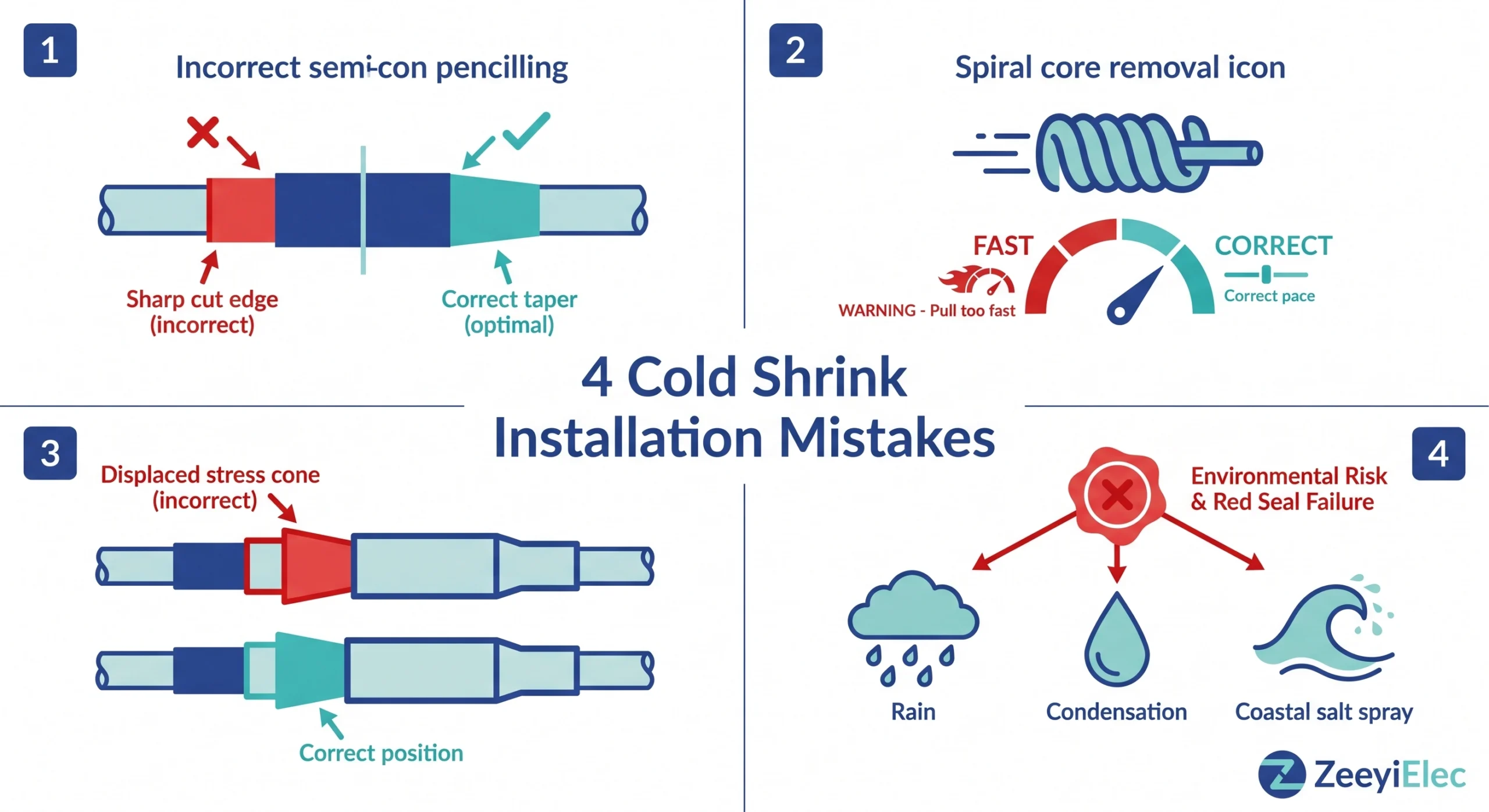
Fehler bei der Kaltschrumpf-Installation lassen sich in vier Kategorien einteilen: Fehler bei der Kabelvorbereitung, Fehler bei der Aderentfernung, Verschiebung des Spannungskegels und Fehler bei der Versiegelung in der Umgebung. Jeder dieser Fehler führt zu einem bestimmten Ausfallmechanismus, der bei Standard-Inbetriebnahmeprüfungen möglicherweise nicht sofort erkannt wird. Das Erkennen und Beheben dieser Fehler vor der Inbetriebnahme ist die wichtigste Maßnahme, die ein Installationsteam ergreifen kann, um die Zuverlässigkeit eines Mittelspannungskabelsystems zu schützen.
Warum Fehler bei der Kaltschrumpf-Installation zu unverhältnismäßig vielen Ausfällen führen
Ein Kaltschrumpfanschluss sieht täuschend einfach aus: Man schiebt den vorgedehnten Silikonschlauch über das vorbereitete Kabelende, entfernt den Spiralkern, und schon scheint die Arbeit erledigt. Diese Einfachheit ist es, die Kaltschrumpfung unversöhnlich gegenüber Abkürzungen macht.
Kaltschrumpf-Zubehörteile werden hergestellt, indem Silikongummi mit einer typischen Shore-A-Härte von 35-55 (ein Maß für die Elastomersteifigkeit) auf das Zwei- bis Dreifache seines entspannten Durchmessers gedehnt wird, wobei ein abnehmbarer Spiralkern das Zubehör während des Transports offen hält. Wenn der Kern vor Ort entfernt wird, erzeugt die gespeicherte elastische Energie einen anhaltenden radialen Druck von typischerweise 0,03-0,15 MPa, abhängig von der Konstruktion des Zubehörs und dem Kabeldurchmesser, der Luftspalten an der Schnittstelle zwischen Silikon und Kabelisolierung beseitigt. Luftspalten sind der Hauptauslöser für Teilentladungen (örtliche elektrische Entladungen, die die Isolierung schrittweise abbauen) bei Mittelspannung. Wenn ein Installationsparameter außerhalb der Toleranz liegt, ist das gesamte Stressmanagementsystem gefährdet, und eine gefährdete Schnittstelle besteht oft die ersten Hochtemperaturtests, bevor sie unter thermischen Zyklen über 12-36 Monate nach und nach versagt.
Wie der Stresskegel funktioniert
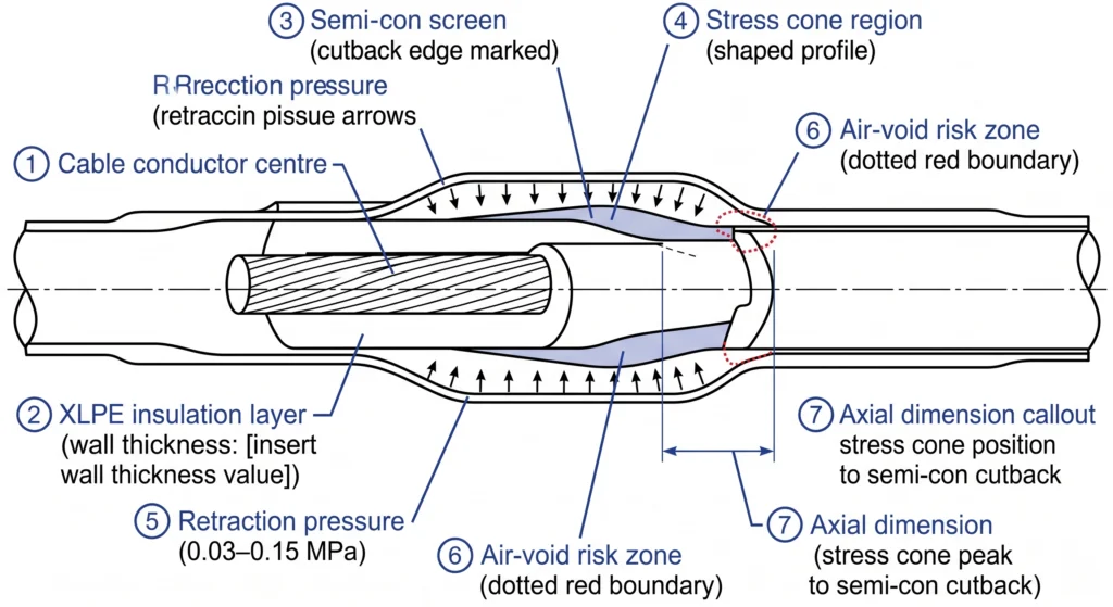
Im Inneren jeder Mittelspannungs-Kaltschrumpfmuffe sorgt ein geometrisch präziser Spannungskegel, ein geformter Bereich aus Silikon mit höherer Leitfähigkeit, für eine Umverteilung der elektrischen Feldkonzentration an der Rückschnittstelle des halbleitenden Schirms (Semi-Con) des Kabels. Seine axiale Position im Verhältnis zum Semi-Con-Cutback wird durch die interne Geometrie des Zubehörs und die Kabelvorbereitung des Installateurs bestimmt. Wenn sich das Zubehörteil axial verschiebt oder die Kabelvorbereitungsmaße außerhalb der Spezifikation liegen, landet der Spannungskonus in der falschen Position und die Feldspitze, für die er ausgelegt ist, bleibt ungemildert.
Abb.-01: Querschnittsschema eines Mittelspannungs-Kaltschrumpfabschlusses, das die axiale Position des Spannungskegels im Verhältnis zum Semi-Con-Cutback-Punkt, die Kompressionszonen der Silikonwand und die Vektoren des Rückzugsdrucks zeigt, die für die Unterdrückung von Grenzflächenhohlräumen maßgeblich sind.
Fehlerkategorie 1 - Fehler bei der Kabelvorbereitung
Die Kabelvorbereitung ist die Grundlage jeder Kaltschrumpfinstallation - Maßfehler sind hier nach dem Entfernen der Ader nur selten korrigierbar. Felddaten aus Mittelspannungsprojekten zeigen, dass Fehler bei der Kabelvorbereitung die Hauptursache für vorzeitige Kaltschrumpfausfälle sind. Sie sind für etwa 35-45% der zubehörbedingten Ausfälle innerhalb der ersten fünf Betriebsjahre verantwortlich.
Falscher Winkel und falsche Länge des Semi-Con Pencillings
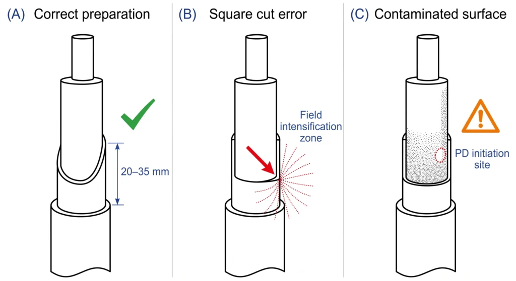
Während in den Spezifikationen je nach Spannungsklasse in der Regel ein Bleistiftkonus von 20-35 mm vorgeschrieben ist, schneiden Außendienstmitarbeiter unter Zeitdruck den Halbkonus häufig ab oder bringen eine kurze Fase von 5-10 mm an. Bei der Spannungsklasse 15 kV kann diese scharfe Kante die lokale Feldspannung um den Faktor zwei oder mehr über den vorgesehenen Wert erhöhen. Die Prüfung mit der Fingerspitze bestätigt die korrekte Technik: eine korrekt mit Bleistift gezeichnete Kante fühlt sich wie eine glatte Rampe ohne erkennbare Stufe zwischen Semi-Con und Isolationsflächen an.
Verunreinigung der Dämmstoffoberfläche vor der Anbringung des Zubehörs
Eine Verschmutzungsschicht, die nur wenige Mikrometer dünn ist, verhindert einen innigen Silikonkontakt. Ein Ausfall eines 15-kV-Außenanschlusses 14 Monate nach der Einschaltung wurde auf Kohlenstoffspuren an der Isolationsoberfläche zurückgeführt, die das Personal mit einem trockenen Tuch statt mit dem vorgeschriebenen Lösungsmittel gereinigt und nicht unter Schräglicht geprüft hatte. Bei der Inbetriebnahme wurde ein 10 kV DC-Hi-Pot-Test durchgeführt; sechs Monate später wurde bei Teilentladungsprüfungen eine messbare Aktivität bei 8 kV festgestellt. Korrekte Vorgehensweise: Lösungsmittelreinigung mit einem zugelassenen fusselfreien Tuch in einer Richtung, gefolgt von einer Inspektion unter Schräglicht.
Leiterexposition außerhalb des spezifizierten Bereichs
Das Überkleben hinterlässt einen ungeschützten Isolationsbereich zwischen dem Zubehör und dem Kabelschuhkörper, der bei Temperaturschwankungen zu Teilentladungen und Feuchtigkeitseintritt führen kann. Die Unterabdeckung verhindert den vollständigen Sitz der Kabelschuhe und schafft einen thermischen Hotspot, der die Alterung der Isolierung an der mechanisch am stärksten belasteten Stelle des Anschlusses beschleunigt.
Abb.-02: Drei Zustände der Kabelvorbereitung für die Kaltschrumpfverbindung im Mittelspannungsbereich: Feld A zeigt einen korrekt mit Bleistift gezeichneten Halbkonus (20-35 mm); Feld B zeigt eine quadratisch geschnittene Halbkonuskante, die eine Verstärkung des elektrischen Feldes bewirkt; Feld C zeigt eine kontaminierte Isolationsoberfläche mit teilweiser Entladungsauslösung an der Silikongrenzfläche.
Halbkonuslänge: anhand des Datenblattes des Bausatzes überprüfen; 20-35 mm ist typisch für die 15 kV-Klasse, länger für 35 kV
Trocknungszeit des Lösungsmittels: mindestens 2-5 Minuten zwischen Reinigung und Anbringung des Zubehörs - nicht 30 Sekunden
Halten Sie den Isolations-AD, die Semi-Con-Cutback-Länge und die Leiterfreilegung im Installationsprotokoll fest, bevor Sie mit der Aderentfernung beginnen.
Fehlerkategorie 2 - Fehler bei der Kernentnahme und Positionierung
Fehler bei der Kernentfernung sind besonders folgenreich, da sie keine äußeren Spuren hinterlassen. Ein verschobener Spannungskonus sieht von außen genauso aus wie ein korrekt installierter Abschluss, bis es zum Bruch kommt.
Zu schnelles Ziehen des Spiralkerns
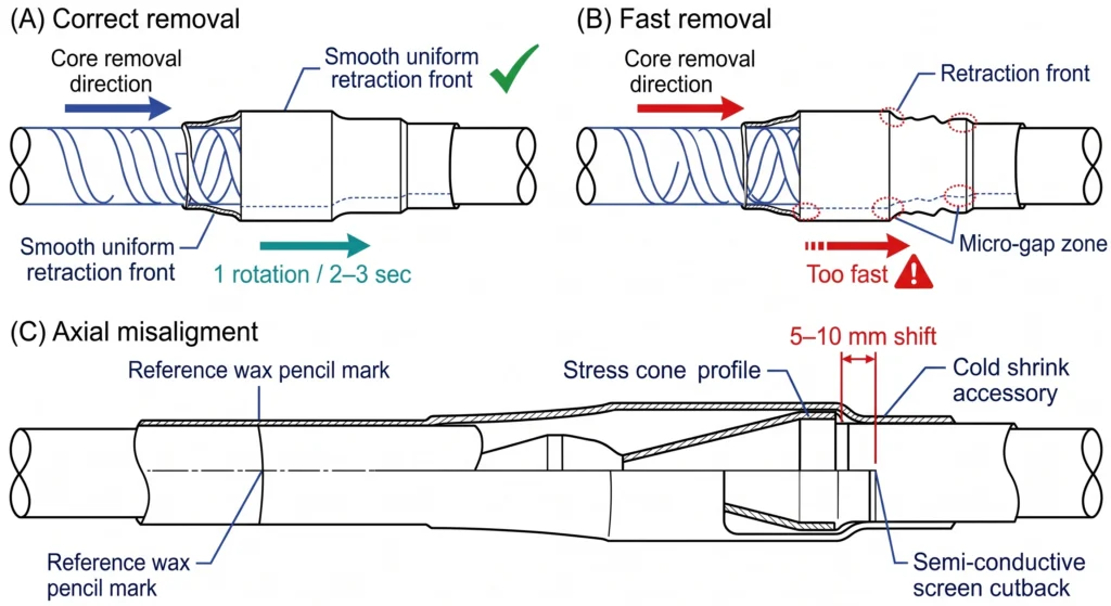
Der Kern muss etwa alle 2-3 Sekunden mit einer vollen Umdrehung abgewickelt werden. Ein zu schnelles Abziehen führt zu lokalen Mikrospalten an der Schnittstelle zwischen Silikon und Isolierung, die klein genug sind, um die Hochspannung bei der Inbetriebnahme zu überstehen, und groß genug, um unter Betriebsbedingungen eine Teilentladung auszulösen. Bei 35-kV-Abschlüssen mit Kontaktlängen von mehr als 200 mm dauert das korrekte Entfernen des Kerns 60-90 Sekunden; Mannschaften, die unter Zeitdruck stehen, erledigen dies routinemäßig in weniger als 15 Sekunden.
Fehlausrichtung des Zubehörs vor Beginn der Kernentfernung
Positionieren Sie das Zubehörteil genau an der in der Montageanleitung angegebenen axialen Position, gemessen von der Semi-Con-Cutback, und überprüfen Sie diese, bevor Sie den Kern berühren. Sobald der Rückzug beginnt, ist eine Neupositionierung nicht mehr möglich. Selbst eine axiale Verschiebung von 5-10 mm bei der 15-kV-Klasse führt dazu, dass die Spitze des Spannungskegels außerhalb der Semi-Con-Kantenbegrenzung liegt. Zuverlässige Überprüfung vor dem Entfernen: Markieren Sie die Zielposition mit einem Wachsstift, bevor Sie das Zubehörteil an seinen Platz schieben.
Installation bei kalten Temperaturen ohne Vorkonditionierung
Unter -10°C weisen einige Silikonformulierungen eine vorübergehende Versteifung auf, die die Rückstellkraft während des Installationsfensters um 20-40% reduziert. Eine 35-kV-Kaltschrumpfmuffe, die bei -8°C Umgebungstemperatur ohne Vorkonditionierung installiert wurde, bestand die Inbetriebnahmeprüfung; bei der routinemäßigen Wartung 14 Monate später wurde eine Teilentladung festgestellt, wobei die Anfangsspannung etwa 18% unter dem Auslegungsgrenzwert des Herstellers lag. Korrektur: Lagern Sie das Zubehör bei mindestens 15°C für mindestens vier Stunden vor der Installation, wenn die Umgebungstemperatur unter 5°C liegt.
Abb.-03: Spiralförmige Kernentfernungssequenz für einen Mittelspannungs-Kaltschrumpfabschluss: Feld A zeigt die korrekte, kontrollierte Entfernung mit gleichmäßiger Silikon-Rückzugsfront; Feld B zeigt die beschleunigte Entfernung, die zu lokalen Mikrospaltzonen führt; Feld C zeigt die axiale Fehlausrichtung, die zu einer Verschiebung des Spannungskonus relativ zur Semi-Cutback-Grenze führt.
Fehlerkategorie 3 - Versagen von Spannungskegeln und Isolationsschnittstellen
Bei der 15-kV-Klasse kann ein um 8-10 mm aus seiner vorgesehenen axialen Position verschobener Spannungskonus die Spitzenbelastung des elektrischen Feldes an der Halbkonuskante um 30-60% über das vorgesehene Maximum hinaus erhöhen - eine Marge, die bei Lastwechseln und transienten Überspannungen allmählich erodiert, bevor die Teilentladungs-Eingangsspannung unter den Dauerbetriebsbereich fällt.
Eingeschlossene Luftporen verstärken dieses Risiko. Luft hat eine Durchschlagfestigkeit von ca. 3 kV/mm unter gleichmäßigen Feldbedingungen - ein Bruchteil der 20-30 kV/mm, die eine gut verklebte Silikon/XLPE-Schnittstelle aufweist. Hohlräume entstehen durch Oberflächenverunreinigungen, unvollständige Kaltschrumpfung und Lösungsmittelreste von Reinigungsmitteln, die vor dem Aufbringen des Zubehörs nicht vollständig verdampft sind.
Die Typprüfung qualifiziert das Zubehörsystem unter kontrollierten Laborbedingungen, die nicht die Variabilität der Feldinstallation widerspiegeln. Die Anforderungen an die Schnittstellenqualifizierung für Mittelspannungs-Kaltschrumpfzubehör, einschließlich der Teilentladungsgrenzen während der Typprüfung, sindgezeichnet von IEC 60502-4.
Die Messung der Teilentladung bei der 1,0- bis 1,5-fachen Systemspannung zwischen Phase und Erde ist der zuverlässigste Qualitätsindikator nach der Installation. Ein Ergebnis von mehr als 10-20 pC bei Betriebsspannung ist ein dokumentierter Defekt in der Installationsphase, unabhängig vom optischen Erscheinungsbild bei Fertigstellung.
Fehlerkategorie 4 - Umwelt- und Versiegelungsfehler
Ein Kaltschrumpfabschluss mit korrekter interner Schnittstellengeometrie kann dennoch an seinen äußeren Grenzen versagen. Das Eindringen von Feuchtigkeit durch die Mantelabdichtung kann zwei bis vier Jahre dauern, bevor die leitende Front die Kabelisolierung erreicht, und der daraus resultierende Ausfall ist nicht von einem Defekt an der Schnittstelle während der Installation zu unterscheiden.
Fehler in der Reihenfolge der Anwendung von Dichtungsmassen
Mastix ist die primäre Feuchtigkeitsbarriere an der Verbindung zwischen Schrumpfschlauch und Mantel. Die beiden häufigsten Fehler sind die Umkehrung der Reihenfolge, d. h. das Auftragen von Mastix nach dem Anbringen des Zubehörs statt an der Manteloberfläche davor, und das Überdehnen des Bandes auf weniger als 70-80% seiner entspannten Dicke. Bei profilierten Kabelmänteln sind mindestens zwei halb überlappende Lagen erforderlich, um Oberflächenhohlräume zu füllen.
Feuchtigkeitsverschmutzung bei intervalloffener Verlegung
Sechs im Freien installierte Endverschlüsse, die während eines Küstennebelereignisses installiert wurden, wiesen 14 Monate nach der Inbetriebnahme bei vier der sechs Endverschlüsse Feuchtigkeitsverfolgungsmuster auf - alle sechs bestanden bei der Inbetriebnahme den 10 kV DC-Hi-Pot. Die beiden nicht betroffenen Endverschlüsse wurden installiert, nachdem sich der Nebel verzogen hatte. Unterbrechen Sie die Installation, wenn die relative Luftfeuchtigkeit 80% übersteigt oder wenn sichtbare Kondensation auf einer Kabel- oder Zubehöroberfläche vorhanden ist.
Kontamination in stark verschmutzten oder küstennahen Umgebungen
Silikon hat eine ausgezeichnete Kriechstrom- und Erosionsbeständigkeit, aber nur, wenn die Außenfläche unbeschädigt und sauber bei der Außenmontage ankommt. Ein Überfließen von Mastix auf die Shed-Oberfläche oder eine physische Beschädigung während der Installation in engen Räumen reduziert die effektive Kriechstrecke - die Weglänge entlang der Isolatoroberfläche, die der Oberflächenverfolgung bei nasser Verschmutzung widersteht - ohne dass es nach der Installation einen visuellen Indikator gibt. Die Anforderungen an die Klassifizierung des Verschmutzungsgrads von Dämmstoffen für den Außenbereich sind unterIEC 60815.
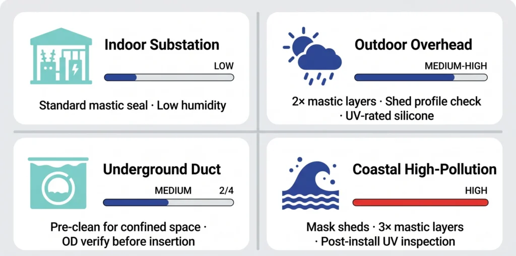
Abb.-04: Matrix der Umweltrisikozonen für Kaltschrumpfkabelanschlüsse und -muffen, die die Abdichtungsanforderungen und den Grad der Kontaminationsbelastung in Innenräumen von Umspannwerken, Freileitungen im Freien, unterirdischen Kanälen und in Küstengebieten mit hoher Verschmutzung klassifiziert.
Feuchtigkeitsschwelle: Aufhängen der Kabelvorbereitung mit offenem Intervall über 80% RH am Installationsort
Mindestens zwei halb überlappende Schichten auf profilierten Mantelflächen; drei auf gewellten Profilen
Schutz der Shed-Oberfläche: Abdecken der Shed-Profile mit einer sauberen Polyethylenfolie während des Auftragens des Mastix, um eine Verunreinigung durch Überlaufen zu verhindern
Pass/Fail-Inspektion vor der Einschaltung
Die strukturierte Prüfung vor der Erregung fängt die nachweisbare Untergruppe von Installationsfehlern auf und schafft eine überprüfte Maßbasis für jede zukünftige Fehleruntersuchung.
Visuelle und dimensionale Kontrollpunkte
Kontrollpunkt
Kriterien für das Bestehen
Gemeinsamer Fehlerindikator
Semi-con cutback Qualität
Glatte Verjüngung 20-35 mm; keine Stufe an der Fingerspitze
Scharfe Kante; Kohlenstoffrückstände an der Kegelgrenze
Zustand der Isolationsoberfläche
Sauber, trocken, keine Verschmutzung unter schräger Beleuchtung
Referenzmarkierung an der richtigen Stelle in Bezug auf den Semi-Cutback
Markierung fehlt; Zubehör >5 mm verschoben
Bestätigung der Entkernung
Spirale vollständig entfernt; kein Fragment im Zubehörkörper
Kernsegment sichtbar; teilweise Retraktionszone vorhanden
Äußere Silikonoberfläche
Keine Schnitte, Einstiche oder Schuppenschäden; kein Kitt auf Schuppenprofilen
Werkzeugkontaktspuren; mit Kitt verunreinigte Schuppen
Integrität der Mastix-Dichtung
Mindestens zwei halb überlappende Lagen; keine Lücken am Überlappungsrand
Einlagig mit durch den Mastix sichtbarer Manteloberfläche
Vor dem Anbringen des Zubehörs sind drei Maße anhand des Datenblattes des Bausatzes zu überprüfen und aufzuzeichnen: der Außendurchmesser der Kabelisolierung an drei axialen Positionen mit einem kalibrierten Messschieber, die Länge des Halbkonus und die Länge des freiliegenden Leiters. Diese Messungen dauern weniger als vier Minuten und bilden die Grundlage für die Rückverfolgbarkeit der Abmessungen während der Lebensdauer des Zubehörs.
Elektrische Vor-Energisierungstests
Isolationswiderstand bei 2,5-5 kV DC für 60 Sekunden (mindestens >1.000 MΩ) prüft auf grobe Fehler, Feuchtigkeitsverschmutzung, Oberflächenverfolgung, unbeabsichtigte Leiterfreilegung. Wenn Teilentladungsprüfungen verfügbar sind, die bei Projekten der 35-kV-Klasse zunehmend zum Standard werden, ist ein Ergebnis, das keine messbare Aktivität über 10-20 pC bei der 1,0- bis 1,5-fachen Betriebsspannung zeigt, das Kriterium für das Bestehen der Vorerregung mit der höchsten Zuverlässigkeit, das im Feld verfügbar ist. Jedes einzelne Versagen eines Kontrollpunktes ist ein Grund für den Ausbau und die Neuinstallation des Zubehörs, nicht für eine Korrektur vor Ort.
Wie man das richtige Kaltschrumpfset auswählt, um das Risiko von Installationsfehlern zu verringern
Mit einem korrekt abgestimmten Bausatz erhält der Installateur ein System, das auf Erfolg ausgelegt ist. Die Vollständige Auswahlkarte für Kabelzubehör deckt den gesamten Spezifikationsprozess ab. In diesem Abschnitt werden die Parameter isoliert, die am unmittelbarsten mit den oben genannten Fehlermöglichkeiten in Verbindung stehen.
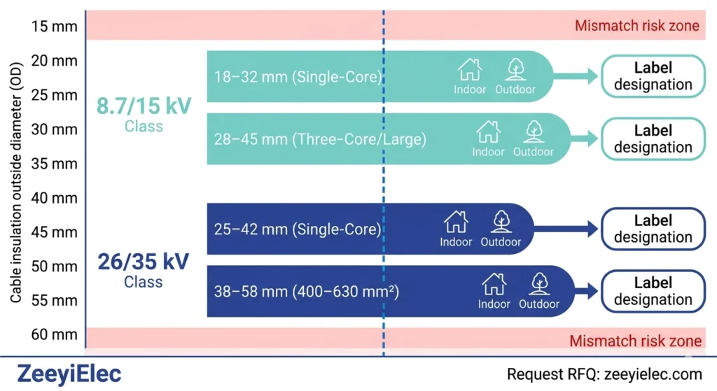
Kabel-AD-Bereich und Spannungsklassenanpassung
Spannungsklasse
Typischer Isolations-AD-Bereich
Logik der Tastenauswahl
8,7/15 kV
18-32 mm (einadriges XLPE)
Wählen Sie den Satz, dessen OD-Mittelpunkt dem gemessenen Kabel-AD am nächsten liegt.
8,7/15 kV
28-45 mm (dreiadriger oder großer Leiter)
Prüfen Sie den OD pro Kern für Verbindungen; den OD einzelner Kerne für Abschlüsse
26/35 kV
25-42 mm (einadriges XLPE)
Engeres Toleranzband - die OD-Anpassung im mittleren Bereich ist bei dieser Klasse kritischer
26/35 kV
38-58 mm (400-630 mm² Leiter)
Bestätigen Sie die Wandstärke der Isolierung anhand des Kabeldatenblatts; 9-12 mm Wandstärke sind bei dieser Klasse typisch.
Anschlusstyp, Umgebung und Isolationsverträglichkeit
Die Bezeichnungen für Innen- und Außenbereich sind nicht austauschbar. Ein für den Innenbereich zugelassener Anschluss, der im Außenbereich installiert wird, eliminiert die für die Spannungsklasse erforderliche Kriechstrecke, unabhängig von der Qualität des Installationsverfahrens. Die Kompatibilität des Isoliermaterials ist ebenso wichtig: Kaltschrumpfendes Zubehör, das für XLPE (Dielektrizitätskonstante typischerweise 2,2-2,4) typgeprüft ist, ist nicht für EPR-Isolierung (Dielektrizitätskonstante typischerweise 2,8-3,5) geeignet, ohne dass eine separate Überprüfung anhand der Qualifikationsdaten des Herstellers erfolgt. Bestätigen Sie beide Parameter, bevor Sie die Bestellung abschließen - nicht nach der Lieferung.
Das Kaltschrumpfkabel-Zubehör von ZeeyiElec deckt die Spannungsbereiche 8,7/15 kV und 26/35 kV ab, mit Anschlussoptionen für den Innen- und Außenbereich und durchgehenden Verbindungsgarnituren, die mit Maßtoleranzen entwickelt wurden, die das Risiko von Montagefehlern vor Ort reduzieren.
Abb. 05: Auswahlmatrix für Kaltschrumpfkits, die die Bereiche der Kabelisolationsaußendurchmesser den Spannungsklassen (8,7/15 kV und 26/35 kV) zuordnet, mit Bezeichnungen für Innen- und Außenanschlüsse für einadrige und mehradrige Konfigurationen.
Häufig gestellte Fragen
Was ist der häufigste Fehler bei der Installation von Kaltschrumpfgeräten?
Der am häufigsten dokumentierte Fehler ist ein falsches Semi-Con-Pencilling, bei dem die Abschirmung quadratisch geschnitten oder zu kurz verjüngt wird, so dass ein scharfer dielektrischer Spannungskonzentrationspunkt zurückbleibt, den der innere Spannungskegel nicht umverteilen kann. Dies führt in der Regel innerhalb von 12-36 Monaten zu einer messbaren Teilentladungsaktivität, je nach Spannungsklasse und Häufigkeit der Lastwechsel.
Wie kalt muss es sein, damit die Kaltschrumpfmontage besondere Vorsichtsmaßnahmen erfordert?
Vorkonditionierungsprotokolle werden in der Regel bei Temperaturen unter 5°C empfohlen, da die Rückstellkraft und die Rückstellgeschwindigkeit des Silikons bei Temperaturen nahe dem Gefrierpunkt abnehmen, was das Risiko eines unvollständigen Sitzes der Schnittstelle erhöht, die zwar den Hi-Pot-Test bei der Inbetriebnahme besteht, aber bei kontinuierlicher Betriebsspannung eine Teilentladung auslöst.
Kann ein Kaltschrumpfzubehörteil neu positioniert werden, nachdem der Spiralkern teilweise entfernt wurde?
Eine Neupositionierung nach Beginn der Retraktion ist nicht empfehlenswert, da sich das Silikon bereits an der Retraktionszone anpasst und jede axiale Verschiebung den inneren Spannungskonus aus seiner vorgesehenen Beziehung mit der Semi-Cutback-Kante verschiebt, was eine vollständige Entfernung und Neuinstallation des Zubehörs erfordert.
Wie lange sollte man warten, bevor man nach der Installation von Kaltschrumpfgeräten Strom zuführt?
Eine Stabilisierungszeit von 15-30 Minuten bei Temperaturen über 10°C ist für die Rückgewinnung von Silikonen und Mastix-Amalgamation weit verbreitet und kann sich bei Kälte oder hoher Luftfeuchtigkeit auf 45-60 Minuten verlängern, obwohl das maßgebliche Kriterium immer die Installationsanweisung des Herstellers des jeweiligen Kits sein sollte, da die Silikonformulierungen in den verschiedenen Produktfamilien unterschiedlich sind.
Führt eine Verschmutzung der Kabeloberfläche immer zu einem sofortigen Ausfall?
Verunreinigungen an der Schnittstelle zwischen Silikon und Isolierung führen selten zu einem sofortigen Ausfall. Die meisten verunreinigten Anlagen bestehen die Standard-Hi-Pot-Tests bei der Inbetriebnahme, aber die Schicht erzeugt Teilentladungsauslösungsstellen, die die Schnittstelle nach und nach degradieren, wobei Ausfälle typischerweise 6-24 Monate nach der Inbetriebnahme auftreten und häufig fälschlicherweise auf Materialfehler zurückgeführt werden.
Was ist die richtige Geschwindigkeit für das Entfernen von Spiralkernen bei Kaltschrumpfzubehör?
Eine volle Spiralumdrehung alle 2-3 Sekunden ist die gängige Praxis für Kaltschrumpfzubehör im Mittelspannungsbereich, so dass sich die Rückzugsfront gleichmäßig fortbewegen und einen vollständigen Schnittstellenkontakt erreichen kann, bevor der nächste Abschnitt freigegeben wird. Bei Abschlüssen der 35-kV-Klasse sind 60-90 Sekunden für die gesamte Sequenz erforderlich.
Fällt Kaltschrumpfzubehör im Freien anders aus als unter Tage?
Ja ~ im Außenbereich entstehen Ausfälle am häufigsten an der Wetterdichtung und dem Schuppenprofil unter UV-Belastung und feuchten Verschmutzungsbedingungen, während Ausfälle im Erdreich und in Schaltanlagen typischerweise an der internen Silikon-Dämmungs-Schnittstelle durch Verunreinigungen oder Maßabweichungen bei der Installation in beengten Umgebungen entstehen.
Yo-Yo-Shi
Yoyo Shi schreibt für ZeeyiElec und konzentriert sich dabei auf Mittelspannungszubehör, Transformatorenkomponenten und Kabelzubehörlösungen. Ihre Artikel behandeln Produktanwendungen, technische Grundlagen und Einblicke in die Beschaffung für Einkäufer der globalen Elektroindustrie.