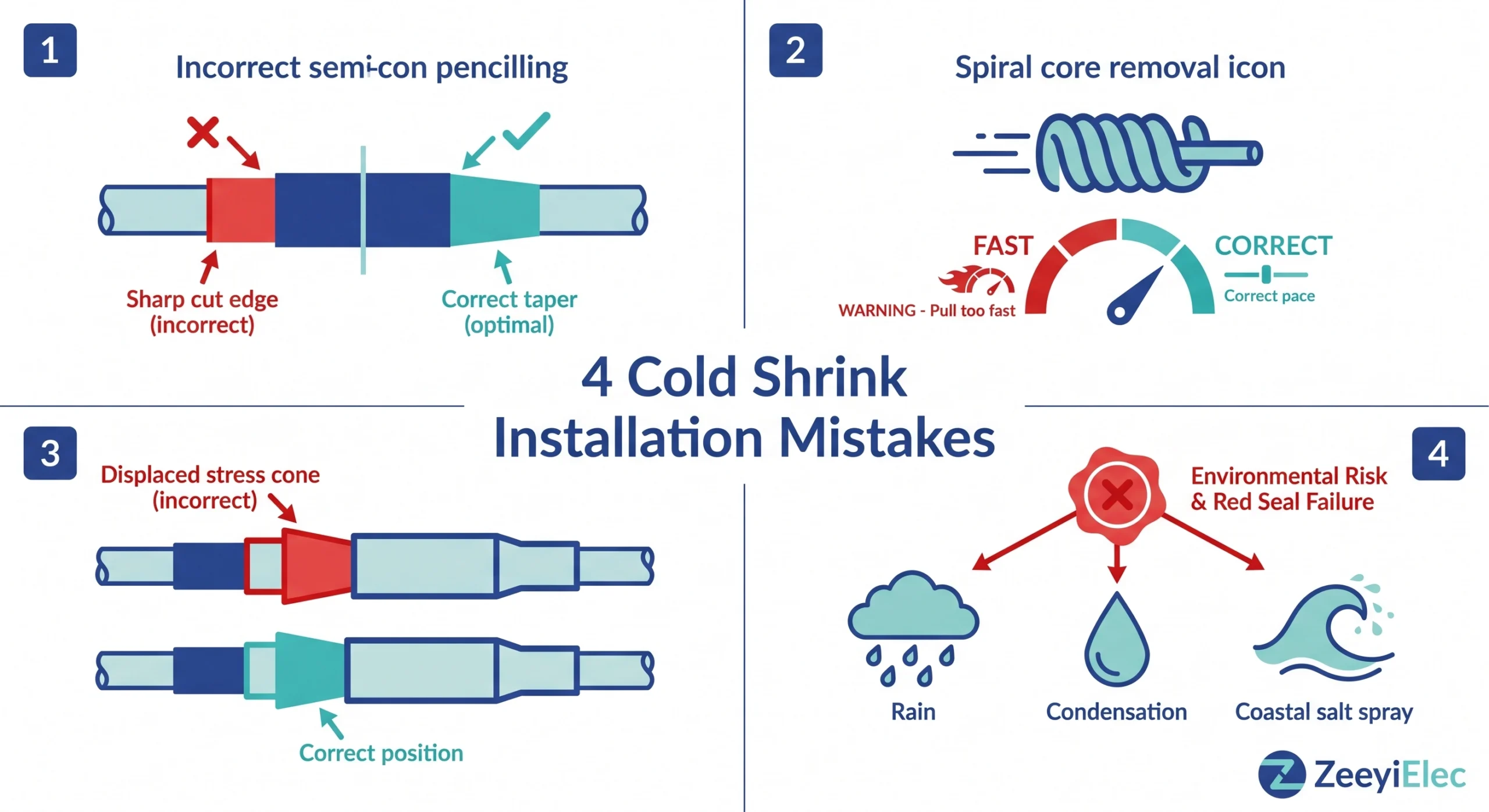
Os erros de instalação de encolhimento a frio se enquadram em quatro categorias: erros de preparação do cabo, erros de remoção do núcleo, deslocamento do cone de tensão e falhas de vedação ambiental. Cada um deles introduz um mecanismo de falha distinto que os testes de comissionamento padrão podem não detectar imediatamente. Identificar e corrigir esses erros antes da energização é a ação de maior impacto que uma equipe de instalação pode tomar para proteger a confiabilidade do sistema de cabos de média tensão.
Por que os erros de instalação do Cold Shrink causam falhas desproporcionais
Uma terminação por encolhimento a frio parece enganosamente simples: deslize o tubo de silicone pré-expandido sobre a extremidade do cabo preparado, remova o núcleo espiralado e o trabalho parece concluído. Essa simplicidade é o que faz com que a contração a frio não perdoe atalhos.
Os acessórios de encolhimento a frio são fabricados expandindo a borracha de silicone, normalmente com dureza Shore A 35-55 (uma medida da rigidez do elastômero) para duas a três vezes o seu diâmetro relaxado, com um núcleo espiral removível que o mantém aberto durante o transporte. Quando o núcleo é removido no local, a energia elástica armazenada cria uma pressão radial sustentada, normalmente de 0,03 a 0,15 MPa, dependendo do design do acessório e do diâmetro externo do cabo, que elimina as lacunas de ar na interface silicone-cabo-isolamento. As lacunas de ar são o principal local de início da descarga parcial (descargas elétricas localizadas que degradam o isolamento de forma incremental) em média tensão. Quando um parâmetro de instalação fica fora da tolerância, todo esse sistema de gerenciamento de estresse fica comprometido e uma interface comprometida geralmente passa no teste inicial de alto ponto antes de falhar progressivamente em ciclos térmicos ao longo de 12 a 36 meses.
Como funciona o cone de estresse
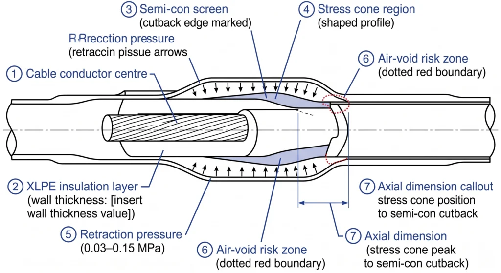
Dentro de cada terminação retrátil a frio de média tensão, um cone de tensão geometricamente preciso, uma região moldada de silicone de maior permissividade, redistribui a concentração do campo elétrico no ponto de corte da tela semicondutora (semicon) do cabo. Sua posição axial em relação ao corte do semicondutor é definida pela geometria interna do acessório e pela preparação do cabo pelo instalador. Se o acessório se deslocar axialmente ou se as dimensões de preparação do cabo estiverem fora da especificação, o cone de tensão cairá na posição errada e o pico de campo que ele foi projetado para gerenciar não será mitigado.
Fig.-01: Esquema de seção transversal de uma terminação de encolhimento a frio de média tensão ilustrando a posição axial do cone de tensão em relação ao ponto de corte do semicondutor, as zonas de compressão da parede de silicone e os vetores de pressão de retração que governam a supressão de vazios na interface.
Categoria de erro 1 - Erros de preparação do cabo
A preparação do cabo é a base de toda instalação de encolhimento a frio - erros dimensionais raramente podem ser corrigidos depois que o núcleo é removido. Dados de campo de projetos de terminação de média tensão colocam os erros de preparação de cabos como a principal causa raiz de falhas prematuras de contração a frio, sendo responsáveis por aproximadamente 35-45% das falhas relacionadas a acessórios nos primeiros cinco anos de serviço.
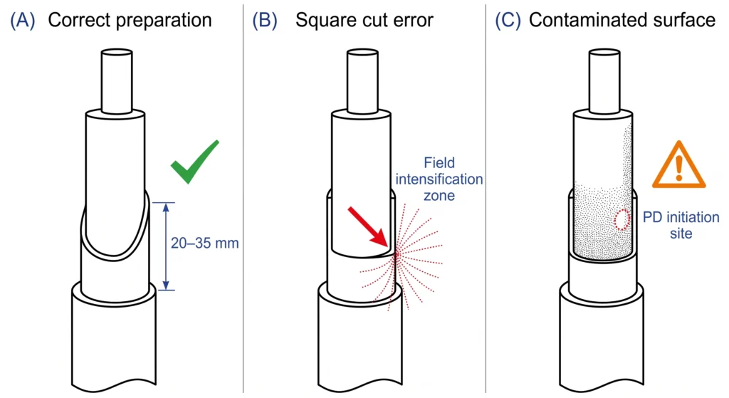
Ângulo e comprimento incorretos do lápis semiconlineador
Quando as especificações normalmente exigem um cone de lápis de 20 a 35 mm, dependendo da classe de tensão, as equipes de campo, sob pressão de tempo, frequentemente cortam o semi-cone quadrado ou aplicam um chanfro curto de 5 a 10 mm. Na classe de 15 kV, essa borda afiada pode aumentar a tensão de campo local por um fator de dois ou mais acima do valor projetado. A verificação com a ponta do dedo confirma a técnica correta: uma borda devidamente desenhada parece uma rampa suave, sem degrau detectável entre as superfícies do semicondutor e do isolamento.
Contaminação da superfície do isolamento antes da colocação do acessório
Uma camada de contaminação tão fina quanto alguns micrômetros impede o contato íntimo com o silicone. Uma falha na terminação externa de 15 kV, 14 meses após a energização, foi atribuída ao rastreamento de carbono na superfície do isolamento que a equipe havia limpado com um pano seco em vez do solvente especificado e não havia inspecionado sob iluminação angular. Ele foi aprovado em 10 kV DC hi-pot no comissionamento; o teste de descarga parcial seis meses depois mostrou atividade mensurável em 8 kV. Prática correta: limpeza com solvente com um pano sem fiapos aprovado em uma direção, seguida de inspeção sob iluminação angular.
Exposição do condutor fora da faixa especificada
O revestimento excessivo deixa uma zona de isolamento desprotegida entre a parte superior do acessório e o corpo do terminal, um local de descarga parcial e de entrada de umidade durante o ciclo térmico. A colocação de fita adesiva impede o assentamento completo do terminal, criando um ponto de acesso térmico que acelera o envelhecimento do isolamento no ponto de maior estresse mecânico da terminação.
Fig.-02: Três estados de preparação do cabo para terminação por contração a frio de média tensão: O painel A mostra um cone semicondutor corretamente preenchido com lápis (20-35 mm); o painel B mostra uma borda semicondutora quadrada que produz intensificação do campo elétrico; o painel C mostra uma superfície de isolamento contaminada com local de início de descarga parcial na interface de silicone.
[Expert Insight] - Padrões de campo para preparação de cabos
Comprimento do cone do semicondutor: verifique a folha de dados do kit; 20 a 35 mm é típico para a classe de 15 kV, mais longo para 35 kV
Tempo de secagem do solvente: mínimo de 2 a 5 minutos entre a limpeza e a aplicação do acessório - não 30 segundos
Registre o diâmetro externo do isolamento, o comprimento do corte do semicondutor e a exposição do condutor no registro de instalação antes de iniciar a remoção do núcleo
Categoria de erro 2 - Erros de remoção do núcleo e de posicionamento
Os erros de remoção do núcleo são particularmente consequentes, pois não deixam vestígios externos. Um cone de tensão deslocado parece idêntico, do lado de fora, a uma terminação instalada corretamente até que ocorra a falha.
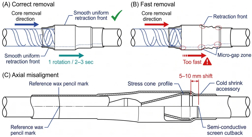
Puxando o núcleo em espiral muito rápido
O núcleo deve ser desenrolado em aproximadamente uma rotação completa a cada 2 ou 3 segundos. Puxar muito rápido produz microfendas localizadas na interface silicone-isolamento, pequenas o suficiente para passar por tensões de alto ponto de comissionamento e grandes o suficiente para iniciar uma descarga parcial em condições de serviço. Em terminações de 35 kV com comprimentos de contato superiores a 200 mm, a remoção correta do núcleo leva de 60 a 90 segundos; as equipes sob pressão do cronograma rotineiramente a concluem em menos de 15 segundos.
Desalinhamento do acessório antes do início da remoção do núcleo
Posicione o acessório no local axial preciso especificado nas instruções de instalação, medido a partir do corte do semicondutor, e verifique antes de tocar no núcleo. Uma vez iniciada a retração, o reposicionamento não é possível. Mesmo um deslocamento axial de 5 a 10 mm na classe de 15 kV coloca o pico do cone de tensão fora do limite da borda do semicondutor. Verificação confiável antes da remoção: marque a posição do alvo com um lápis de cera antes de deslizar o acessório no lugar.
Instalação em temperatura fria sem pré-condicionamento
Abaixo de -10°C, algumas formulações de silicone apresentam endurecimento temporário que reduz a força de recuperação em 20-40% durante a janela de instalação. Uma junta retrátil a frio de 35 kV instalada em ambiente de -8°C sem pré-condicionamento foi aprovada nos testes de comissionamento; a atividade de descarga parcial foi detectada na manutenção de rotina 14 meses depois, com tensão de início aproximadamente 18% abaixo do limite de projeto do fabricante. Correção: armazene os acessórios a no mínimo 15°C por pelo menos quatro horas antes da instalação quando o ambiente estiver abaixo de 5°C.
Fig.-03: Sequência de remoção do núcleo em espiral para uma terminação de encolhimento a frio de média tensão: O painel A ilustra a remoção controlada correta com frente de retração de silicone uniforme; o painel B mostra a remoção acelerada produzindo zonas de microgap localizadas; o painel C demonstra o desalinhamento axial resultando no deslocamento do cone de tensão em relação ao limite de corte semicondutor.
Categoria de erro 3 - Falhas no cone de tensão e na interface de isolamento
Na classe de 15 kV, um cone de tensão deslocado de 8 a 10 mm de sua posição axial projetada pode aumentar a tensão de pico do campo elétrico na borda do semicone em 30-60% acima do máximo projetado, uma margem que se desgasta progressivamente sob ciclos de carga e sobretensões transitórias antes que a tensão inicial de descarga parcial caia abaixo do envelope de operação contínua.
Os vazios de ar aprisionados agravam esse risco. O ar tem uma força dielétrica de aproximadamente 3 kV/mm sob condições de campo uniforme, uma fração da capacidade de 20 a 30 kV/mm de uma interface de silicone para XLPE bem unida. Os vazios se originam de contaminação da superfície, retração incompleta em temperatura fria e solvente residual de agentes de limpeza não totalmente evaporados antes da aplicação do acessório.
O teste de tipo qualifica o sistema de acessórios em condições controladas de laboratório e não reproduz a variabilidade da instalação em campo. Os requisitos de qualificação de interface para acessórios de contração a frio de média tensão, incluindo limites de descarga parcial durante o teste de tipo, sãorned por IEC 60502-4.
A medição de descarga parcial a 1,0-1,5 vezes a tensão fase-terra do sistema é o indicador de qualidade pós-instalação mais confiável. Um resultado acima de 10-20 pC na tensão operacional é um defeito documentado no estágio de instalação, independentemente da aparência visual na conclusão.
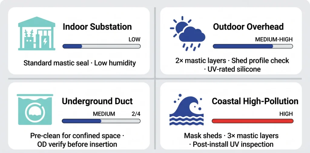
Categoria de erro 4 - Erros ambientais e de vedação
Uma terminação de encolhimento a frio com geometria de interface interna correta ainda pode falhar em seus limites externos. A entrada de umidade através da vedação do revestimento pode levar de dois a quatro anos de ciclos térmicos antes que a frente condutora atinja o isolamento do cabo e a falha resultante seja indistinguível de um defeito de interface no estágio de instalação.
Erros de sequência de aplicação de mástique de vedação
O mastique é a principal barreira contra umidade na junção entre o corpo e a jaqueta de encolhimento a frio. Os dois erros mais comuns são a inversão da sequência de aplicação do mastique após o posicionamento do acessório, e não na superfície da jaqueta, e o estiramento excessivo da fita abaixo de 70-80% de sua espessura relaxada. Em jaquetas de cabos perfiladas, é necessário um mínimo de duas camadas com meia camada para preencher os vazios da superfície.
Contaminação por umidade durante a instalação de intervalo aberto
Seis terminações externas instaladas durante um evento de neblina marítima costeira mostraram padrões de rastreamento de umidade em quatro das seis, 14 meses após a energização; todas as seis passaram no hi-pot de 10 kV CC no comissionamento. As duas terminações não afetadas foram instaladas depois que a neblina passou. Suspenda a instalação quando a umidade relativa exceder 80% ou quando houver condensação visível em qualquer superfície de cabo ou acessório.
Contaminação em ambientes costeiros ou de alta poluição
O silicone tem excelente resistência inerente ao rastreamento e à erosão, mas somente se a superfície externa chegar sem danos e limpa ao serviço externo. O transbordamento de mástique em superfícies de galpão ou danos físicos durante a instalação em espaços confinados reduzem a distância de fuga efetiva - o comprimento do caminho ao longo da superfície do isolador que resiste ao rastreamento da superfície sob contaminação úmida - sem qualquer indicador visual pós-instalação. Os requisitos de classificação da gravidade da poluição para isolamento externo são abordados emIEC 60815.
Fig.-04: Matriz de zonas de risco ambiental para terminação de cabos e instalação de juntas por encolhimento a frio, classificando os requisitos de vedação e os níveis de exposição à contaminação em subestações internas, subestações externas, dutos subterrâneos e ambientes costeiros de alta poluição.
[Expert Insight] - Controles ambientais de instalação
Limite de umidade: suspenda a preparação do cabo em intervalo aberto acima de 80% RH no local da instalação
Mínimo de mástique: duas camadas de meia volta em superfícies de jaqueta perfilada; três em perfis corrugados
Proteção da superfície do galpão: cubra os perfis do galpão com uma folha de polietileno limpa durante a aplicação do mastique para evitar a contaminação por transbordamento
Inspeção de aprovação/reprovação antes da energização
A inspeção estruturada de pré-energização captura o subconjunto detectável de erros de instalação e cria uma linha de base dimensional verificada para qualquer investigação de falha futura.
Pontos de controle visuais e dimensionais
Ponto de controle
Critérios de aprovação
Indicador de falha comum
Qualidade do corte semicondutor
Cone suave de 20 a 35 mm; sem degrau na ponta do dedo
Borda afiada; resíduo de carbono no limite do cone
Condição da superfície do isolamento
Limpo, seco, sem contaminação sob iluminação angular
Faixas de poeira de carbono; brilho de solvente; filme de condensação
Posição axial do acessório
Marca de referência no local correto em relação ao corte semicondutor
Marca ausente; acessório deslocado >5 mm
Confirmação da remoção do núcleo
Espiral totalmente removida; nenhum fragmento dentro do corpo do acessório
Segmento central visível; zona de retração parcial presente
Superfície externa de silicone
Sem cortes, perfurações ou danos ao galpão; sem mástique nos perfis do galpão
Marcas de contato de ferramentas; galpões contaminados com mástique
Integridade da vedação de mástique
Mínimo de duas camadas com meia sobreposição; sem lacunas na borda da sobreposição
Camada única com a superfície da jaqueta visível através do mastique
Antes de aplicar o acessório, verifique e registre três dimensões em relação à folha de dados do kit: diâmetro externo do isolamento do cabo em três posições axiais com um paquímetro calibrado, comprimento de corte do semicondutor e comprimento de exposição do condutor. Essas medições levam menos de quatro minutos e formam a linha de base da rastreabilidade dimensional para a vida útil do acessório.
Testes elétricos de pré-energização
A resistência do isolamento a 2,5-5 kV CC por 60 segundos (mínimo >1.000 MΩ) examina falhas graves, contaminação por umidade, rastreamento de superfície e exposição não intencional do condutor. Quando o teste de descarga parcial estiver disponível como padrão crescente em projetos de classe de 35 kV, um resultado que não mostre atividade mensurável acima de 10-20 pC a 1,0-1,5 vezes a tensão operacional é o critério de aprovação de pré-energização de maior confiança disponível no campo. Qualquer falha em um único ponto de controle é motivo para remoção e reinstalação do acessório, não para correção no local.
Como selecionar o kit de encolhimento a frio correto para reduzir o risco de erros de instalação
Um kit corretamente combinado oferece ao instalador um sistema projetado para ser bem-sucedido. O Mapa de seleção completo para acessórios para cabos abrange o processo de especificação completo, esta seção isola os parâmetros mais diretamente ligados aos modos de falha acima.
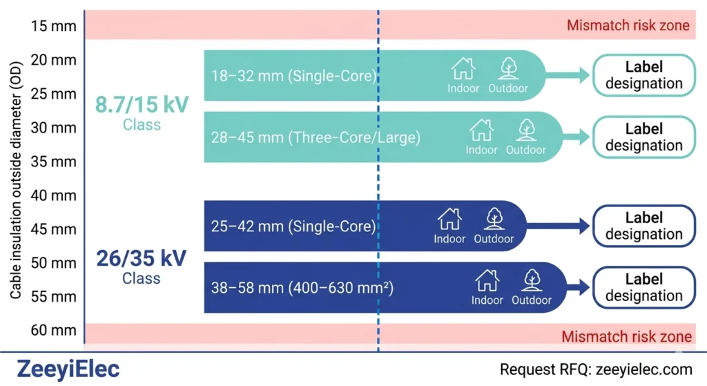
Faixa de OD do cabo e correspondência de classe de tensão
Classe de tensão
Faixa típica de OD de isolamento
Lógica de seleção de teclas
8,7/15 kV
18-32 mm (XLPE de núcleo único)
Selecione o kit cujo ponto médio do diâmetro externo esteja mais próximo do diâmetro externo do cabo medido
8,7/15 kV
28-45 mm (condutor de três núcleos ou grande)
Verificar o diâmetro externo por núcleo para juntas; diâmetro externo de núcleo individual para terminações
26/35 kV
25-42 mm (XLPE de núcleo único)
Faixa de tolerância mais estreita - a correspondência de OD de faixa média é mais crítica nessa classe
26/35 kV
38-58 mm (condutor de 400-630 mm²)
Confirme a espessura da parede do isolamento com base na folha de dados do cabo; parede de 9 a 12 mm típica dessa classe
Tipo de terminação, ambiente e compatibilidade de isolamento
As designações para ambientes internos e externos não são intercambiáveis: uma terminação com classificação para ambientes internos instalada em ambientes externos elimina a margem de distância de fuga exigida pela classe de tensão, independentemente da qualidade do procedimento de instalação. A compatibilidade do material de isolamento é igualmente importante: os acessórios de contração a frio testados para XLPE (constante dielétrica normalmente de 2,2 a 2,4) não são qualificados para o isolamento EPR (constante dielétrica normalmente de 2,8 a 3,5) sem verificação separada dos dados de qualificação do fabricante. Confirme ambos os parâmetros antes de finalizar o pedido de compra, e não após a entrega.
Os acessórios para cabos de contração a frio da ZeeyiElec abrangem as classes de 8,7/15 kV e 26/35 kV, com opções de terminação interna e externa e kits de junção direta projetados para tolerâncias dimensionais que reduzem a exposição a erros de ajuste em campo.
Fig. 05: Matriz de seleção do kit de contração a frio mapeando as faixas de diâmetro externo do isolamento do cabo para as faixas de classe de tensão (8,7/15 kV e 26/35 kV), com designações de terminação interna e externa para configurações de núcleo único e múltiplos núcleos.
Perguntas frequentes
Qual é o erro mais comum na instalação de encolhimento a frio?
O erro documentado com mais frequência é o preenchimento incorreto do semi-cone, cortando o quadrado da tela ou aplicando um cone muito curto, deixando um ponto de concentração de tensão dielétrica acentuado que o cone de tensão interno não consegue redistribuir; isso normalmente produz uma atividade de descarga parcial mensurável dentro de 12 a 36 meses, dependendo da classe de tensão e da frequência do ciclo de carga.
Quanto frio precisa estar para que a instalação de encolhimento a frio exija precauções especiais?
Os protocolos de pré-condicionamento são geralmente recomendados abaixo de 5 °C, pois a força de retração do silicone e a velocidade de recuperação são reduzidas em condições próximas a zero, aumentando o risco de vedação incompleta da interface, que passa no teste de alto ponto de comissionamento, mas inicia uma descarga parcial sob tensão de serviço contínua.
Um acessório de encolhimento a frio pode ser reposicionado depois que o núcleo em espiral for parcialmente removido?
O reposicionamento após o início da retração não é recomendado, pois o silicone já começou a se conformar na zona retraída e qualquer deslocamento axial desloca o cone de tensão interno de sua relação projetada com a borda de corte semicontraída, exigindo a remoção e a reinstalação completas do acessório.
Quanto tempo deve ser aguardado antes da energização após a instalação do encolhimento a frio?
Um período de estabilização de 15 a 30 minutos em temperaturas acima de 10 °C é amplamente observado para a recuperação de silicone e amálgama de mástique, estendendo-se para 45 a 60 minutos em condições de frio ou de alta umidade, embora o critério principal deva ser sempre a instrução de instalação do fabricante do kit específico, pois as formulações de silicone variam entre as famílias de produtos.
A contaminação da superfície do cabo sempre causa falha imediata?
A contaminação na interface silicone-isolamento raramente causa falhas imediatas; a maioria das instalações contaminadas passa nos testes padrão de comissionamento hi-pot, mas a camada cria locais de iniciação de descarga parcial que degradam a interface progressivamente, com falhas que normalmente aparecem de 6 a 24 meses após a energização e que frequentemente são atribuídas erroneamente a defeitos de material.
Qual é a velocidade correta de remoção do núcleo espiralado para acessórios de encolhimento a frio?
Uma rotação completa da espiral a cada 2 a 3 segundos é a prática padrão para acessórios de contração a frio de média tensão, permitindo que a frente de retração avance uniformemente e atinja o contato total da interface antes que a próxima seção seja liberada, com terminações de classe de 35 kV que exigem de 60 a 90 segundos para a sequência completa.
Os acessórios de contração a frio apresentam falhas diferentes em ambientes externos e subterrâneos?
Sim, as falhas externas se originam mais comumente na vedação contra intempéries e no perfil do galpão sob exposição aos raios UV e condições de poluição úmida, enquanto as falhas subterrâneas e no compartimento do painel de distribuição se originam mais comumente na interface interna entre o silicone e o isolamento, devido à contaminação ou à incompatibilidade dimensional introduzida durante a instalação em ambientes confinados.
yoyo shi
Yoyo Shi escreve para a ZeeyiElec, com foco em acessórios de média tensão, componentes de transformadores e soluções de acessórios para cabos. Seus artigos abrangem aplicações de produtos, fundamentos técnicos e percepções de sourcing para compradores do setor elétrico global.