ما المقصود بالتحكم في الإجهاد في عملية التوصيل بالانكماش البارد؟
تعمل نهاية الكابل القابلة للانكماش البارد على استعادة سلامة العزل في النقطة التي ينتهي عندها كابل الطاقة، لكن المشكلة الهندسية الأكثر تعقيدًا تكمن في الطبقة التي تليها مباشرةً: وهي إدارة المجال الكهربائي الذي ينشأ عند انتهاء الدرع العازل للكابل.
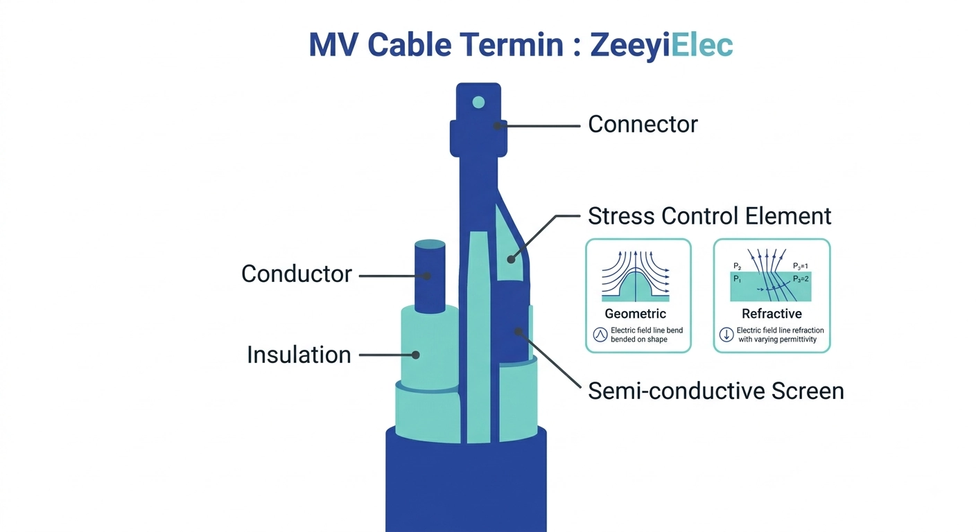
التحكم في الإجهاد هو طبقة التصميم — سواء كانت هندسية أو سعوية أو مزيجًا من الاثنين — التي تتولى إدارة هذا المجال بحيث يظل ضمن الحدود العازلة للمواد المحيطة، بدلاً من أن يتركز في نقطة واحدة إلى درجة اختراق العازل أو إحداث تيار سطحي.
في كابل الجهد المتوسط المبثوق في المصنع، تعمل ثلاث طبقات معًا: الموصل، والعزل الأساسي (عادةً ما يكون من مادة XLPE أو EPR)، ودرع عازل شبه موصل ملتصق فوق العزل ومربوط بالأرض. يحافظ هذا الدرع على التناظر الشعاعي للمجال الكهربائي حول الموصل، بنفس الطريقة التي يحافظ بها الكبل المحوري على مجاله بين الموصلين الداخلي والخارجي. ويظل المجال متجانسًا طالما ظل الدرع متصلاً دون انقطاع.
نقطة التخفيض باعتبارها انقطاعًا هندسيًّا
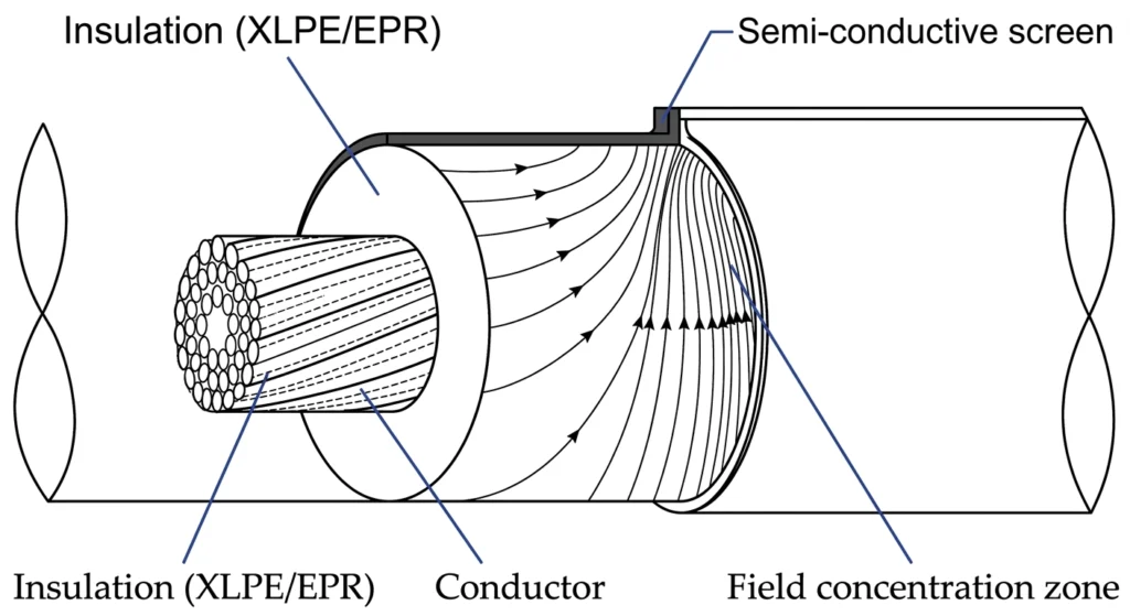
يتطلب التوصيل إزالة ذلك الغلاف العازل على طول معين لكشف العزل المكشوف من أجل الموصل. وفي اللحظة التي يتم فيها قطع الغلاف العازل، ينكسر تناسق المجال الكهربائي. وعند حافة القطع بالضبط، تتكدس خطوط المجال التي كانت تنتشر سابقًا بشكل متساوٍ حول الموصل في حجم أصغر بكثير من العزل — لتصبح نقطة تركيز إجهاد بدلاً من نقطة يتم فيها التحكم في الإجهاد. في الكابلات من فئة 15 كيلو فولت، يمكن أن يتجاوز تركيز المجال غير المُدار عند هذه الحافة قدرة العزل على التحمل المستمر بهامش كبير، وهذا هو السبب في أن كل تصميم للطرف — سواء كان الانكماش البارد أو الانكماش الحراري أو التوصيل بالضغط — يضم عنصرًا للتحكم في الإجهاد مباشرةً فوق نقطة القطع هذه بدلاً من التعامل معها على أنها مجرد انتقال ميكانيكي عاري.
دور التحكم في الضغط جنبًا إلى جنب مع العزل والإحكام
يُعد التحكم في الإجهاد وظيفة متميزة عن الوظيفتين اللتين يُوصف عادةً أن يقوم بهما طرف التوصيل — العزل والإحكام. فقد يتمكن طرف التوصيل من منع دخول الرطوبة بشكل مثالي، ومع ذلك يتعرض للفشل الكهربائي خلال السنة الأولى من استخدامه إذا كانت الهندسة الخاصة بالتحكم في الإجهاد عند نقطة القطع غير مناسبة لسمك عازل الكابل أو فئة الجهد. ولهذا السبب يتم تحديد مجموعات الانكماش البارد حسب فئة الجهد (عادةً في نطاقات 8.7/15 كيلو فولت أو 26/35 كيلو فولت) وحسب نطاق قطر الموصل/العزل، وليس كغلاف عالمي واحد — حيث يجب أن تتوافق الشكل الهندسي المصبوب في المجموعة مع الظروف الميدانية التي صُممت للتعامل معها.
رؤى الخبراء
قد يتعرض الوصلة التي تُغلق بإحكام تام للفشل من الناحية الكهربائية — فالإغلاق المحكم والتحكم في الإجهاد يعالجان مشكلتين مختلفتين.
فئة الجهد المذكورة على ملصق المجموعة ليست مجرد إجراء شكلي؛ بل إنها ترتبط ارتباطًا مباشرًا بالهيكل الهندسي للتحكم في الإجهاد المصبوب داخلها.
لا تستبدل أبدًا مجموعة مخصصة لفئة جهد معينة “لمجرد أن القطر مناسب” — فمطابقة القطر لا تعني بالضرورة ملاءمة التصنيف الميداني.
فيزياء الإجهاد الكهربائي عند نقطة قطع الكابل
مقطع عرضي يوضح تركيز المجال الكهربائي عند نقطة قطع غير مُدارة في الغطاء شبه الموصّل لكابل متوسط الجهد.
عند حافة الشاشة شبه الموصلة، لا يعود المجال الكهربائي موزعًا بشكل شعاعي — بل يصبح عرضيًا وغير متجانس إلى حد كبير، ويصل إلى ذروته بشكل حاد عند النقطة التي تنتهي عندها الشاشة بالضبط. وهذه نتيجة هندسية لإزالة سطح موصل مؤرض من المكان المجاور مباشرةً لنظام عازل لا يزال يحمل الجهد الكامل بين الطور والأرض. لا يضعف المجال تدريجيًا مع الابتعاد عن الموصل كما يحدث تحت شاشة سليمة؛ بل يرتفع محليًّا عند نقطة الانقطاع، وغالبًا ما يصل إلى عدة أضعاف شدة المجال الموجودة تحت عزل الكابل غير المتأثر على مسافة قصيرة.
لماذا تؤدي نقطة القطع غير المُدارة إلى حدوث تفريغ جزئي؟
التفريغ الجزئي — وهو انهيار كهربائي صغير ومحدود لا يكسر العزل بالكامل، لكنه مع ذلك يؤدي إلى تآكل المادة مع كل حدوث — يبدأ بمجرد أن تتجاوز شدة المجال المحلية عند حافة الشاشة عتبة بدء التفريغ الخاصة بالعزل المحيط أو السطح الفاصل بين الهواء والعزل. في كابل توزيع نموذجي من فئة 15 كيلو فولت يعمل بجهد نظام عادي، يمكن أن تؤدي نقطة القطع غير المُدارة إلى دفع شدة المجال الموضعية إلى نطاق تبدأ فيه نشاطات التفريغ الجزئي عند مستويات لن تحدث أبدًا تحت الجزء السليم والمحمي من الكابل — وهذا هو السبب الأساسي في أن التحكم في الإجهاد ليس اختياريًا في فئات الجهد المتوسط. يؤدي كل حدث تفريغ إلى تآكل كمية مجهرية من المادة، ويتطور التكرار المتواصل على مدى أشهر أو سنوات إلى شجرة كهربائية تربط في النهاية سماكة كافية من العزل لتسبب حدوث قفزة كهربائية.
لماذا يزداد أهمية هذا الأمر مع ارتفاع فئة الجهد الكهربائي
العلاقة بين فئة الجهد وأداء التحكم في الإجهاد المطلوب ليست خطية. فالوصلة الطرفية في نظام بجهد 35 كيلو فولت لا تحتاج فقط إلى “درجة أعلى” من تلك الموجودة في نظام بجهد 8.7 كيلو فولت — بل يجب تصميم الشكل الهندسي والسعة الكهربائية للعنصر خصيصًا لهذا المجال التشغيلي الأعلى، نظرًا لأن الفارق بين الجهد العادي للنظام وجهد بدء التفريغ يضيق مع ارتفاع فئة الجهد. وهذا هو الأساس الفيزيائي الذي يفسر سبب بيع مجموعات الانكماش البارد كمنتجات مخصصة لفئات الجهد المحددة: فالشكل الهندسي الذي يدير تركيز المجال بشكل ملائم عند 8.7/15 كيلوفولت سيكون أصغر من اللازم لتطبيق يعمل بجهد 26/35 كيلوفولت.
طرق التحكم في الإجهاد الهندسية مقابل طرق التحكم في الإجهاد الانكساري (السعوي)
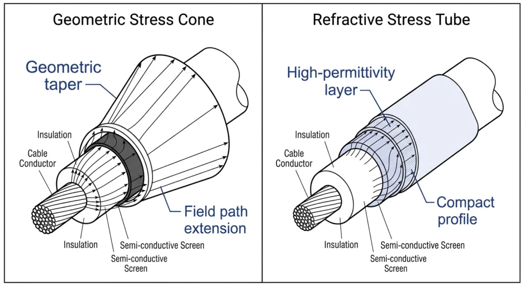
مقارنة مقطعية جنبًا إلى جنب بين الشكل الهندسي المخروطي المتناقص لمخروط الإجهاد والطبقات الانكسارية لأنبوب الإجهاد ذي السماحية العالية.
هناك نهجان هندسيان لحل نفس مشكلة تركز المجال عند نقطة قطع الكابل، وتستخدم معظم الوصلات القابلة للانكماش البارد أحد هذين النهجين أو مزيجاً منهما، اعتماداً على فئة الجهد وتصميم الوصلة.
الأقماع الهندسية للإجهاد: انتشار المجال الميكانيكي
يعمل مخروط الإجهاد الهندسي من خلال توسيع المسافة الانتقالية الفعالة ماديًّا بين الشاشة المؤرضة والعزل المكشوف. وبدلاً من القطع الحاد، يخلق الشكل المقولب للمخروط حدودًا موصلة تتسع تدريجيًّا، مما يؤدي إلى توزيع المجال على مسار مادي أطول، وبالتالي خفض شدة ذروة المجال عند أي نقطة فردية. يعتمد هذا النهج على الشكل بحتًا — ولا تتطلب أي خصائص عازلة خاصة بخلاف المطاط الصناعي الأساسي (عادةً مطاط السيليكون أو EPDM) المستخدم بالفعل في الجسم القابل للانكماش البارد. ويُعد التحكم الهندسي أمرًا شائعًا في الوصلات من فئة 8.7/15 كيلو فولت حيث تظل مسافة انتشار المجال المطلوبة ضمن طول مخروطي عملي.
أما التحكم في الإجهاد الانكساري، أو السعوي، فيعتمد بدلاً من ذلك على مركب تتميز ثابتة السعة الكهربائية فيه بقيمة أعلى بكثير من عازل الكابل المحيط — وغالبًا ما تقع ثابتة السعة النسبية لهذا المركب في نطاق يزيد عدة مرات عن ثابتة السعة النسبية للبولي إيثيلين الموسع (XLPE). ويؤدي هذا التباين في السماحية إلى إعادة توزيع المجال كهربائيًا وليس ميكانيكيًا: حيث تجذب المادة ذات السماحية العالية خطوط المجال إلى داخلها وتطلقها بشكل تدريجي على طولها، مما يؤدي إلى تسطيح الذروة التي كانت ستتشكل لولا ذلك عند حافة الشاشة. تتيح هذه الطريقة الحصول على مقطع طرفي أكثر إحكامًا، وهو أمر مهم مع ارتفاع فئة الجهد وصعوبة توفير المساحة المادية اللازمة لاستيعاب التناقص الهندسي الطويل.
إرشادات فئة الجهد بشأن الطريقة التي ينبغي تطبيقها
المعلمة
مخروط الإجهاد الهندسي
انكساري (سعوي)
فئة الجهد النموذجية
8.7/15 كيلو فولت
15 كيلوفولت – 35 كيلوفولت وما فوق
الآلية
إطالة المسار المادي
السعة الكهربائية (εr) تصنيف حالات عدم التطابق
ملف تعريف الإنهاء
طول مدبب أطول
طول محوري أكثر إحكاما
الحساسية تجاه أخطاء التثبيت
معتدل — تفاوت موضع المخروط
أعلى — يُعد وضع المركب والتلامس الخالي من الفراغات أمرًا بالغ الأهمية
في الممارسة الميدانية، تجمع بعض مجموعات 26/35 كيلو فولت بين الآليتين — تدرج هندسي أقصر مقترن بطبقة انكسارية — للحفاظ على الطول الإجمالي للنهاية ضمن نطاق عملي مع الاستمرار في تلبية متطلبات الأداء المتدرج ميدانيًا التي تتطلبها فئة الجهد الأعلى. ولا تعتبر أي من الطريقتين متفوقة بطبيعتها؛ فالاختيار الصحيح يعتمد على سماكة عازل الكابل، ومساحة التركيب المتاحة، والتصميم المعتمد من قبل الشركة المصنعة للمجموعة لفئة الجهد المحددة تلك، بدلاً من الاعتماد على قاعدة عامة.
ماذا يحدث عندما تفشل السيطرة على التوتر أو تُطبق بشكل خاطئ
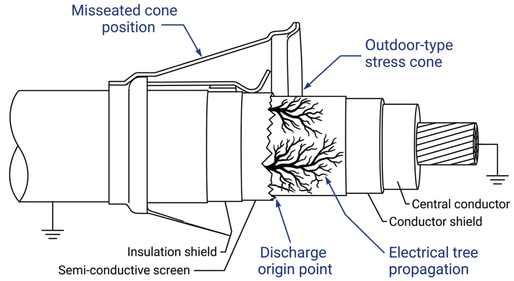
تشعب كهربائي متفاقم ينشأ من موضع مخروط إجهاد غير مثبت بشكل صحيح، ويمتد مع مرور الوقت من حافة الشاشة باتجاه الموصل.
نادرًا ما تظهر أعطال أنظمة التحكم في الإجهاد عند بدء التشغيل. فعادةً ما يجتاز الوصلة التي تحتوي على مخروط غير مثبت بشكل صحيح أو طبقة انكسارية غير ملتصقة بالكامل اختبارات الجهد العالي الأولية أو اختبارات مقاومة العزل دون أي مشكلة، لأن العيب يمثل تركيزًا موضعيًّا للمجال الكهربائي، وليس مشكلة في العزل الكلي — والاختبارات التي تركز على العزل الكلي ليست دائمًا حساسة بما يكفي لاكتشافه. يتطور العطل لاحقًا، تحت جهد التشغيل العادي، على مدى فترة زمنية قد تمتد من بضعة أشهر إلى عدة سنوات، اعتمادًا على مدى ابتعاد التركيب عن الشكل الهندسي الصحيح.
حالة ميدانية: تحديد موضع مخروط الإجهاد المنزوح
في إحدى الحالات المتكررة في الميدان، يتعطل وصلة التوصيل القابلة للانكماش البارد ذات الجهد 15 كيلو فولت قبل انتهاء عمرها التشغيلي المتوقع بفترة طويلة — أحيانًا خلال الأشهر الـ 12 إلى 18 الأولى — ويُظهر الفحص الذي يُجرى بعد التعطل أن سبب المشكلة يعود إلى مخروط الضغط الذي تم تثبيته على بعد بضعة ملليمترات من موضعه المحدد فوق فتحة الشاشة. ويؤدي هذا الخطأ البسيط في تحديد الموضع إلى ترك شريحة صغيرة من حافة الغطاء خارج منطقة تدرج المجال الخاصة بالمخروط، مما يعيد تكوين نقطة التركيز الدقيقة التي صُمم المخروط للقضاء عليها. وتعد علامة الفشل — وهي مسار تآكل متفحم ينشأ من نقطة محددة بدلاً من تدهور العزل المنتشر — مؤشراً تشخيصياً قوياً على أن هندسة التحكم في الإجهاد، وليس عزل الكابل السائب، هي السبب الجذري.
مسار الفشل التدريجي
يمر المسار من عنصر التحكم في الإجهاد المطبق بشكل خاطئ إلى الفشل الكامل عمومًا بثلاث مراحل. أولاً، يبدأ نشاط التفريغ الجزئي عند نقطة التركيز غير الخاضعة للرقابة، وغالبًا عند مستويات جهد لا يصل إليها التفريغ في أي مكان آخر على كابل موصّل بشكل صحيح. ثانياً، تؤدي كل دورة تفريغ إلى تفحيم كمية مجهرية من مادة العزل، مما يؤدي إلى امتداد مسار تتبع مرئي — يُعرف عادةً باسم «التشعب الكهربائي» — إلى عمق أكبر داخل سماكة العزل. ثالثًا، بمجرد أن تربط الشجرة جزءًا كافيًا من مسار العزل المتبقي، تؤدي القدرة المتناقصة على التحمل إلى حدوث قفزة كهربائية، وعادةً ما يحدث ذلك أثناء تغير مؤقت في الجهد مثل التبديل أو موجة صاعقة ناتجة عن البرق، وليس تحت الحمل في حالة الاستقرار.
لماذا تظل الأعراض خفية حتى مرحلة متأخرة؟
ونظرًا لأن التفريغ الجزئي على هذا النطاق لا ينتج عنه أي علامة خارجية مرئية، بل يسبب فقط تغيرًا هامشيًا يصعب اكتشافه في تيار التسرب، فإن فرق العمل الميدانية ومالكي الأصول لا يتلقون عادةً أي تحذير قبل حدوث العطل، ما لم يكن الموقع مزودًا بنظام مراقبة مستمر للتفريغ الجزئي — وهو أمر غير شائع في أصول شبكة التوزيع خارج المحطات الفرعية الكبيرة. وهذا هو الحجة العملية لضرورة ضبط مواقع التحكم في الإجهاد بشكل صحيح عند التركيب بدلاً من الاعتماد على الكشف في المراحل اللاحقة.
حقائق التركيب الميداني: التثبيت والتحقق من التحكم في الإجهاد
لا يعمل نظام التحكم في إجهاد الانكماش البارد بالشكل المقصود تمامًا إلا عندما تتطابق الشكل الهندسي المركب مع ما أقره المصنع خلال اختبار النوع — مما يجعل أبعاد تجهيز الكابل وموضع المخروط هما المتغيران اللذان يحددان بشكل مباشر ما إذا كان الوصلة النهائية ستصمد طوال عمرها التشغيلي المقصود الذي يتراوح بين 20 و30 عامًا.
تفاوتات إعداد الكابل التي تؤثر على موضع المخروط
تحدد كل مجموعة من مجموعات الانكماش البارد ورقة أبعاد خاصة بإعداد الكابل: المسافة التي يجب نزع الغلاف الخارجي عنها، ومكان قطع الغطاء شبه الموصّل، ومدى شطف أو تدرج حافة القطع تلك. هذه الأبعاد ليست عشوائية — حيث يتم تشكيل مخروط الضغط أو الأنبوب الانكساري بحيث يستقر على مسافة محددة من قطع الشاشة، ويمكن لأي خطأ في التحضير، حتى لو كان 5–10 مم، أن يزيح المخروط عن موضعه المصمم بالنسبة لنقطة التركيز الميدانية التي من المفترض أن يديرها. في الممارسة الميدانية، يتمثل الخطأ الأكثر شيوعًا في التحضير في قطع الشاشة على مسافة قريبة جدًا من الموصل، مما يترك عزلًا مكشوفًا غير كافٍ لترسيخ المخروط بشكل صحيح ويجبر المُركِّبين على التعويض بطرق لم تُصمم المجموعة لاستيعابها.
الفحوصات البصرية والقياسية قبل إزالة اللب
قبل فك اللفات عن اللب القابل للإزالة والسماح لجسم السيليكون بالانهيار على الكابل، يتحقق المُركِّبون من موضع المخروط مقارنةً بالخطوط المرجعية التي حددتها الشركة المصنعة — حيث تُطبع معظم مجموعات الانكماش البارد علامات المحاذاة مباشرةً على الجزء المُعد من الكابل أو توفر أداة تمييز منفصلة لهذا الغرض. ويمكن تصحيح وضع المخروط الذي يقع حتى لو كان قليلاً إلى الأمام أو الخلف من علامته المرجعية في هذه المرحلة؛ أما بمجرد إزالة اللب وانهيار الجسم بفعل ذاكرته المرنة، فإن إعادة وضعه لا تكون ممكنة عمومًا دون قطع المجموعة والبدء من جديد باستخدام مجموعة أخرى.
الأخطاء الشائعة على مستوى طاقم العمل وكيفية اكتشافها في مرحلة مراقبة الجودة
خطأ
العواقب
نقطة الكشف الخاصة بمراقبة الجودة
تم قطع الشاشة على مسافة قريبة جدًا من الموصل
المساحة غير كافية لترتيب المقاعد على شكل مخروط
فحص الأبعاد قبل التركيب
تمت إزالة القلب قبل التأكد من المحاذاة
المخروط مثبت في وضع خاطئ
الفحص البصري قبل تزويد الدائرة بالتيار الكهربائي
سطح العازل الملوث أو الذي عليه خدوش
منطقة تكوين الفراغ تحت التحكم في الإجهاد
فحص السطح أثناء مرحلة التحضير
تم اختيار فئة جهد غير صحيحة لمجموعة التجهيزات
هندسة تصنيف الميدان ذات الأبعاد الأصغر من المعيار
التحقق المتبادل بين البيانات المذكورة على اللوحة التعريفية ومحتويات المجموعة
رؤى الخبراء
علامات المحاذاة موجودة لسبب ما — تحقق من موضع المخروط مقارنةً بها قبل إزالة اللب، وليس بعد ذلك.
بمجرد انهيار الهيكل المصنوع من السيليكون، يصبح من المستحيل إعادة ضبط موضعه؛ والحل الوحيد هو استخدام مجموعة قطع غيار جديدة.
تُظهر الفرق التي لا تعرف قواعد وضع العلامات الخاصة بعلامة تجارية معينة نسبة غير متناسبة من أخطاء تحديد المواقع — فالإلمام بالعلامة التجارية لا يقل أهمية عن المهارة العامة.
المراجع المتعلقة بالمعايير والجهات المختصة لتصميم أنظمة التحكم في الإجهاد
لا يتم التحقق من صحة تصميم التحكم في إجهاد الانكماش البارد من خلال الخبرة الميدانية وحدها — حيث تثبت الشركات المصنعة للمجموعات أداء منتجاتها وفقًا لبروتوكولات اختبار النوع المعترف بها دوليًا قبل طرح مجموعة المنتجات للاستخدام في شبكات الجهد المتوسط، وينبغي على فرق المشتريات المسؤولة عن شراء الوصلات أن تطلب الاطلاع على هذه الوثائق بدلاً من الاكتفاء بقبول ادعاءات الخدمة الميدانية دون تدقيق.
إطار المعايير الذي ينظم أداء إنهاء الخدمة
تنظم المواصفة القياسية IEC 60502-4 طرق الاختبار ومتطلباته الخاصة بالملحقات المستخدمة في كابلات الطاقة ذات التصنيف من 1 كيلوفولت إلى 30 كيلوفولت، وهي المعيار الأكثر شيوعًا في اختبارات أنواع التوصيلات القابلة للانكماش على البارد، حيث تغطي التفريغ الجزئي، ومقاومة النبضات، وأداء الدورات الحرارية للمجموعة المكتملة — بما في ذلك عنصر التحكم في الإجهاد — بدلاً من اختبار التحكم في الإجهاد بشكل منفصل. أما بالنسبة للوصلات التي تمتد إلى فئات الجهد الأعلى، فإن المعيار IEC 60840 يغطي الملحقات المستخدمة في الكابلات ذات الجهد المقنن الذي يتراوح بين 30 كيلوفولت و150 كيلوفولت، مع معايير قبول أكثر صرامة فيما يتعلق بالنبضات والتفريغ الجزئي.
ما الذي يتحقق منه اختبار النوع فعليًّا
لا يؤكد اختبار النوع أن كل وحدة إنتاج ستعمل بنفس الأداء — فهذا هو دور الاختبارات الروتينية التي تُجرى على 100% من المنتج قبل الشحن. بدلاً من ذلك، يتحقق اختبار النوع من صحة هندسة التحكم في الإجهاد نفسها: حيث تُخضع عينة من أطراف الكابل، مصنوعة وفقًا للأبعاد والمواد المحددة بدقة في الإنتاج، لقياس التفريغ الجزئي تحت جهد مرتفع (عادةً ما يكون 1.5–2.0 أضعاف الجهد المقنن لفحص التفريغ الجزئي)، يلي ذلك اختبار مقاومة النبضات عند مستويات تتوافق مع مستوى العزل الأساسي للكابل ضد النبضات (BIL). وقد أثبت التصميم الذي يجتاز هذه الاختبارات أن هندسته المصنفة حسب المجال تحافظ على نشاط التفريغ أقل من العتبة المطبقة حتى في ظل ظروف اختبار أكثر قسوة من جهد التشغيل العادي.
لماذا يهم هذا الأمر للمشترين، وليس للمهندسين فحسب
يمكن لفرق المشتريات التي تقوم بتقييم موردي الأنابيب الباردة القابلة للانكماش أن تطلب، بشكل معقول، شهادة اختبار النوع الخاصة بفئة الجهد المحددة وحجم الكابل المطلوب، حيث إن الشهادة الصادرة لفئة جهد معينة أو نطاق موصل معين لا تنطبق تلقائيًّا على فئة أو نطاق آخر — فالخصائص الهندسية ترتبط بفئة الجهد المحددة، كما تم توضيحه سابقًا في هذا الدليل. يمكن للمشترين الرجوع إلى معيار اختبار ملحقات الكابلات IEC 60502-4 بشكل مباشر فيما يتعلق بمتطلبات الاختبار المحددة التي يجب أن تثبتها شهادة المورد.
تواصل مع فريق الهندسة في ZeeyiElec بخصوص الوصلات القابلة للانكماش البارد
تعد هندسة التحكم في الإجهاد إحدى التفاصيل التي تميز الوصلة التي تعمل بشكل موثوق لأكثر من 20 عامًا عن تلك التي تتعطل خلال دورة الخدمة الأولى — وهي ليست أمرًا يمكن تركه لمجرد مطابقة عامة في الكتالوج. إذا كنت تحدد ملحقات الكابلات المتقلصة على البارد بالنسبة لمشروع توزيع قادم، يمكن للفريق الفني في ZeeyiElec التأكد من نوع التحكم في الإجهاد الصحيح ومقاس المجموعة المناسب وفقًا لسمك عازل الكابل وفئة الجهد الخاصين بك قبل أن تقرر تقديم الطلب.
بالنسبة للمشاريع التي لا تزال تدرس تقنية الإنهاء بشكل عام، فإن دليل اختيار ملحقات الكابلات يستعرض إطار العمل الكامل لاتخاذ القرار عبر فئات الجهد وبيئات التركيب المختلفة، ومقارنتنا بين تقنيات الانكماش البارد مقابل تقنيات الانكماش الحراري يتناول هذا المقال الاختلافات في الاعتبارات المتعلقة بالتحكم في التوتر بين الاثنين.
التوريد عبر نطاق كامل ملحقات المحولات أو ملحقات الكابلات حزمة لتركيب في مواقع متعددة؟ يرجى إطلاعنا على مواصفات الكابلات وفئة الجهد وظروف الموقع، وسنرد عليكم بتوصيات فنية إلى جانب عرض أسعار، مع توفير وثائق الاختبار عند الطلب لفئة الجهد المحددة التي تحتاجونها.
التحكم في الإجهاد هو الطبقة المصممة هندسيًّا — سواء كانت هندسية أو سعوية — التي تعمل على توزيع أو تدرج المجال الكهربائي المركّز عند النقطة التي يتم فيها قطع الغلاف العازل للكابل، مما يمنع حدوث انهيار عازل موضعي عند تلك الواجهة.
لماذا تشكل إزالة الشاشة شبه الموصلة مشكلة؟
يؤدي قطع الشاشة إلى حدوث انقطاع حاد بين الأسطح المؤرضة وغير المؤرضة، مما يؤدي إلى تركيز المجال الكهربائي عند تلك الحافة بمستوى يتجاوز بكثير إجهاد التشغيل العادي للكابل، لا سيما في أنظمة الجهد المتوسط من فئة 15 كيلوفولت إلى 35 كيلوفولت.
ما الفرق بين التحكم في الإجهاد الهندسي والتحكم في الإجهاد الانكساري؟
يستخدم التحكم الهندسي في الإجهاد مخروطًا مرنًا ذي شكل معين لتوزيع المجال فعليًّا على مسار أطول، بينما يستخدم التحكم الانكساري (السعوي) مركبًا عالي السماحية لإعادة توزيع المجال كهربائيًّا؛ ويعتمد الاختيار عمومًا على فئة الجهد ونوع التوصيل.
هل يمكن أن يعمل قاطع الدائرة دون التحكم في الإجهاد عند الجهد العالي؟
في الوصلات ذات الجهد المنخفض التي تصل إلى حوالي 1 كيلوفولت، لا تكون هناك حاجة عمومًا إلى التحكم في الإجهاد، ولكن في أنظمة الجهد المتوسط التي تتجاوز بضعة كيلوفولتات، يؤدي تجاهل ذلك عادةً إلى تسارع نشاط التفريغ الجزئي وإلى حدوث أعطال مبكرة.
كيف تتأكد فرق العمل الميدانية من أن جهاز التحكم في الضغط مثبت بشكل صحيح؟
عادةً ما تتأكد فرق العمل من موضع المخروط أو الأنبوب وفقًا لأبعاد إعداد الكابل المحددة من قبل الشركة المصنعة، وتقوم بفحص بصري للتأكد من وجود تلامس كامل وخالٍ من الفراغات على امتداد منطقة قطع الشبكة قبل إغلاق الوصلة.
ما هي علامات الإنذار المبكر التي تشير إلى فشل التحكم في التوتر؟
نادرًا ما تظهر العلامات المبكرة ظاهريًّا؛ فعادةً ما تظهر الأعطال في شكل تفريغ جزئي يمكن اكتشافه من خلال الاختبارات التشخيصية، أو في وقت لاحق في شكل آثار تيار كهربائي وتسخين موضعي يتم اكتشافهما أثناء الفحص الذي يُجرى بعد حدوث العطل.
هل يختلف تأثير الإجهاد على الأداء باختلاف أنواع عزل الكابلات؟
نعم — تتميز العوازل المصنوعة من البولي إيثيلين عالي الكثافة (XLPE) والبولي إيثيلين الممدد (EPR) بخصائص عازلة مختلفة، لذا فإن عنصر التحكم في الإجهاد الذي تم التحقق من صلاحيته لنوع معين من العوازل لا يكون مناسبًا تلقائيًّا للنوع الآخر ما لم تؤكد الشركة المصنعة توافق هذا المزيج المحدد.
يويو شي
تكتب يويو شي في ZeeyiElec، مع التركيز على ملحقات الجهد المتوسط ومكونات المحولات وحلول ملحقات الكابلات. تغطي مقالاتها تطبيقات المنتجات، والأساسيات التقنية، ورؤى المصادر للمشترين العالميين في مجال الصناعات الكهربائية.





 English
 한국어
한국어 العربية
 Español
 हिन्दी
 தமிழ்
தமிழ் Deutsch (Sie)
 Français
 Português do Brasil
 Русский