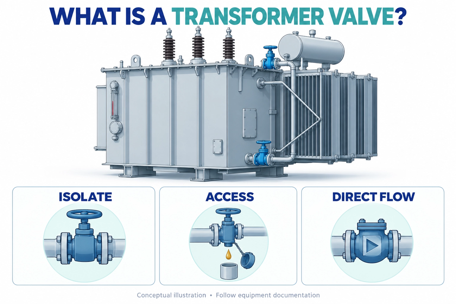
A transformer valve is a mechanical device that controls a designated liquid path in an oil-immersed transformer. Depending on its design and location, it can isolate a cooling branch, provide access for draining or sampling, or restrict reverse flow. Its function must be understood from the equipment drawing, not appearance alone.
This explanation is for engineers, maintenance planners, and buyers who need to understand what an installed valve does before discussing service or replacement. It explains functions and boundaries rather than prescribing valve positions, switching sequences, or a universal purchasing specification.
How a Transformer Valve Relates to the Oil System
Insulating liquid serves two connected purposes: it contributes to electrical insulation and transports heat from the active part toward cooling surfaces. A valve acts on a liquid passage; it does not interrupt the transformer’s electrical circuit. Closing an oil connection therefore does not establish electrical isolation.
The tank, connecting pipework, radiator or cooler, and service fittings form an arrangement defined by the transformer manufacturer. Some designs use natural circulation, while others include pumps. A valve’s significance depends on where it sits within that arrangement and which equipment lies on either side.
Location explains the duty
A connection between the tank and a removable radiator may include an isolation fitting. A low-level outlet may provide drainage access. A separate sampling fitting may allow oil to be collected under a prescribed procedure. Similar-looking bodies can serve different duties, and a combined drain-and-sample assembly can contain more than one controlled passage.
These components belong within the broader transformer accessory system. They support liquid management alongside electrical interfaces, monitoring, and protection, but their mechanical acceptance criteria are different from the dielectric ratings used for bushings or cable terminations.
Read the complete circuit
An equipment drawing should identify the branch, connection, and associated component. The operating or maintenance instruction then explains the permitted state for the task. Neither a photograph nor the fact that a handle turns easily can establish those requirements.
For example, a cooling branch that remains unintentionally isolated can lose its intended heat-transfer contribution. Whether that affects permissible loading depends on the equipment design and operating conditions; it cannot be calculated from the valve photograph alone.
Three Transformer Valve Functions That Should Not Be Confused
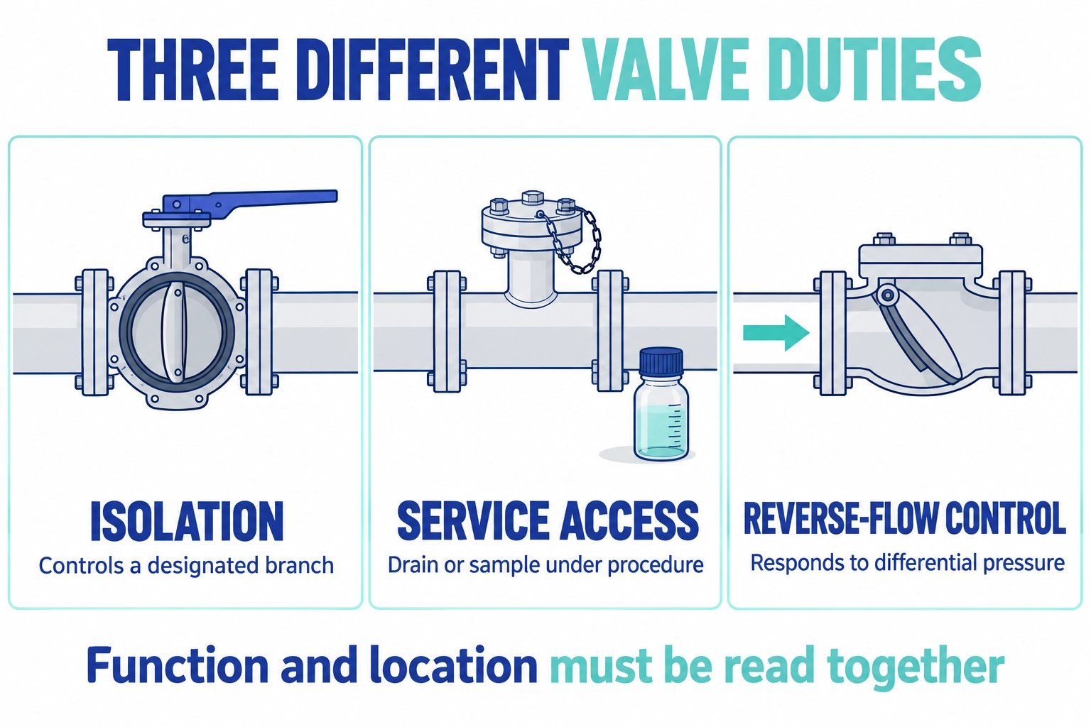
The term transformer valve describes an application, not a single internal mechanism. Isolation, service access, and reverse-flow control are different duties, even when two products share a nominal connection size.
Functional comparison
Duty
What the device controls
What its presence does not prove
Isolation
A designated liquid connection or branch
That the equipment is electrically isolated or the closed seat is leak-free
Drain or sampling access
An outlet used under the applicable service procedure
That the outlet is suitable for every sampling method or fluid-handling task
Reverse-flow control
Flow in the undesired direction under specified conditions
That a manually secured isolation boundary has been established
Butterfly mechanisms use a rotating disc, while ball mechanisms use a bored ball. Drain and sampling refer to purpose: the actual closure can use different constructions. A check valve normally responds to the pressure difference across its closure element rather than a manually selected handle position.
These definitions do not make the devices interchangeable. A one-way device needs the correct orientation and application conditions. A sampling assembly must suit the collection method. An isolation fitting needs the specified sealing performance for the intended work.
Conceptual valve sections distinguish branch isolation, controlled service access and reverse-flow control, showing why similar-looking fittings must be identified by their intended duty and circuit location.
For sampling work, IEC 60475:2022 addresses collection of insulating-liquid samples from electrical equipment, including transformers. Confirm which sampling procedure applies to the project before specifying the outlet arrangement.
A practical distinction
Suppose a drawing labels a fitting as a sampling connection but a buyer describes it only as a small ball valve. Ordering by that description could omit the outlet arrangement, protective cap, or connection needed by the sampling procedure. Identifying the function first prevents a visually plausible substitute from becoming the default choice.
[Expert Insight: An Illustrative Identification Review]
• A planner receives a close-up photograph without an equipment tag or location view.
• The useful next evidence is the drawing reference and a wider location photograph, not an assumed replacement model.
• This is a hypothetical review example, not a reported ZeeyiElec installation.
Why Sealing and Liquid Compatibility Matter
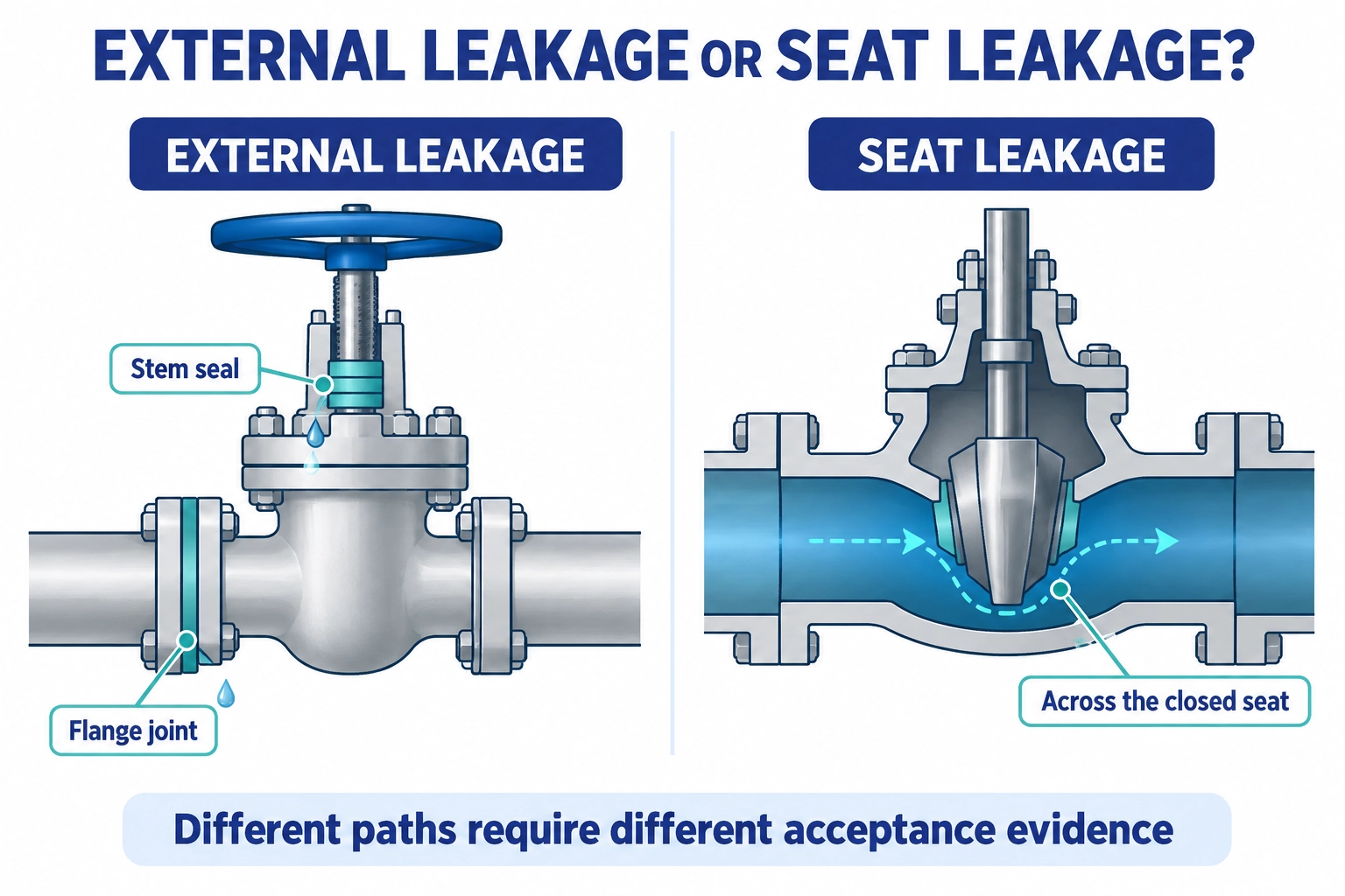
A transformer valve can have several distinct sealing interfaces. The body or cover contains the liquid; the stem seal limits leakage around the operating shaft; the flange gasket seals the connection; the seat controls passage across the closed element. A satisfactory result at one interface does not establish the others.
External leakage and seat leakage
Oil visible outside the assembly can originate at a stem, joint, or nearby component. Internal seat leakage instead passes through the closed valve into the connected passage. The outside may remain dry even when the closed seat allows some liquid through.
External sealing and closed-seat sealing serve different functions. A valve’s indicated closed position alone does not establish its leakage performance. Verify the applicable sealing design, test conditions and acceptance criteria in the documentation for the exact valve model.
Simplified leakage-path illustrations separate external stem or flange leakage from passage across a closed seat; clearances are exaggerated for explanation and are not manufacturing dimensions.
Compatibility involves the complete assembly
Insulating liquid, operating temperature, pressure duty, and exposure conditions affect the suitability of seals and wetted materials. An elastomer name alone is incomplete evidence: the selected compound, seal design, and manufacturer’s declared application all matter. Mineral oil approval should not silently become approval for an ester or another fluid.
Pressure and vacuum capability also require separate confirmation. A valve suitable for the normal liquid circuit is not automatically suitable for every processing or evacuation condition applied to the transformer. Obtain the specified duty from the work package and compare it with the exact component documentation.
This article intentionally gives no universal torque, pressure, leakage allowance, or test duration. Those values belong to the selected design and approved acceptance procedure, not to a generic definition of the component.
How to Interpret Transformer Valve Position and Condition
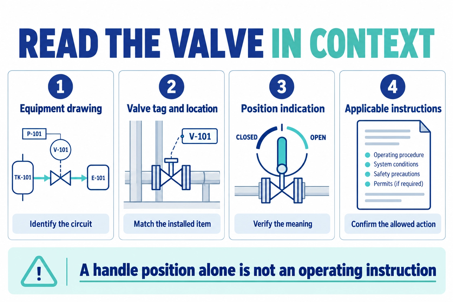
Understanding a transformer valve starts with identity, then location, indication, and instructions. A handle can be useful evidence, but its meaning depends on the mechanism and how the indicator is fitted. Do not assume every valve family shares the same travel, orientation, or position convention.
Position is not proof of readiness
A visible open or closed mark reports an indicated state. It does not independently prove correct internal engagement, acceptable seat leakage, or permission to operate the equipment. A missing or damaged indicator should be recorded as an uncertainty rather than replaced with a guess from a similar installation.
Likewise, a protective cap is part of an outlet arrangement, not evidence that every upstream closure has been verified. Consult the applicable instruction before disturbing caps, plugs, or connections. The liquid circuit may contain pressure, hot fluid, or conditions that are not apparent from its exterior.
The identification sequence links the equipment drawing, component location, position indication and applicable instructions; illustrative tags and symbols do not identify an actual installation or establish operating permission.
Record observations separately from conclusions
Useful observations include the equipment tag, valve marking, location, indicated position, visible external condition, and the time of inspection. Preserve a wider location view and a close-up of identifying features. Document what was seen without labelling every stain as active leakage or every discoloured seal as a confirmed failure.
[Expert Insight: An Illustrative Condition Report]
• A photograph shows oil staining below a flanged connection.
• The report should locate the stain and record the circumstances without declaring the flange gasket to be the proven source.
• The responsible team determines the inspection method and corrective action under the equipment procedure.
What a Transformer Valve Does Not Replace
An oil-system component should not be mistaken for electrical protection, a pressure-relief device, or an operating authorization. Those functions may sit near each other on the same tank, but physical proximity does not make their duties equivalent.
Keep liquid and electrical boundaries distinct
Valves do not substitute for isolation, grounding, absence-of-voltage verification, or the site’s other electrical safety controls. Any maintenance activity requires the responsible team’s approved work conditions. This article does not establish a safe sequence for opening a tank or operating a liquid circuit.
The distinction also helps at package interfaces. A project can involve both liquid-side fittings and cable connection accessories, yet the evidence needed to accept each is different. A valve inspection result cannot verify a cable connection, and an electrical test cannot establish every mechanical seal’s condition.
Keep definition separate from selection
Knowing the duty is the first step, not the completed specification. Nominal size does not define flange drilling, face-to-face length, gasket arrangement, allowable loading, or operator clearance. Two items can share a size designation while failing to fit the same assembly.
For the next decision stage, use the transformer accessory selection guide to place the fitting within the wider equipment specification. This definition page remains focused on understanding the installed function; product-specific selection requires the relevant valve drawings and acceptance requirements.
Describe the Transformer Valve Function Before Requesting Support
An enquiry about a transformer valve should link the component to its circuit, rather than relying on a cropped image and a guessed name. Include the transformer identification, valve tag or marking, relevant drawing, connection photographs, insulating liquid, and the purpose of the request.
A concise identification record
Information
Why it helps
Equipment and drawing reference
Locates the fitting within the correct assembly
Intended duty and branch
Separates isolation, service access, and reverse-flow control
Markings and photographs
Supports identification without assuming interchangeability
Fluid and operating conditions
Establishes which compatibility evidence is needed
Existing issue or proposed change
Distinguishes identification support from a repair decision
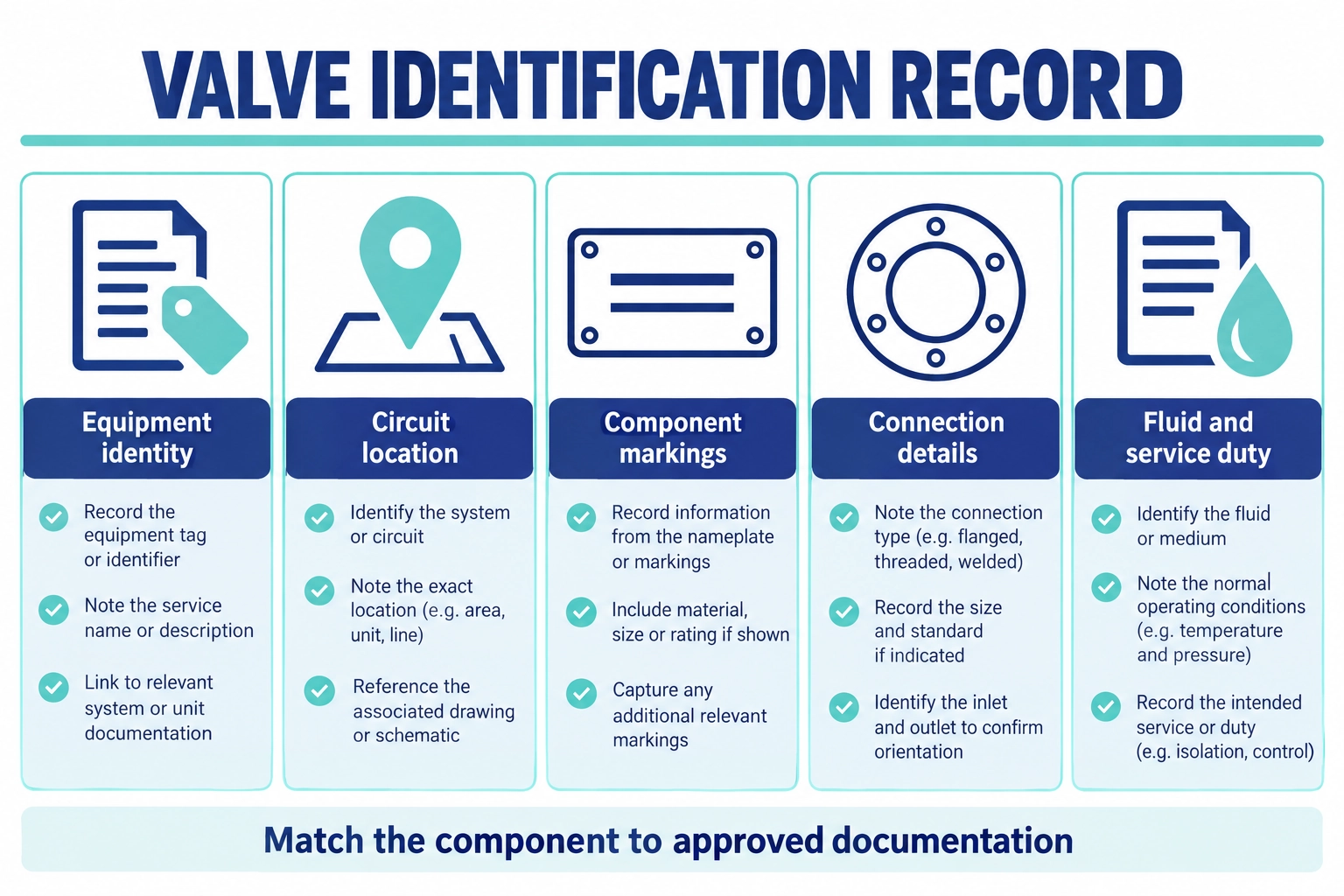
The identification record brings together equipment identity, circuit location, component markings, connection details and service conditions to support a documented technical enquiry without assuming interchangeability.
Use the ZeeyiElec valve product family as a starting point for discussing available configurations. Send the identification record to ZeeyiElec for a documentation and supply-scope review. The equipment manufacturer and responsible operator must still establish the accepted arrangement and any permitted service action.
Frequently Asked Questions
Is a transformer valve an electrical switching device?
No. It controls a liquid passage or service connection, so its position does not establish whether the electrical equipment is isolated or safe to work on.
Why can a transformer have several different valves?
Different locations can require cooling-branch isolation, drainage, sampling, or reverse-flow control. The equipment drawing identifies which duties are present in the particular design.
Does a closed valve always stop every leak?
No. External sealing and leakage across the closed seat are different questions, and acceptance depends on the specified design and applicable test criteria.
Are oil sampling and oil draining the same function?
No. Draining removes liquid for a service purpose, while sampling must support the specified collection method and sample quality; a combined fitting must be suitable for both intended tasks.
Can a check valve replace an isolation valve?
Do not assume so. A check device responds to differential pressure and flow direction, whereas an isolation arrangement must satisfy the equipment’s specified service boundary.
What information identifies an unknown transformer valve?
Start with the equipment tag, drawing location, component markings, connection details, and clear photographs. Those records support identification, but approved documentation must establish ratings and replacement suitability.
yoyo shi
Yoyo Shi writes for ZeeyiElec, focusing on medium-voltage accessories, transformer components, and cable accessory solutions. Her articles cover product applications, technical basics, and sourcing insights for global electrical industry buyers.





 English
 한국어
한국어 العربية
 Español
 हिन्दी
 தமிழ்
தமிழ் Deutsch (Sie)
 Français
 Português do Brasil
 Русский