This MV bushing installation torque control checklist walks through the sealing interface, torque staging, and diagnostic steps that determine whether a medium-voltage bushing holds up under thermal cycling and electrical stress over decades of service.
Torque control is not a formality in MV bushing installation — it’s the mechanism that determines whether the sealing interface holds under thermal cycling and electrical stress over decades of service. An under-torqued flange leaves microscopic gaps at the gasket interface, and an over-torqued one can crack porcelain housings or deform epoxy resin systems. Both shorten service life in ways that often don’t show up until months after commissioning.
Why Torque Control Matters in MV Bushing Installation
The bushing-to-turret interface relies on a gasket (typically nitrile or EPDM) achieving uniform compression across its full circumference. Insufficient compression — generally below the manufacturer’s minimum specified force — allows moisture ingress that accelerates partial discharge (PD) activity at the flange. In field commissioning work, technicians commonly find bushings that “look” seated but fail an insulation resistance test simply because one quadrant of the gasket never reached proper compression, a reminder that visual inspection alone isn’t a substitute for torque verification.
Gasket Compression and Sealing Interface
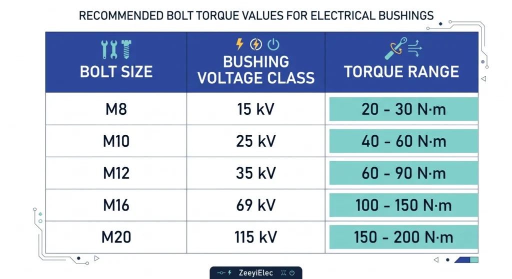
Typical flange bolt diameters for medium-voltage bushings range from 12 mm to 20 mm (M12–M20), with torque specifications generally falling between 40 N·m and 110 N·m depending on bolt grade and flange material. Always cross-reference against the OEM torque chart rather than applying a generic value.
Creepage/Clearance Preservation Under Mechanical Stress
Over-torquing can also distort the mounting flange, subtly reducing creepage distance between the bushing’s live end and grounded turret metal. This matters most for outdoor MV bushings rated 15 kV to 38 kV class, where creepage margins are already tight relative to contamination severity.
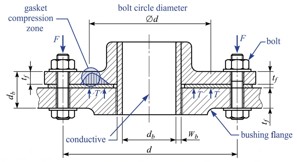
Flange stress distribution can be approximated where compression force F is roughly proportional to applied torque T, gasket friction coefficient μ, and bolt circle diameter d: F ≈ T / (μ × d). This relationship explains why bolt lubrication state changes achieved clamping force even at identical torque wrench readings.
Cross-sectional view of the bushing flange interface, showing how applied torque translates into gasket compression force across the bolt circle.
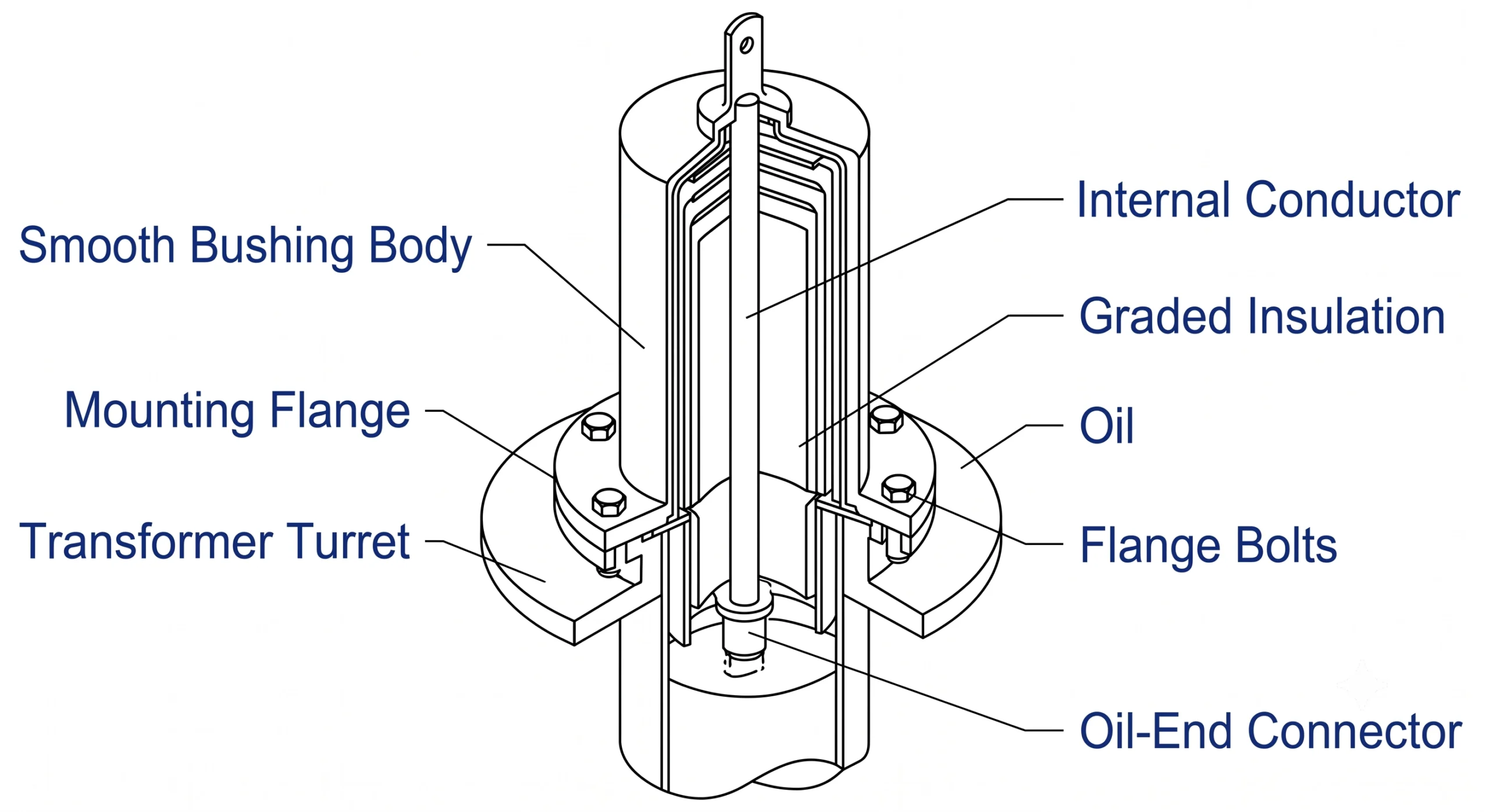
For broader context on bushing construction, see ZeeyiElec’s <a href=”https://zeeyielec.com/transformer-accessories/medium-voltage-bushings/”>medium-voltage bushings</a> series page.
Expert Insight
Visual seating never confirms torque — a gasket can look uniform and still be under-compressed in one quadrant
Bolt lubrication state alone can shift clamping force by 15-20% at the same torque reading
Creepage loss from flange distortion often isn’t visible until a PD test flags it
Pre-Installation Inspection Checklist
Before any torque wrench touches a bolt, the bushing, gasket, and mounting flange need a documented inspection pass. Skipping this step is one of the most common root causes traced back during troubleshooting calls — a scratched sealing surface or a gasket left in a damp crate overnight can undo an otherwise perfect torque sequence during MV bushing installation.
Bushing Surface and Porcelain/Epoxy Inspection
Inspect the full length of the bushing for hairline cracks, chips at the flange seat, or contamination film. Porcelain bushings should be checked under raking light for surface crazing; epoxy resin bushings need a check for chalking or UV degradation if they’ve been in outdoor storage. Reject any bushing with visible damage within 5 mm of the sealing groove — a small chip there is enough to compromise gasket seating.
Gasket and Mounting Flange Condition
Gaskets should be checked for compression set from prior storage stacking, and rejected if thickness has reduced by more than roughly 10-15% from nominal. Flange surfaces on the turret side should be checked for pitting, old gasket residue, or paint buildup exceeding 0.1 mm to 0.2 mm, since even thin coating layers change effective clamping height across the joint.
Contamination and Moisture Screening
In coastal or high-humidity sites, technicians commonly wipe both mating surfaces with isopropyl alcohol immediately before assembly, since residual moisture films have been linked to early-life PD activity during commissioning tests. Ambient humidity above roughly 85% RH is a common trigger for delaying installation, particularly for epoxy bushings where surface moisture can affect resin curing at touch-up areas.
Torque specifications for MV bushing flanges scale with bolt diameter, flange material, and gasket type — applying a “typical” value across bushing classes is a common source of field failures.
Bolt/Stud Material Grades
Most MV bushing flanges use stainless steel or zinc-plated carbon steel studs in grade 8.8 or A2-70 equivalents. Stainless studs generally require torque values roughly 10-15% lower than plated carbon steel at the same diameter, due to differences in thread friction coefficient — easy to overlook when reusing a torque chart across mixed hardware batches on a retrofit job.
Torque Range by Flange Diameter
The following reflects general industry practice; always confirm against the specific bushing manufacturer’s datasheet before applying in the field.
Bolt Size
Bushing Voltage Class
Typical Torque Range
M12
15 kV class
40 N·m – 55 N·m
M16
25 kV class
65 N·m – 85 N·m
M20
38 kV class
90 N·m – 110 N·m
These figures assume dry, unlubricated threads. If anti-seize compound is used, torque values are typically reduced by 15-20% to achieve equivalent clamping force, since lubrication lowers the friction coefficient referenced earlier. Field crews sometimes apply the same torque regardless of lubrication state, which can lead to gasket over-compression and, in porcelain bushings, hairline flange cracking that isn’t visible until a later maintenance inspection.
Reference table mapping bolt diameter and bushing voltage class to typical torque ranges for M12 through M20 mounting studs.For compatible switching hardware often installed alongside MV bushings, see ZeeyiElec’s loadbreak switch series page.
Step-by-Step Torque Application Sequence
Applying final torque in a single pass is one of the fastest ways to get uneven gasket compression, even when the target torque value is correct. The sequence and staging matter as much as the number on the wrench.
Star-Pattern Tightening Order
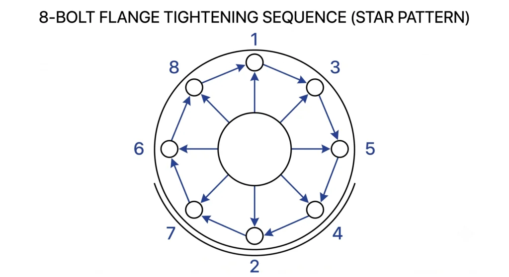
Bolts should be tightened in a star or cross pattern rather than sequentially around the flange circumference. For a typical 8-bolt MV bushing flange, this means tightening bolt 1, then the bolt roughly opposite (bolt 5), then 3, then 7, and so on — distributing compression evenly rather than progressively “walking” the gasket into an uneven seat. Skipping this pattern is a recurring finding during troubleshooting visits, particularly on retrofit jobs where crews work from memory rather than a documented procedure.
Staged Torque Passes (30% → 70% → 100%)
Final torque should be reached in at least three passes: an initial pass at roughly 30% of target to seat the gasket, a second pass at 70%, and a final pass at 100% — always following the same star pattern each time. A fourth “check pass” at full torque, performed after the joint settles for a few minutes, catches the relaxation that naturally occurs as the gasket compresses under load. For an M16 stud in the 65 N·m to 85 N·m range, this typically means passes at roughly 20 N·m, 55 N·m, and then final torque.
Ambient Temperature Considerations During Torquing
Cold ambient temperatures, particularly below 0°C, make gasket materials stiffer and less able to conform to minor flange irregularities, which can lead to under-sealing even at correct torque values. In these conditions, some crews perform a re-torque check once the transformer reaches normal operating temperature, since thermal expansion of the flange and gasket shifts the achieved clamping force slightly from the as-installed cold state.
Numbered star-pattern tightening sequence for an 8-bolt MV bushing flange, ensuring even gasket compression during staged torque passes.
Expert Insight
Never skip the 30/70/100 staging — single-pass torquing is the most common cause of uneven gasket seating
Cold-weather installs (<0°C) warrant a mandatory re-torque check once at operating temperature
A “check pass” after settling catches relaxation that single measurements miss
Common Installation Errors and Field Corrections
Most torque-related bushing failures trace back to one of a handful of recurring patterns, and recognizing the symptom early can prevent a minor installation error from becoming an in-service failure months later.
Over-Torque Failure Signs
Over-torquing most commonly shows up as hairline cracking at the porcelain flange seat or, in epoxy bushings, as stress whitening around the mounting holes. In one recurring field pattern, technicians using an impact wrench instead of a calibrated torque wrench for “speed” on multi-bushing installations have produced clamping forces 20-30% above target — often only apparent when the bushing fails a subsequent PD test rather than at the time of installation. Any bushing installed with an uncalibrated tool should be flagged for re-inspection.
Under-Torque and Partial Discharge Risk
Under-torqued flanges leave gaps that trap air or moisture at the gasket interface, becoming sites for partial discharge inception once the bushing is energized. A commissioning PD test showing low but non-zero activity at rated voltage on a new installation shouldn’t be treated as a pass by default — it often correlates with a torque shortfall on the final pass rather than a manufacturing defect, and is worth cross-checking against the project’s specified PD acceptance criteria before sign-off.
In both scenarios, the corrective action is the same: back off all bolts in reverse star pattern, inspect the gasket for visible damage or permanent set, replace if compression set exceeds the 10-15% threshold noted earlier, and re-run the full staged torque sequence rather than simply adding a bit more torque to an already-tightened joint.
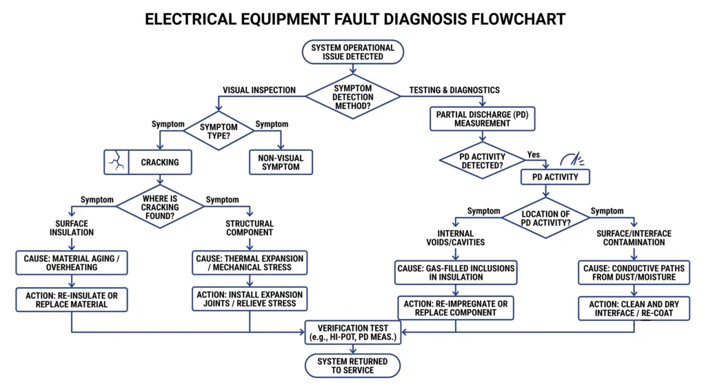
Flowchart mapping over-torque and under-torque symptom patterns to root cause diagnosis and corrective field action for MV bushings.For related failure patterns in bushing well interfaces, see ZeeyiElec’s bushing well inserts series page.
Standards References and Authority Sources
MV bushing mounting and torque practices sit within a broader framework of transformer accessory standards, giving installation crews a documented basis for their procedures rather than relying on a manufacturer chart alone.
IEEE C57.19.01 governs performance characteristics and dimensional standards for outdoor apparatus bushings, including creepage distance requirements by voltage class — the same margins referenced earlier when discussing flange distortion from over-torquing. IEC 60137 covers comparable scope for bushings used in AC systems above 1 kV, including routine and type test requirements a bushing should have passed before field installation. Where a project specification references one standard over the other — common in mixed IEC/IEEE regions such as parts of the Middle East and Latin America — installation crews should confirm which framework the specific bushing was manufactured and certified against, since torque and gasket seating tolerances can differ subtly between the two.
CIGRE Technical Brochure 755, developed by Working Group A2.43 on transformer bushing reliability, documents bushing in-service failure mechanisms and their relationship to broader transformer failure statistics based on international survey data, reinforcing why torque control deserves the same procedural rigor as electrical testing during commissioning.
Post-Installation Verification and Commissioning
Torque control doesn’t end when the wrench is put down on an MV bushing installation — a proper commissioning sequence confirms the installation will hold up under thermal cycling and load, not just at the moment of assembly.
Visual Re-Check and Torque Re-Verification
After the final staged torque pass, a documented spot-check with a calibrated torque wrench on at least 25% of bolts (rotating which bolts are checked between commissioning visits) helps catch any joint that relaxed after initial tightening. This is typically repeated once the transformer reaches normal operating temperature, since thermal expansion can shift clamping force from the as-installed cold state.
Insulation Resistance / PD Testing
Insulation resistance testing, generally at 5 kV to 10 kV DC depending on bushing class, along with a partial discharge check, should be run before energization to confirm the sealing interface achieved earlier didn’t leave measurable moisture or air gaps at the flange.
Getting torque values right the first time starts with using bushings and gaskets sized correctly for the application. ZeeyiElec’s medium-voltage bushings come with manufacturer-specific torque charts included in the technical documentation, and the team can help match flange dimensions and gasket specifications to your existing transformer turret before installation day. For full product specs and RFQ support, visit ZeeyiElec’s transformer accessories page.
Frequently Asked Questions
What torque should be applied to an MV bushing mounting bolt?
Torque values typically range from moderate to high depending on bolt diameter and bushing class, and should always follow the OEM-specified chart rather than a generic figure, since flange design varies by manufacturer.
Can over-torquing damage a bushing?
Yes — excessive torque can crack porcelain housings or deform epoxy interfaces, particularly in colder ambient conditions when materials are less compliant.
How do you know if a bushing gasket is properly seated?
A properly seated gasket shows uniform compression around the full circumference with no visible gaps, though final confirmation typically requires a torque re-check after initial settling.
What causes partial discharge after bushing installation?
Under-torqued bolts or contaminated sealing surfaces are common causes, since incomplete gasket compression can leave microscopic air gaps that ionize under voltage stress.
Should bushings be torqued in a star pattern?
Yes, a star or cross pattern is standard practice for most flanged bushings to ensure even gasket compression, though the exact sequence depends on bolt count and flange geometry.
How long after installation should torque be re-verified?
Many field technicians re-check torque after a short settling period following initial energization, as gasket materials can experience minor relaxation under thermal cycling.
Does ambient temperature affect bushing torque application?
Yes — cold conditions can make gaskets stiffer and porcelain more brittle, so torque should generally be applied more conservatively and re-verified once temperatures stabilize.
yoyo shi
Yoyo Shi writes for ZeeyiElec, focusing on medium-voltage accessories, transformer components, and cable accessory solutions. Her articles cover product applications, technical basics, and sourcing insights for global electrical industry buyers.





 English
 한국어
한국어 العربية
 Español
 हिन्दी
 தமிழ்
தமிழ் Deutsch (Sie)
 Français
 Português do Brasil
 Русский