An MV bushing drawing review is the last checkpoint before a medium-voltage bushing design commits to tooling and production. Once a supplier releases a drawing for manufacturing, changing a dimension, a creepage path, or a terminal configuration means re-cutting molds or re-machining fixtures — a cost and schedule hit that dwarfs the few hours a careful review takes. The reviewer’s job is not to redesign the bushing; it is to confirm that every value on the drawing traces back to a documented project requirement, not a supplier’s default catalog assumption.
What the Review Verifies
The review confirms three things simultaneously: that electrical parameters match the system’s insulation coordination study, that the mechanical interface matches the transformer tank the bushing will mount to, and that material callouts match the environmental class specified for the installation site. Missing any one produces a bushing that passes the supplier’s own factory acceptance test yet still fails to fit — or fails to survive — on site.
Why This Gate Matters Before Manufacturing
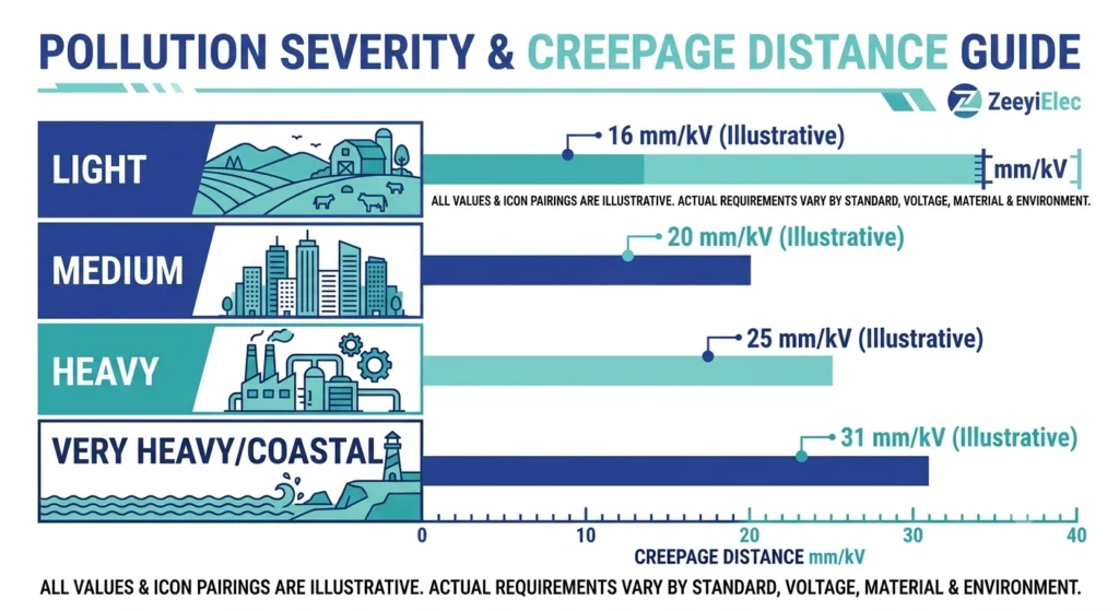
In field experience, the most expensive drawing errors are rarely gross mistakes; they are single-field omissions that survive because they look plausible in isolation. A drawing showing a 95 kV BIL rating on a bushing destined for a 25 kV class system with a 125 kV BIL requirement will read as internally consistent to anyone who doesn’t cross-check it against the insulation coordination table.Creepage distance is another frequent blind spot: a drawing specifying 25 mm/kV of creepage corresponds to IEC TS 60815 pollution severity class III (Heavy) — adequate for a moderately polluted site but undersized for a coastal or industrial environment classified as class IV (Very Heavy), which requires a minimum of 31 mm/kV.
Drawing review functions as a distinct gate separate from incoming inspection or factory acceptance testing — it catches specification drift before a single unit is molded, when correction costs a revision cycle rather than a scrapped production run.
[Expert Insight]
Drawing revision costs almost always beat re-manufacturing costs — push corrections upstream whenever possible
Treat every drawing as unverified until each field traces to a source document
Log past drawing-approval errors per supplier — patterns repeat across projects with the same factory
Electrical Parameters to Verify Before Sign-Off
The electrical block carries the highest failure consequence if misread, since these values determine whether the bushing survives normal operation and transient overvoltage events. Four fields deserve line-by-line comparison against the insulation coordination study or single-line diagram, not a glance-and-approve pass.
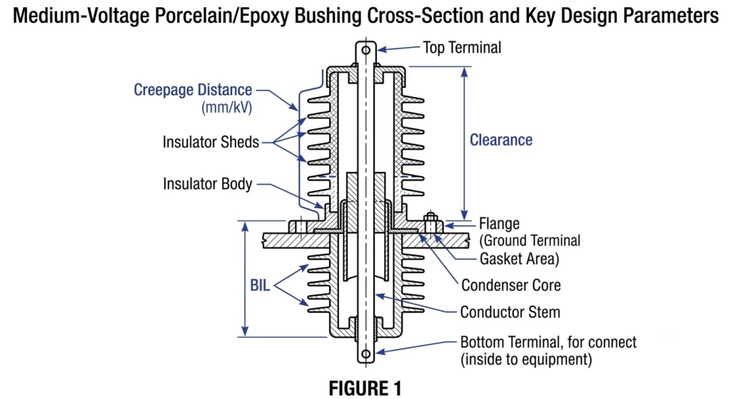
Cross-sectional view of a medium-voltage bushing with the creepage path along the insulator surface and clearance distance through air both labeled for drawing-review reference.
Voltage Class and BIL
Rated voltage (Um) and Basic Impulse Level (BIL) must match the system’s highest voltage and lightning-impulse withstand requirement, not just nominal distribution voltage. A system running at 24 kV nominal commonly requires a 25 kV bushing class with a 125 kVp BIL rather than the lower 95 kVp rating sometimes offered as a cost-reduced default — the two ratings look similar on a spec sheet but represent a meaningfully different insulation margin under switching surge conditions.
Current Rating and Conductor Sizing
Rated continuous current must be checked against the transformer’s actual full-load current at the relevant winding, including any planned overload margin, not just nameplate current. A bushing drawn for 630 A continuous current will run hot on a system with sustained 25% overload allowance unless the conductor stem cross-section was sized with that margin in mind.
Creepage Distance and Pollution Class
Creepage distance, expressed in mm per kV of rated voltage (mm/kV), must correspond to the site’s pollution severity class rather than a generic default. A drawing showing a specific creepage figure without a stated pollution class reference is incomplete regardless of whether the number itself looks adequate.
BIL and voltage class get checked almost automatically since they appear prominently on both drawing and RFQ. Creepage distance is the field most often left unverified, because it requires cross-referencing a separate environmental document not always attached to the drawing package — a gap worth closing before approval, consistent with the interface-level physics in How to Choose MV Bushings by Voltage Class and Environment.
Mechanical and Interface Dimensions to Verify
Electrical parameters determine whether a bushing survives its rated duty; mechanical dimensions determine whether it physically mounts to the tank at all. A drawing with correct BIL and creepage can still be unusable if flange pattern, mounting hole spacing, or terminal thread doesn’t match.
Flange Pattern and Mounting Hole Spacing
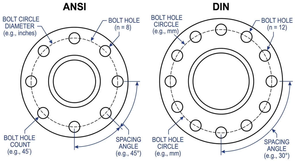
Side-by-side comparison of ANSI and DIN flange bolt-circle patterns, illustrating why mounting interfaces are not interchangeable between the two standards.
The flange must match the tank cutout it seats into — bolt circle diameter, hole count, and spacing all trace back to the transformer manufacturer’s drawing or an agreed standard interface, not an assumed “universal” pattern. ANSI and DIN mounting conventions differ enough in hole spacing and flange profile that a bushing drawn to one standard will generally not bolt onto a tank cut for the other, even at matching voltage and current ratings.
Terminal Configuration and Thread Size
A reference chart mapping site pollution severity — light, medium, heavy, and coastal — to the minimum creepage distance a bushing drawing should specify.
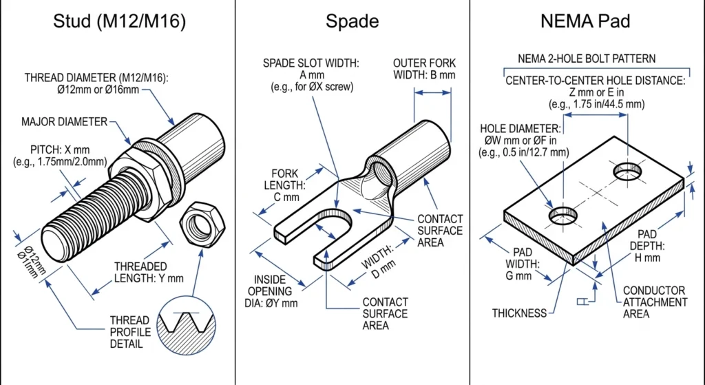
Terminal stud thread size and configuration (stud, spade, NEMA pad) must match the external connector or cable lug the site will use. A drawing specifying an M12 stud where project lugs are sized for M16 forces a field substitution that can compromise contact pressure and long-term joint reliability.
Overall Height and Immersion Depth
Total bushing height and immersion depth below the tank flange must be checked against internal clearance to windings and other components. A bushing drawn a few centimeters longer than the original interface can intrude into the winding clearance zone — a risk governed by the transformer manufacturer’s internal insulation coordination design (informed by the insulation levels defined in IEC 60076-3, Power transformers – Part 3), a risk that only surfaces during physical fit-up if uncaught on the drawing.
In factory acceptance and commissioning work, flange and thread mismatches are the errors most likely to reach the receiving dock undetected — the bushing tests fine on the bench and only fails to fit once a crew tries to install it. Cross-checking overall dimensions against the transformer manufacturer’s tank drawing, not just the bushing’s own datasheet, catches this before shipment, a discipline that carries through into MV Bushing Installation and Torque Control Checklist once the correct unit is on site.
Material and Environmental Class Verification
Material callouts exist to match the unit to its installation environment, not just to specify a manufacturing process. Correct electrical and mechanical parameters mean little if the insulation material or housing type doesn’t suit the site’s contamination, temperature, or UV exposure profile.
Three common MV bushing terminal configurations — stud, spade, and NEMA pad — shown together to illustrate why thread size must be confirmed against connector type.
Insulation Material: Porcelain vs. Cast Epoxy
The drawing should state the insulation material explicitly — glazed porcelain or cast epoxy resin — along with applicable pollution class, rather than leaving material selection to a default. Porcelain remains standard for high-pollution outdoor sites due to its washable glazed surface, while cast epoxy is typically favored for compact indoor switchgear where mechanical robustness during handling matters more than washability. Specifying one where the site calls for the other is a mismatch that won’t appear until the unit is in service and starts tracking or flashing over prematurely.
Ambient Temperature and Thermal Class
Ambient temperature range must reflect the actual installation site, not a generic mid-latitude default. A bushing rated for a standard −25°C to 40°C ambient range may be undersized for a site with sustained 45°C+ summer ambient combined with high load factor, since insulation aging rate accelerates meaningfully above its rated class.
In coastal and heavily industrial sites, a recurring field pattern is a drawing specifying standard-grade epoxy or a moderate creepage figure because the RFQ never flagged the site as high-pollution. The bushing performs normally in bench testing and for the first several months in service, then develops surface tracking as salt deposition accumulates — a failure traceable directly to a drawing approved without an environmental class cross-check, consistent with the material guidance in Choosing MV Bushings for Coastal and Polluted Environments.
[Expert Insight]
Never approve a drawing where material grade is inferred from price tier rather than stated pollution class
Ask suppliers to state ambient temperature assumptions explicitly — “standard rating” is not a specification
Default to the next pollution class up when site data is incomplete, not the lowest common denominator
Quick-Reference Drawing Review Checklist
The three parameter groups above — electrical, mechanical, material/environmental — consolidate into a single pass/fail reference for reviewers to work through before signing off.
MV Bushing Drawing Review Checklist
Category
Field to Verify
Cross-Check Against
Electrical
Rated voltage (Um) and BIL
Insulation coordination study / single-line diagram
Electrical
Rated continuous current
Transformer full-load current + overload margin
Electrical
Creepage distance (mm/kV)
Site pollution severity class
Mechanical
Flange pattern and bolt circle
Transformer tank cutout drawing (ANSI or DIN)
Mechanical
Terminal thread size/type
Cable lug or connector spec
Mechanical
Overall height and immersion depth
Transformer internal clearance data
Material
Insulation material (porcelain/epoxy)
Site pollution class and indoor/outdoor exposure
Material
Ambient temperature rating
Site climate data, including peak summer ambient
A drawing passing every row still deserves one final check: confirming values on the drawing match the accompanying test certificate or datasheet, since discrepancies between the two are as common as errors on the drawing itself. In field commissioning work, this cross-check has caught cases where a supplier updated a datasheet after a revision request but left the CAD drawing on the prior revision — invisible unless the documents are compared side by side.
Get Your MV Bushing Drawing Reviewed Before Committing to Production
A drawing review takes a few hours; a mismatched bushing discovered after installation costs weeks of delay and a re-manufactured unit. If a supplier drawing is awaiting sign-off, running it through the electrical, mechanical, and material checks above — before approval, not after receipt — is the difference between catching an error on paper and catching it in the field.
ZeeyiElec supports project teams through this review stage directly, cross-checking drawings against your insulation coordination data, tank interface requirements, and site environmental class before manufacturing begins. This applies whether you’re sourcing standalone transformer accessories — bushings, bushing wells, tap changers, fuse assemblies — or coordinating a project that also involves underground cable interfaces, where cable accessories termination and joint drawings carry an equivalent set of dimensional and material checks.
Share your bushing drawing package and project specification, and our engineering team will flag any field that doesn’t trace back to a documented requirement before you commit to tooling.
Frequently Asked Questions
What is the most commonly missed field in an MV bushing drawing review?
Creepage distance and its associated pollution class are the fields most often left unverified, since they require cross-referencing a separate environmental document rather than appearing directly on the drawing itself.
How long should a drawing review take before approval?
A structured review against electrical, mechanical, and material checklists typically takes a few hours per drawing, far less than the weeks a re-manufactured or field-modified bushing would add to a project.
Can a drawing pass electrical checks but still fail mechanically?
Yes — a bushing can carry correct voltage, BIL, and current ratings while still having a flange pattern or terminal thread that doesn’t match the transformer tank, since these are verified against entirely different reference documents.
Do ANSI and DIN bushings use the same mounting pattern?
No, ANSI and DIN standards use different bolt circle diameters and flange profiles, so a bushing drawn to one standard generally will not bolt onto a tank cutout prepared for the other, even at matching voltage and current ratings.
Why does ambient temperature matter on a bushing drawing?
Ambient temperature rating affects insulation aging rate, so a bushing rated for a standard temperature range may age faster than expected at sites with sustained high summer ambient combined with high load factor.
Should the drawing or the datasheet take priority if they conflict?
Neither should be trusted by default — a conflict between drawing and datasheet values usually indicates one document wasn’t updated after a revision, so the discrepancy itself should trigger a query back to the supplier before approval.
Is porcelain always the safer choice for outdoor MV bushings?
Not universally — porcelain suits high-pollution outdoor sites due to its washable surface, but cast epoxy is often preferred for compact or indoor installations where mechanical robustness matters more than washability, so the choice depends on site conditions.
yoyo shi
Yoyo Shi writes for ZeeyiElec, focusing on medium-voltage accessories, transformer components, and cable accessory solutions. Her articles cover product applications, technical basics, and sourcing insights for global electrical industry buyers.





 English
 한국어
한국어 العربية
 Español
 हिन्दी
 தமிழ்
தமிழ் Deutsch (Sie)
 Français
 Português do Brasil
 Русский