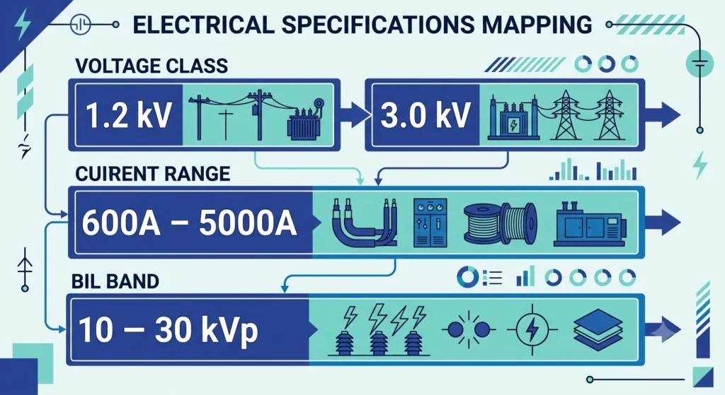
A low voltage ceramic bushing is an insulated pass-through component mounted on a distribution transformer’s tank wall, providing a sealed path for secondary-side current to exit the oil-filled enclosure without shorting to the grounded tank. Unlike medium voltage bushings, which manage concentrated dielectric stress fields, this component’s primary engineering burden is thermal — it carries continuous current typically in the 600 A–5000 A range at a rated voltage class of 1.2 kV–3.0 kV, so heat rejection at the conductor-insulation interface matters more than surge withstand.
Core Structural Elements
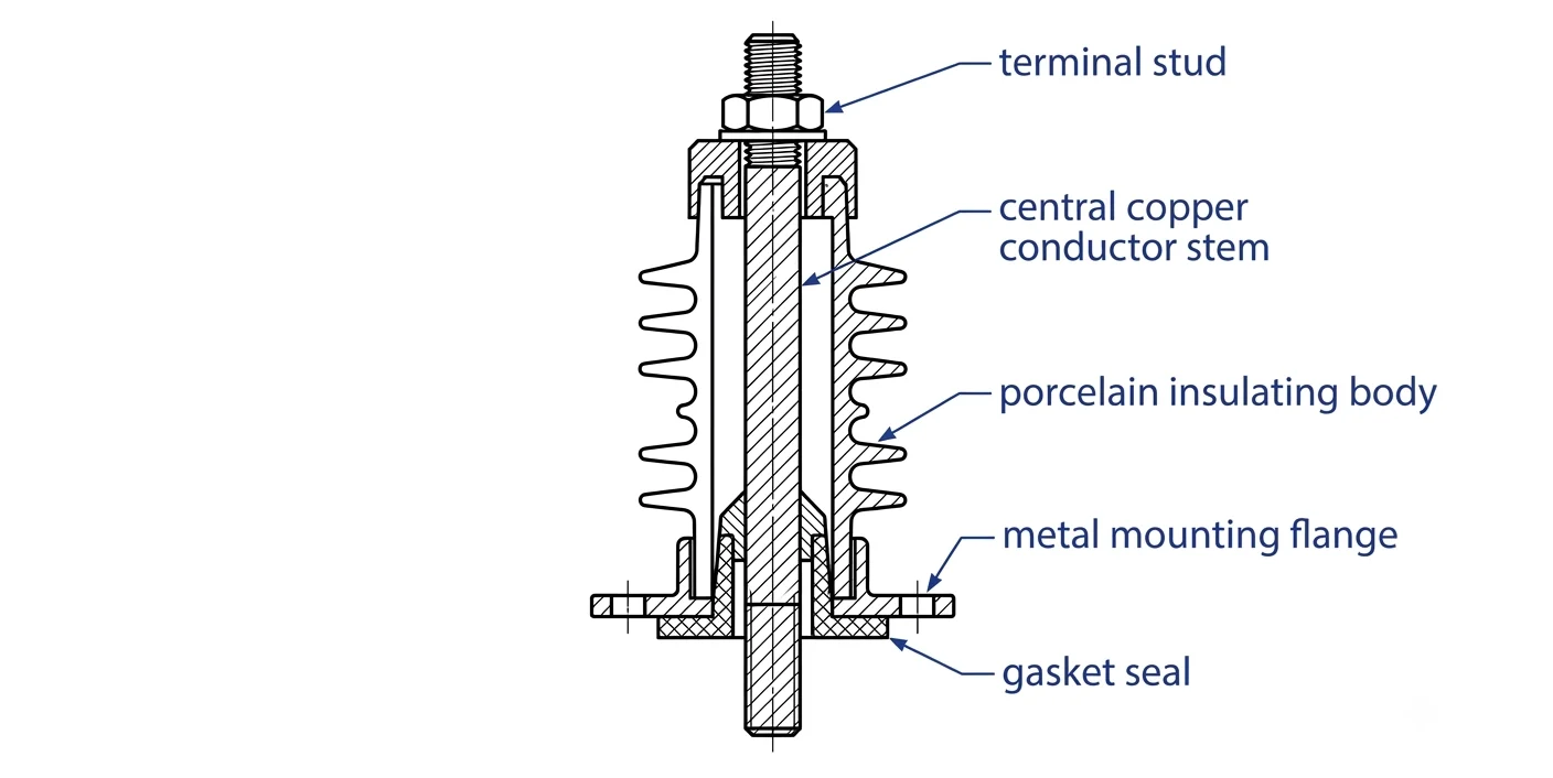
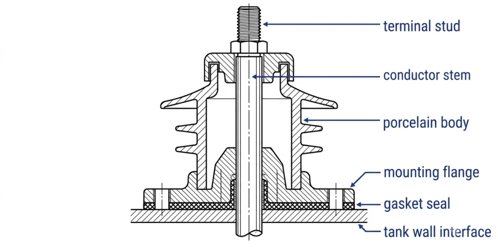
The design centers on a central conductor stem, usually a copper or copper-alloy rod machined to accept a threaded terminal stud at the external end. This stem passes through a porcelain insulating body — kiln-fired at high temperature to achieve a dense, low-porosity structure — bonded or mechanically sealed to a metal mounting flange. The flange interfaces with the tank wall through a gasketed seal, and on some designs a spring-loaded or bolted clamp maintains consistent compression as the unit thermal-cycles between ambient and full-load operating temperature.
In field terms, the porcelain shell functions purely as the dielectric and mechanical housing; it does not carry current. Current transfer performance is governed entirely by the stem’s cross-sectional area and terminal connection quality, which is why installation torque control matters as much as material selection — a point covered further below.
Where It Sits in the Transformer Secondary Circuit
On a typical 25 kVA–2500 kVA distribution transformer, this bushing type sits where internal secondary windings connect to external LV cabling or busbar. It’s one of several accessory options performing this function alongside HTN and porous resin bushings — the material choice shifts based on current density, ambient exposure, and mechanical handling risk on site, a distinction the next section breaks down directly.
Cross-section of a ceramic LV bushing highlighting the conductor stem, porcelain shell, and gasketed mounting flange interface.
Low Voltage Ceramic Bushing vs HTN vs Porous Resin: Material Comparison
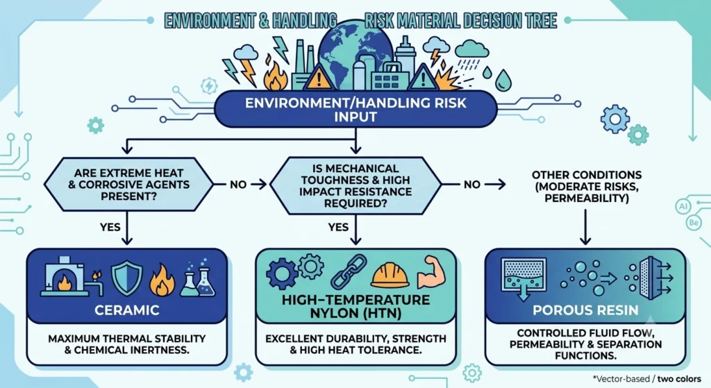
Selecting between porcelain, HTN, and porous resin comes down to matching material properties to current density, ambient exposure, and mechanical handling risk during transport and installation. All three meet the same functional requirement — insulating the conductor stem from the grounded tank — but they diverge in thermal behavior, impact resistance, and long-term surface performance.
Porcelain / Ceramic
Manufactured from a fired blend of clay, quartz, and alumina, vitrified at high kiln temperatures to produce a dense, chemically inert surface. This gives strong resistance to UV degradation and chemical attack, which is why it remains common for outdoor pad-mount installations in coastal or industrial-pollution environments. The trade-off is brittleness: porcelain has no give under impact, so a dropped unit or a wrench slip during installation can chip or crack the housing in a way HTN would simply dent or scuff.
HTN (High Temperature Nylon)
A thermoplastic polymer selected for impact resistance and lighter weight — a meaningful factor when field crews handle and position bushings rated up to 5000 A on live job sites. HTN typically tolerates continuous operating temperatures in the 140°C–150°C range at the insulation surface, comparable to porcelain, but its polymer structure is more susceptible to long-term UV chalking under direct, unshielded sun exposure.
Porous Resin
A cast, filled epoxy body that sits between porcelain and HTN in mechanical toughness. Resin handles thermal cycling well and resists cracking better than porcelain under mechanical shock, though its dielectric surface can be more sensitive to moisture absorption over time if the outer coating is compromised — a consideration in high-humidity substation environments.
Coastal or high-pollution sites favor porcelain’s chemical inertness over polymer alternatives
High-turnover or field-replaceable stock does better in HTN, which tolerates handling shock
Never assume material interchangeability on an RFQ — confirm which material a quoted “LV bushing” line item actually specifies
Low Voltage Ceramic Bushing Ratings: Voltage, Current, and BIL
Rating this bushing type correctly requires reading three interdependent parameters together — rated voltage class, continuous current, and basic impulse insulation level (BIL) — rather than treating any one figure as sufficient on its own.
Voltage Class and Rated Maximum Voltage
Units are typically rated at 1.2 kV or 3.0 kV maximum system voltage, even though the transformer’s actual secondary voltage may sit well below that ceiling. This margin exists because the bushing must tolerate transient overvoltages from switching events and nearby lightning activity, not just steady-state operating voltage.
Current Rating Range
Continuous current rating commonly spans 600 A to 5000 A, with the conductor stem’s cross-sectional area — not the porcelain body — setting the practical ceiling. A unit sized for 3000 A carrying only 1200 A of actual load runs cooler and sees reduced thermal aging at the seal interface, which is one reason field engineers oversize slightly on high-duty-cycle installations rather than matching nameplate current exactly.
BIL and Insulation Coordination
Basic Impulse Insulation Level defines the peak voltage a bushing must withstand under a standardized impulse waveform without flashover. LV ceramic bushings are generally coordinated to withstand impulse levels in the range of 10 kVₚ–30 kVₚ, though this figure should always be cross-checked against the specific transformer’s insulation coordination study rather than assumed from voltage class alone.
Selecting a bushing with a BIL below the system’s coordinated withstand level creates a weak point in the insulation chain — under a transient event exceeding roughly 15 kVₚ–20 kVₚ, an under-rated unit can flash over before upstream protection operates.
Impulse test methods for distribution-class bushings under 34.5 kV are governed by IEEE Std C57.12.00, though installers should confirm the exact voltage/current combination against the applicable table in the current edition.
Impulse test methods for distribution-class bushings under 34.5 kV are governed by IEEE Std C57.12.00, though installers should confirm the exact voltage/current combination against the applicable table in the current edition.
For full voltage-class and current-rating breakdowns across ZeeyiElec’s bushing portfolio, see the transformer accessories product line.Ratings overview mapping LV ceramic bushing voltage class, continuous current range, and typical BIL band for distribution transformers.
Field Installation and Torque Considerations
Installation quality determines whether this bushing performs to its rated current for decades or develops a hot terminal within the first year of service. Two variables dominate: gasket seating and torque control.
Mounting and Gasket Seating
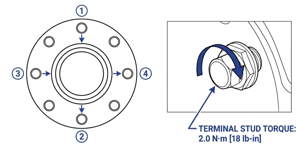
The flange seats against the tank wall through a compressible gasket, typically rated across a wide ambient range spanning roughly -30°C to 105°C at the sealing surface. Crews commissioning pad-mount units should confirm even compression around the full flange circumference — an uneven seat, often from a warped mounting surface or a bolt tightened out of sequence, creates a localized gap that becomes a moisture ingress path over repeated thermal cycles. On porcelain units specifically, uneven flange loading carries an added risk: because ceramic has no mechanical give, concentrated stress at one point can initiate a hairline crack that doesn’t show up until months later under vibration or thermal cycling.
Terminal Torque and Contact Reliability
Contact resistance at the bolted terminal joint is governed by actual metal-to-metal contact area, which expands as clamping force increases — up to the point where the terminal material begins to yield. Under-torquing leaves excess resistance that, under a 3000 A–4000 A continuous load, can generate enough I²R heating to visibly discolor the terminal within a single duty cycle. Over-torquing risks deforming the stud threads or, on porcelain units, transmitting excess mechanical stress into the ceramic-to-metal seal at the base of the stem.
Field experience across pad-mount commissioning work shows torque values should always be pulled from the specific datasheet rather than assumed from a general LV hardware chart — stud diameter and thread pitch vary enough between manufacturers that a generic table can under- or over-clamp the joint. Recheck torque after the first thermal cycle where practical, since initial seating can relax slightly.
Recommended bolt-tightening sequence and terminal torque staging for ceramic LV bushing installation on a distribution transformer.For a full field verification sequence, see the LV bushing installation torque and contact reliability guide.
[Expert Insight]
Check flange compression evenly around the full circumference, not just in a single bolt pass
Pull torque specs from the specific datasheet, not a generic LV hardware chart
Recheck terminal torque after the first thermal cycle, since seating can relax slightly
Common Field Failure Patterns in Low Voltage Ceramic Bushings
Ceramic units fail in patterns distinct enough from HTN or resin that field diagnosis usually starts by identifying which mechanism is at play: thermal cracking, physical impact damage, or surface contamination tracking.
Thermal Cracking
Repeated cycling between full-load operating temperature and cold ambient conditions stresses the bond line where the porcelain body meets the metal flange and stem. Over years of service — commonly in the 15–25 year range before symptoms appear — this can produce hairline cracks at the seal, particularly on units that experienced a prior mechanical stress event such as an uneven flange installation. A crack here rarely causes immediate failure; instead it opens a slow moisture ingress path that eventually degrades the internal seal.
Chip and Impact Damage
Because porcelain has essentially no mechanical give, impact damage during shipping, handling, or installation tends to show as visible chipping rather than the scuffing seen on HTN bodies. A chip near the current-carrying stem is more serious than one on the outer skirt, since it can shorten the surface creepage path and increase flashover risk under transient conditions. Any chipped unit found during pre-installation inspection should be rejected rather than installed on the assumption it will “hold.”
Surface Contamination Tracking
Tracking develops when surface leakage current acts on contamination and moisture on the skirt, gradually forming a carbonized conductive path. This mechanism progresses slowly and is one of the more preventable failure modes — cleanliness and inspection at 12–24 month intervals in polluted or coastal environments typically catches it before a critical stage. Treat any visible discoloration or fine carbon streaking as an early warning sign, since tracking accelerates once it starts.
Porcelain remains the right call in a specific band of applications — primarily fixed outdoor installations facing sustained UV or chemical exposure, where its inert surface outlasts polymer alternatives.
Best-Fit Applications for Ceramic
This material performs best on pad-mount transformers in coastal, industrial-pollution, or high-UV environments where a unit will sit exposed for its full 20–30 year service life without frequent handling. Chemical inertness resists the surface degradation that gradually chalks or dulls polymer housings under continuous sun exposure, and dielectric stability holds up across the full 1.2 kV–3.0 kV rating range without special coating maintenance.
Where HTN or Resin Outperforms Ceramic
HTN is the better fit wherever bushings face repeated handling — high-turnover distribution stock, field-replaceable units, or sites with elevated vibration from nearby heavy equipment — since its impact tolerance avoids the chip-and-crack risk inherent to porcelain. Porous resin suits humidity-controlled substation environments where moderate mechanical toughness matters more than UV resistance.
Matching material to environment upfront avoids a costly mismatch: a chipped or cracked porcelain unit in a high-vibration site often needs replacement well inside its rated service life, while HTN in a dirty coastal environment may chalk sooner than porcelain would. If you’re specifying LV bushings for a new distribution project, ZeeyiElec’s engineering team can help match voltage class, current rating, and material to your site conditions — reach out for RFQ support and technical drawings before finalizing your accessory spec.
Material-selection decision flow matching site environment and handling risk to ceramic, HTN, or porous resin LV bushing choice.For broader selection criteria across the full transformer accessory range, see the transformer accessories selection guide.
Frequently Asked Questions
How long does a ceramic LV bushing typically last in service?
Ceramic LV bushings commonly reach 20–30 years of service under normal thermal cycling, though coastal or heavily contaminated environments can shorten that range if surface cleaning isn’t maintained.
Is ceramic or HTN better for a low voltage bushing?
Ceramic offers stronger resistance to UV and chemical exposure, while HTN is lighter and more impact-resistant during handling and transport — the better choice depends on installation environment and mechanical risk on site.
What current rating can a ceramic LV bushing handle?
These units are generally available across the same 600 A–5000 A+ range as other LV bushing materials, with the practical ceiling set more by conductor stem sizing than by the porcelain body itself.
Can a cracked ceramic bushing still be used temporarily?
A cracked or chipped porcelain bushing should not remain in service, since even hairline cracks can become a moisture ingress and tracking path under load — replacement is the safer path once damage is confirmed.
Why do ceramic bushings crack in cold climates?
Thermal cycling between hot load conditions and cold ambient temperatures creates stress at the porcelain-to-metal seal interface, and repeated cycling over many years can eventually produce hairline cracking, particularly on units with prior mechanical stress.
Do ceramic bushings need different torque specs than resin bushings?
Torque specifications are generally driven by the terminal stud and connector hardware rather than the insulating body material, but installers should still confirm manufacturer-specific torque values since flange designs vary between ceramic and resin product lines.
yoyo shi
Yoyo Shi writes for ZeeyiElec, focusing on medium-voltage accessories, transformer components, and cable accessory solutions. Her articles cover product applications, technical basics, and sourcing insights for global electrical industry buyers.





 English
 한국어
한국어 العربية
 Español
 हिन्दी
 தமிழ்
தமிழ் Deutsch (Sie)
 Français
 Português do Brasil
 Русский