연락처 정보
지이일렉은 글로벌 유통업체와 프로젝트 계약업체를 위한 변압기 및 케이블 액세서리를 공급합니다. 기술 선택 및 RFQ 지원은 당사에 문의하세요.
주소:
리우시, 웨칭, 원저우, 저장성, 중국
전화 / WhatsApp / 위챗:
+86 150 5877 8024
이메일:
[email protected]


안정적인 품질, 실용적인 리드 타임, 수출 지원으로 공장에서 직접 부품을 조달하세요.
아래 양식을 작성하여 카탈로그와 가격을 받아보세요.

 으로요요시
으로요요시The answers below cover the questions maintenance engineers and buyers raise most often about current-limiting fuses in distribution transformers.
A current-limiting fuse interrupts a high fault current before it reaches its unrestricted peak, typically within the first half-cycle, which cuts the peak current and let-through energy the transformer sees. In distribution transformers it usually serves as backup protection and cannot safely clear low-level overloads on its own.
Inside the body, silver or copper elements with reduced-section notches sit in a granular filler such as silica sand. At high fault current the notches vaporize almost together, and the filler absorbs arc energy and builds arc voltage that forces the current down before its first natural peak. A half-cycle is about 8.3 ms at 60 Hz and 10 ms at 50 Hz, while prospective fault current on distribution transformers can reach 50,000 A or more.
The thermal stress passed through the fuse is expressed as let-through energy, I2t, in A2·s. A current-limiting fuse keeps this value well below what the same fault would deliver if it ran for several cycles. Manufacturers publish peak let-through and I2t curves against prospective current, and these curves, not the ampere rating alone, show how much protection the fuse provides at a given fault level.
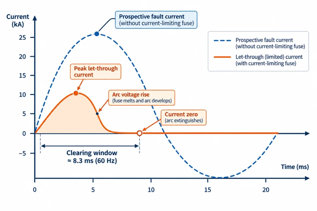
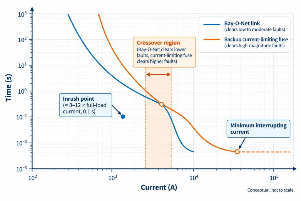
Most under-oil fuses are backup (partial-range) designs. They clear high-magnitude faults quickly but have a minimum interrupting current, often several times the continuous rating, so confirm the multiple on the datasheet. That is why they are paired in series with an expulsion device such as a Bay-O-Net fuse assembly, which handles overloads and lower fault currents. A high maximum interrupting rating does not mean the fuse can protect the transformer alone. See this current-limiting fuse backup protection guide.
A fuse operation shows that something exceeded the fuse’s duty, not what caused it. Sort the event into one of three patterns before handling a replacement.
Magnetizing inrush on a distribution transformer commonly reaches 8× to 12× full-load current and decays over roughly 0.1 s, although residual flux, switching angle and source strength shift these values. A backup fuse sized close to full-load current can be pre-damaged by repeated energizations, even if it does not blow the first time. Typical signs are a fuse that operates within seconds of closing, with no fault evidence on the transformer, or one that fails after a run of re-energizations during a switching sequence.
Crews restoring a pad-mounted unit after a long outage often re-close several times in quick succession, stacking thermal stress on the element. Compare the fuse’s inrush withstand data with the transformer’s inrush profile before calling it defective.
This usually points to a coordination gap rather than a transformer defect. Check whether the Bay-O-Net link should have cleared first, and whether the site fault level fell between the two devices’ ranges.
This is what the backup fuse exists for. Evidence includes gas or pressure indication, oil discoloration, a burnt smell or a tripped pressure relief device. Do not re-fuse and re-energize until the unit has been tested.
| 증상 | Likely pattern | First check |
|---|---|---|
| Operated within seconds of closing | Inrush | Fuse inrush withstand vs. transformer data |
| Operated during heavy loading | Overload or coordination gap | Load history, Bay-O-Net link rating |
| Operated with a nearby downstream fault | External fault | Fault level, device coordination |
| Operated with gas, pressure or oil signs | Internal fault | Isolate; test before re-energizing |
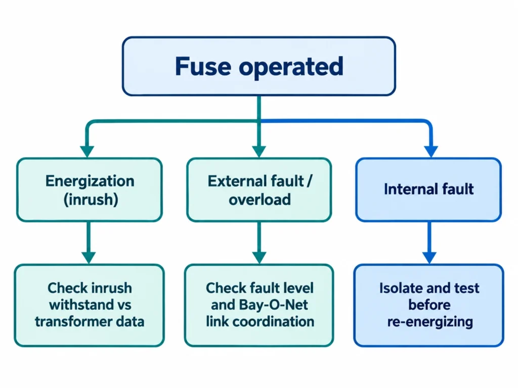
For a structured approach to root cause, see this 현장 장애 진단 워크플로.
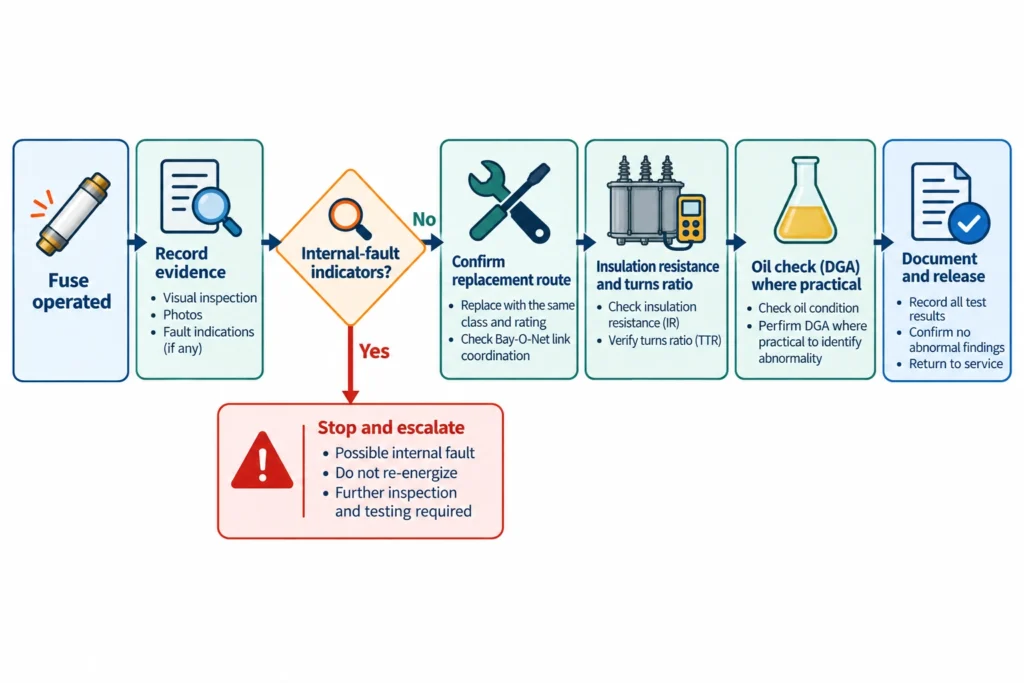
Replacing a fuse restores continuity, not fitness for energization. Treat them as separate decisions and follow the manufacturer’s service instructions where they differ from this sequence.
Insulation resistance is commonly read with a 2.5 kV to 5 kV megohmmeter, depending on the winding voltage class, and compared against the unit’s own history and manufacturer guidance rather than a single universal MΩ figure. Turns ratio is compared with the nameplate ratio, and a deviation within about ±0.5% on the principal tapping is a common acceptance figure; the binding limit is the one in the transformer’s test report or project specification.
Pressure to restore supply within a 4 h to 6 h outage window is the main reason step 4 gets skipped, yet a fuse that cleared once may have contained an internal fault. See replacing a current-limiting fuse after a fault for a fuller checklist.
Rating a fuse from kVA and voltage alone is the most common source of nuisance operation. A correct match combines full-load current, inrush, fault level and coordination with the series device.
Start with full-load current. For a 500 kVA three-phase unit at 12.47 kV, I = 500 kVA ÷ (√3 × 12.47 kV) ≈ 23 A. Inrush at 8× to 12× full-load current for about 0.1 s puts the energization point near 185 A to 280 A, and the fuse’s time-current curve must sit clear of that point. Fuses in distribution service are commonly offered in 15.5 kV, 25 kV and 40.5 kV classes, and the class must cover the system’s highest voltage, not just its nominal value.
Impedance (%Z) limits the fault current the fuse must interrupt, and a low-impedance unit on a strong source can approach the fuse’s upper interrupting rating.
| Item to confirm | 중요한 이유 |
|---|---|
| Voltage class and highest system voltage | Sets dielectric and interrupting capability |
| 연속 전류 정격 | Must carry full load plus permitted overload |
| Inrush withstand | Prevents element damage on energization |
| Maximum interrupting rating | Must exceed prospective fault current at site |
| Minimum interrupting current | Defines the range the series device must cover |
| Fluid and temperature suitability | Under-oil duty changes continuous-current capability |
The devices should overlap without a gap. The Bay-O-Net link handles overloads and low-to-moderate faults, and the backup fuse takes over above the crossover point, where the link must clear before the backup fuse sees a current below its minimum interrupting capability. Utilities usually apply their own time margin.
Published curves usually start from ambient conditions with no prior load. Pre-loading, hot oil and repeated inrush shift real operating time to the left, so use curves to check ordering, not to promise exact clearing times.
IEC 60282-1 covers high-voltage current-limiting fuses for AC systems above 1 kV; confirm the exact fuse standard and test scope with the manufacturer’s datasheet for your transformer type.
Many post-energization problems begin in the warehouse. A sealed element cannot be inspected, so identity and handling records are the only evidence a spare is trustworthy.
No single shelf-life figure fits every design, so follow the manufacturer’s storage requirements. Keep spares indoors and dry, in original packaging with legible markings, typically at 5 °C to 40 °C with non-condensing humidity unless the datasheet says otherwise. Quarantine any unit with a cracked body, damaged end cap, missing label or unknown history. Field audits often find loose fuses from mixed lots with no packing slips, so nobody can say later which rating was installed.
Support the fuse on its designed mount, never through a stiff bus connection, which can loosen end-cap joints under thermal cycling. Torque terminals to the fuse instructions (bolted connections of this class commonly fall between 20 N·m and 40 N·m, depending on thread size) and verify clearances against the approved transformer drawing.
Confirm that the body, seals and adhesives suit the transformer’s fluid, mineral oil or ester. Incompatibility develops as swelling or seal softening over months at operating temperature.
A fuse enquiry with only a rating and a quantity forces the supplier to guess. A complete data set lets an engineer check the fuse against your transformer instead of your part number.
A credible reply names the fuse type (backup or full-range), minimum and maximum interrupting current, inrush withstand and fluid compatibility, with the datasheet and time-current curves.
Send this information with your enquiry through ZeeyiElec’s 변압기 액세서리 range, and our engineers will check the fuse against your transformer data before quoting. If the project also needs terminations or joints, include the cable details so one quote can cover your 케이블 액세서리 too.
Not as a first fix. A higher rating also raises the minimum interrupting current and can open a gap with the Bay-O-Net link, which on 25 kVA to 500 kVA units commonly falls between 2 A and 50 A, so check inrush and coordination data with the supplier first.
Look for a “backup” or “partial-range” designation and a stated minimum interrupting current on the datasheet or marking. If the marking is unreadable, send the part number to the manufacturer before installing anything.
Generally no, because a missing phase can cause single-phasing on three-phase loads and, on some cable-fed units, ferroresonance. Restore all three phases with approved fuses and follow your utility’s switching procedure.
It can. Above roughly 1,000 m lower air density reduces external dielectric strength, so clearances and voltage class may need review; under-oil fuses are usually less affected. Ask the supplier for altitude correction data.
A resistance or continuity check can screen for a broken element but cannot confirm interrupting performance. Real assurance comes from type-test evidence and routine-test records for the batch.

 English English
 한국어
한국어 العربية
 Español
 हिन्दी
 தமிழ்
தமிழ் Deutsch (Sie)
 Français
 Português do Brasil
 Русский