연락처 정보
지이일렉은 글로벌 유통업체와 프로젝트 계약업체를 위한 변압기 및 케이블 액세서리를 공급합니다. 기술 선택 및 RFQ 지원은 당사에 문의하세요.
주소:
리우시, 웨칭, 원저우, 저장성, 중국
전화 / WhatsApp / 위챗:
+86 150 5877 8024
이메일:
[email protected]


안정적인 품질, 실용적인 리드 타임, 수출 지원으로 공장에서 직접 부품을 조달하세요.
아래 양식을 작성하여 카탈로그와 가격을 받아보세요.

 으로요요시
으로요요시A 전류 제한 퓨즈 interrupts an overcurrent and, when operating in its current-limiting region, reduces the peak current and clearing I²t that would otherwise pass through the circuit. In a transformer protection system, a backup current-limiting fuse handles the higher-current part of the protection range together with a coordinated low-current protective device.
The key limitation is its minimum interrupting current. A backup fuse may melt at a current below the range it can safely interrupt. It therefore cannot be selected as the transformer’s only overload and fault protection simply because its maximum interrupting rating is high.
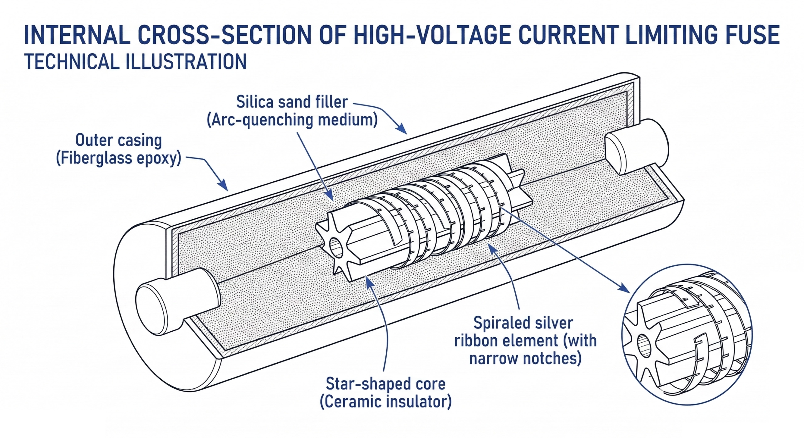
The banner is a conceptual cutaway of a sand-filled fuse. Materials, element geometry and mounting details vary by model; use the selected product’s datasheet and installation drawing.
Here, backup describes the fuse’s interrupting classification. It does not mean a spare fuse or a device that waits for another fuse to fail. In a series-connected arrangement, both protective devices carry the circuit current; their characteristics determine how the combination clears an event.
Keep three classifications separate:
| Classification | Low-current capability | Selection implication |
|---|---|---|
| Backup | Interrupting capability extends down to a specified minimum interrupting current. | Requires coordinated low-current protection. |
| General-purpose | Its defined interrupting range extends down to the current that melts the element in one hour. | Do not assume it covers every possible low-current melting condition. |
| 전체 주파수 대역 | Can interrupt currents that cause melting within its designated rating and conditions. | Still requires correct load, voltage, installation and protection selection. |
These distinctions are explained in Eaton’s utility fuse fundamentals. “Current-limiting” and “backup” are not interchangeable terms.
In a typical sand-filled design, excessive current melts sections of the fuse element and creates arcs. The filler helps cool and quench those arcs. In the current-limiting region, the resulting arc voltage drives the current to zero before its natural current zero, reducing the prospective peak.
Operating time depends on current and the exact fuse characteristic. Sub-half-cycle clearing applies in the current-limiting region; it is not a universal clearing time for every overload. Nor does a fuse guarantee that a faulted transformer remains serviceable or that tank damage is impossible.
Two different quantities describe the limitation:
Minimum-melting I²t covers the pre-arcing stage; total-clearing I²t includes arcing as well. Use the correct quantity and the stated test conditions. Eaton’s I²t testing note also explains why short-duration withstand matters for inrush and cold-load pickup.
A transformer arrangement may pair a backup fuse with a Bay-O-Net expulsion fuse or another approved interrupter. Eaton’s ELSP 카탈로그 CA132013EN, for example, describes series application with a Bay-O-Net fuse or MagneX interrupter. This is a product-specific application example, not approval for arbitrary combinations.
The coordination review must cover the backup fuse’s low-current limitation, the companion device’s maximum interrupting capability, and damage avoidance under permitted loading and surges. A fixed 3,000 A “handoff” or matching ampere labels cannot establish this.
Manufacturer methods may include TCC crossover and matched-melt coordination. Do not assume that the Bay-O-Net link remains intact whenever the backup fuse operates; the chosen method determines the intended behavior. See the ABB Trans-Guard application paper and our Bay-O-Net 및 전류 제한 퓨즈 연계 가이드 for the curve-review framework.
| 확인 | What the buyer or engineer needs |
|---|---|
| Voltage application | Maximum system voltage, winding connection, grounding and the manufacturer’s voltage-application rules. |
| Continuous loading | Transformer load, overload duty, inrush, cold-load pickup and the fuse’s service conditions. |
| Minimum interrupting current | The exact model’s lower interrupting limit and the device covering lower currents. |
| 최대 차단 전류 | A rating suitable for available fault current under the applicable voltage and circuit conditions. |
| Current-limitation data | Peak let-through, minimum-melting and clearing I²t data appropriate to the review. |
| Installation compatibility | Approved fluid or dry enclosure, temperature, mounting, clearances, terminals and dimensions. |
Rated amperes, minimum interrupting amperes and maximum interrupting amperes describe different limits. None should be substituted for another. Also distinguish fuse-generated arc voltage from recovery voltage after interruption. Transformer BIL is an insulation withstand rating, not a fuse operating threshold.
There is no universal 130%–140% sizing factor for under-oil fuses. Use the applicable manufacturer selection tables and thermal corrections, then confirm the complete protective combination.
Under-oil: specify a fuse approved for the actual insulating fluid and operating temperature. Fluid compatibility, mounting and clearances form part of the application; an air-rated fuse is not automatically suitable for immersion.
Dry-well: the fuse operates inside an enclosure separated from the fluid. Confirm the approved fuse-and-holder combination and its enclosure thermal limits. External accessibility does not by itself establish loadbreak capability or permission for energized replacement.
Follow the model-specific service instructions. For example, Eaton’s ELSP installation manual MN132001EN states that an ELSP operated by high fault current is not field replaceable and directs return of the transformer/fuse to the transformer manufacturer. This requirement should not be generalized into a repair procedure for every current-limiting fuse.
An operated fuse is a one-time device and cannot be reset. Its operation calls for investigation before re-energization, but does not by itself identify the failed component or establish the transformer’s condition.
Qualified personnel should follow the equipment manufacturer’s isolation, inspection, testing and replacement requirements. Retain fault records, fuse identification and information about the companion protective device. A damaged casing or the appearance of filler material alone is not a reliable root-cause diagnosis. See our current-limiting fuse replacement guide for the information to collect.
For current-limiting fuse enquiries, provide transformer kVA, voltages, phase count, connection, grounding, impedance and available fault current. Include existing fuse and holder catalog numbers, the companion device, insulating fluid, temperature requirements, installation dimensions and quantity.
사양서를 ZeeyiElec로 보내주세요 and request the proposed model’s datasheet, interrupting limits, TCC and current-limitation data, installation instructions and applicable pairing evidence. A physically similar fuse or identical ampere marking is insufficient evidence of interchangeability.
Do not rely on it below its specified minimum interrupting current. A backup fuse needs coordinated low-current protection. Full-range current-limiting fuses have different capabilities.
In sand-filled designs, the filler helps absorb heat and quench the arcs formed after the element melts. Exact construction and performance depend on the fuse model.
It can clear in less than half a cycle when operating in its current-limiting region. At other currents, use the selected fuse’s TCC; a fixed millisecond value does not describe its complete operating range.
No. It requires fault investigation and assessment under the equipment manufacturer’s procedures. Fuse operation alone does not identify the fault location or confirm that the transformer can return to service.
A Bay-O-Net is one possible companion device. Another approved low-current interrupter may be used where the manufacturer supports the combination. A backup fuse must not be treated as standalone full-range protection.
Use the selected fuse manufacturer’s temperature and application guidance for the actual fluid and operating conditions. There is no universal 130%–140% load multiplier for all under-oil backup fuses.

 English English
 한국어
한국어 العربية
 Español
 हिन्दी
 தமிழ்
தமிழ் Deutsch (Sie)
 Français
 Português do Brasil
 Русский