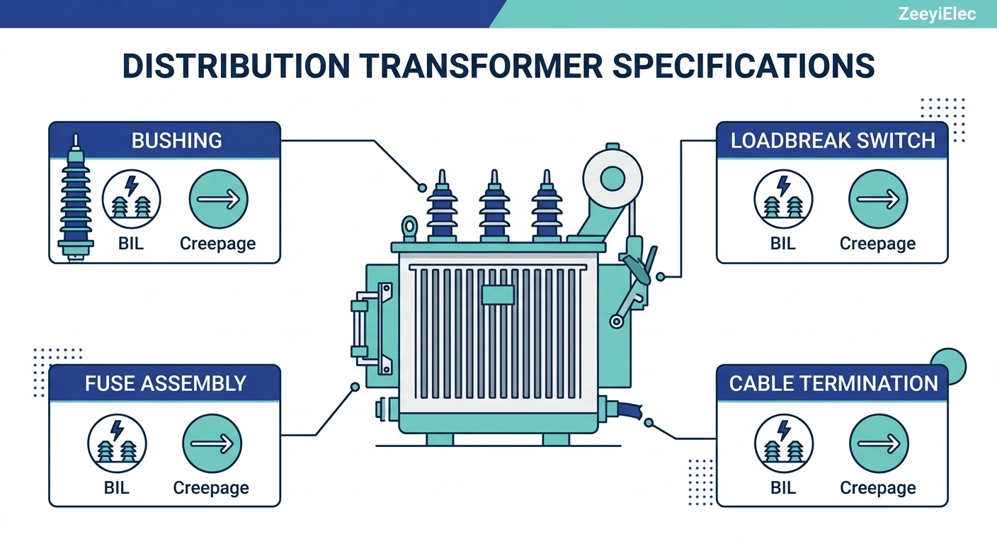
Insulation coordination is the process of selecting the dielectric withstand levels of transformer and cable accessories so they correlate with the voltage stresses the system can realistically impose, including both continuous operating voltage and transient overvoltages from lightning strikes or switching events. Rather than sizing each accessory in isolation, this process treats the transformer, its bushings, fuses, switches, and connected cable terminations as a single dielectric chain — the weakest link determines the system’s actual withstand capability, regardless of how well the strongest component is rated.
This matters at the accessory level because a distribution transformer’s nameplate voltage does not, by itself, specify what a bushing, tap changer, or cable termination must withstand. A 25 kV-class system does not simply require accessories rated “25 kV” — it requires accessories whose Basic Impulse Level (BIL) and creepage distance are matched to the system’s coordination study or, absent a project-specific study, to standard voltage-class tables. Two accessories can share an identical nominal voltage rating and still differ meaningfully in transient withstand capability if their BIL values diverge — a distinction surface-level catalog comparison often misses.
Why Accessories Inherit Coordination Requirements
Accessories do not set their own insulation requirements; they receive them from the system. A bushing well insert rated for 15 kV service, for instance, is expected to withstand impulse levels of roughly 95 kV to 125 kV BIL depending on the applicable standard and installation category — not because the insert itself generates that stress, but because it sits in a circuit where transients can appear. Field engineers who specify purely against operating voltage, without checking the associated BIL requirement, are a common source of downstream coordination gaps that surface only during impulse testing or, worse, after an in-service transient event.
The Physics of Dielectric Withstand — BIL, Um, and Rated Voltage
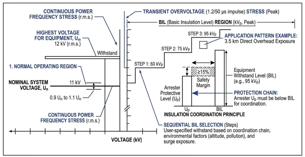
Basic Impulse Level (BIL) is the standardized benchmark for how much impulse voltage — a lightning strike or a switching transient — an accessory must withstand without flashover or puncture. It is expressed as a peak voltage figure (kVp) rather than an RMS operating value, since impulse events are short-duration transients, not steady-state stresses. A bushing rated for continuous service at 24 kV may carry a BIL rating of 125 kVp, reflecting that transient stresses can reach several times nominal voltage in a fraction of a millisecond.
Um, the highest system voltage, is distinct from nominal system voltage and represents the maximum voltage equipment must tolerate under normal operating conditions, including voltage rise during light-load periods. IEC-based systems typically define Um slightly above nominal — a 24 kV nominal system commonly carries an Um of around 24 kV to 25.8 kV — and accessory selection references Um, not the nominal figure, when confirming continuous voltage withstand.
The general coordination relationship can be expressed as: BIL ≥ k × Um × √2, where k is a coordination factor accounting for switching surge behavior and insulation type. This is a simplified conceptual relationship — actual BIL selection follows standardized voltage-class tables rather than a direct calculation in most commercial projects.
Worked Example: 15 kV Class System
On a 15 kV-class system with Um near 17.5 kV, IEC 60071-1 (Table 2, Range I) assigns a standard rated lightning impulse withstand voltage (BIL) of 75 kVp or 95 kVp to associated bushings and switchgear, with the higher value typically selected for outdoor or moderate-pollution installations. A field engineer confirming compatibility on a retrofit project should check the BIL figure directly against the coordination data sheet rather than assuming it from voltage class — mismatches between a legacy 95 kVp bushing and a replacement rated only to 75 kVp have shown up during commissioning impulse tests on more than one retrofit, well after procurement was finalized.
IEC 60071-1 governs the general principles of insulation coordination, including standardized values for BIL and rated withstand voltage referenced throughout this framework. IEC 60071-1 insulation coordination standard
The relationship between highest system voltage (Um), nominal rated voltage, and stepped Basic Impulse Level (BIL) values used in accessory coordination.
[Expert Insight]
BIL is a peak impulse value (kVp) — never confuse it with RMS operating voltage on a datasheet
Always confirm BIL against the coordination study, not the nameplate voltage class alone
Retrofit projects carry the highest mismatch risk, since legacy BIL ratings aren’t always documented on-site
Creepage Distance and Clearance — Two Different Failure Mechanisms
Clearance and creepage distance are two parameters insulation coordination relies on to govern how an accessory prevents flashover, but they address different physical failure paths and cannot substitute for one another. Treating a longer housing profile as automatically improving both is a common specification error that shows up in field contamination failures on otherwise well-rated equipment.
Clearance: Through-Air Strike Distance
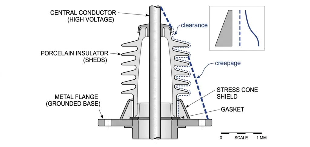
Clearance is the shortest distance through air between two conductive parts of opposite polarity or between a live part and ground. It governs resistance to breakdown through the air gap and is the parameter most directly tied to BIL. On MV bushings in the 15 kV to 35 kV class, clearance distances commonly fall in the 150 mm to 320 mm range depending on BIL rating and mounting configuration.
Creepage: Surface Leakage Path
Creepage distance is the shortest path along the surface of the insulating material between the same two conductive points. It governs resistance to surface tracking — a slower, contamination-driven mechanism where moisture and pollutants on the insulator surface create a conductive film that gradually carbonizes into a permanent leakage path. Creepage requirements are expressed as a ratio, typically 16 mm/kV to 31 mm/kV of Um, scaled upward for higher pollution classes rather than fixed to voltage class alone.
A useful field distinction: clearance failures tend to be sudden (a single overvoltage event bridges the air gap), while creepage failures are progressive — a surface tracked at 60% capacity during a wet-season inspection can fail completely within a single subsequent storm season if contamination isn’t addressed.
Field inspection teams have observed bushings with adequate clearance and BIL still develop tracking-related flashover because creepage distance was specified against a standard pollution assumption rather than actual site contamination — reinforcing that both parameters must be verified independently.
Cross-sectional view of a medium-voltage bushing illustrating the through-air clearance path versus the surface creepage path along the housing contour.
Pollution Class and Environmental Derating
Pollution class is the environmental variable that shapes insulation coordination requirements beyond voltage class alone, determining how much creepage distance an accessory needs beyond the baseline set by voltage class. It is one of the most under-specified parameters in accessory RFQs. Standard systems typically define four tiers — light, medium, heavy, and very heavy contamination — each assigning a different creepage ratio to the same voltage class.
Pollution Class I–II: Light to Moderate Exposure
Inland, low-humidity sites with minimal industrial activity generally fall into the light-to-moderate categories, where ratios around 16 mm/kV to 20 mm/kV of Um are typically adequate. A 24 kV Um bushing here might specify roughly 384 mm to 480 mm of total creepage distance.
Pollution Class III–IV: Heavy Industrial/Coastal Exposure
Coastal sites, cement or chemical plants, and heavy dust environments push into the heavy-to-very-heavy categories, where ratios climb to 25 mm/kV to 31 mm/kV or higher. On the same 24 kV Um bushing, this can raise required creepage to 600 mm to 744 mm — enough difference that a standard-catalog bushing selected without a site assessment will underperform within one to two wet seasons.
Field inspection experience on coastal substation retrofits has repeatedly shown that salt deposit accumulation combined with morning condensation accelerates tracking on bushings specified to an inland-default pollution class — a gap typically caught only at a scheduled maintenance walkdown revealing surface arcing marks. Site-specific environmental data, not catalog defaults, should drive pollution class selection; the accessory supplier can only build to the class specified, not infer it independently. For deeper guidance, see ZeeyiElec’s guide on MV bushings for coastal and polluted environments.
How Insulation Coordination Drives Accessory Selection by Voltage Class
Once the core insulation coordination parameters — BIL, creepage, and pollution class — are known, the practical task becomes matching each transformer accessory family’s rated values against those three parameters — not selecting on nominal voltage alone. A selection that satisfies voltage class but overlooks BIL or creepage margin will pass visual inspection and still fail under transient or contamination stress later.
Bushings (LV and MV)
MV bushings are the family most directly governed by these ratings, since BIL and creepage figures are usually standalone catalog parameters. A 12 kV to 52 kV MV bushing range typically spans BIL ratings from roughly 75 kVp to 250 kVp. LV bushings operate at 1.2 kV to 3.0 kV with comparatively low BIL requirements, since their concern shifts toward thermal management rather than transient withstand.
Loadbreak Switches and Tap Changers
Loadbreak switches in the 15/25 kV to 38/40.5 kV range and off-circuit tap changers in the 15 kV to 35 kV range both require BIL verification against the transformer’s coordination data, since these devices sit at accessible external interfaces where switching surges and contamination exposure apply simultaneously.
Fuses (Bay-O-Net and Current Limiting)
Bay-O-Net fuse assemblies, commonly rated 15/25 kV class with BIL around 150 kVp, and current limiting fuses spanning 15.5 kV to 40.5 kV classes, must coordinate with system BIL as well as with each other’s clearing characteristics.
Cable Accessories (Cold/Heat Shrink)
Cold and heat shrink cable accessories in the 8.7/15 kV to 26/35 kV range apply the same logic at the cable interface, where creepage along the stress cone geometry becomes the dominant parameter rather than clearance.
Selection rule of thumb: accessory BIL ≥ system-required BIL, and accessory creepage ≥ site-adjusted creepage minimum — both conditions must be satisfied independently; exceeding one does not compensate for a shortfall in the other.
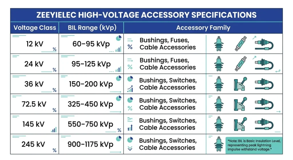
Selection matrix mapping voltage class to typical BIL range across bushings, switches, fuses, and cable accessories for coordinated procurement decisions.
Never select by voltage class label alone — cross-check BIL and creepage independently
LV bushing selection prioritizes thermal capacity over transient withstand
Cable termination creepage lives along the stress cone geometry, not a simple housing dimension
Altitude Correction and Site-Specific Adjustments
Altitude is the fourth variable insulation coordination must account for, since air density decreases with elevation, and clearance withstand depends on the dielectric strength of air — performance degrades at higher altitudes even when physical clearance stays unchanged. An accessory that performs correctly at sea level can carry a reduced effective BIL at elevation unless a correction factor is applied.
Standard practice commonly applies correction above approximately 1,000 m, with the derating factor increasing progressively — generally following an exponential rather than linear relationship.
A simplified working relationship: Ka = e(H − 1000)/8150, where H is installation altitude in meters and Ka is the correction factor applied to reduce effective withstand voltage. This is a commonly referenced approximation; project-specific coordination studies should confirm the applicable formula and threshold for the governing standard.
At 2,000 m, the correction factor typically reduces effective withstand by roughly 10% to 13% relative to sea-level rating, meaning an accessory rated 125 kVp BIL at sea level may deliver only around 110 kVp to 112 kVp of effective withstand at that altitude. Projects sited in mountainous or high-plateau regions — where elevations of 2,500 m to 3,500 m are not uncommon — have occasionally specified accessories using sea-level catalog BIL ratings without correction, an oversight that typically surfaces only during commissioning impulse testing or the first significant lightning season.
Correction factors and threshold elevations vary between standard bodies and even between product certifications, so site elevation should be confirmed against the manufacturer’s documented methodology before finalizing an order.
Verifying Coordination Requirements Before RFQ
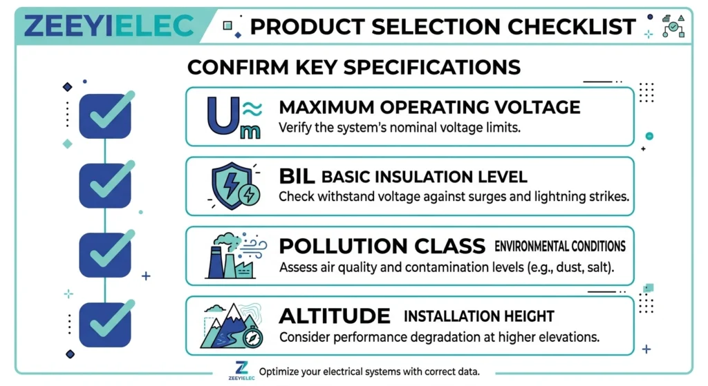
Before issuing an RFQ, four parameters should be confirmed rather than left to catalog defaults: highest system voltage (Um), required BIL, site pollution class, and installation altitude. Each shapes which bushing, switch, fuse, or cable accessory variant is suitable — specifying by nominal voltage class alone routinely produces mismatches that surface only at commissioning or later.
A working checklist for RFQ preparation:
Confirm Um from the transformer nameplate or system study, not just nominal voltage
Confirm required BIL from the coordination study, or standard voltage-class tables if none exists
Confirm site pollution class from environmental survey data (coastal, industrial, or inland)
Confirm installation altitude and whether correction factors apply above 1,000 m
Skipping any one of these typically doesn’t block manufacturing or shipment — it surfaces later, during impulse testing or commissioning, when correction costs considerably more than catching the gap at RFQ stage.
Four-point checklist for confirming Um, BIL, pollution class, and altitude before submitting a transformer or cable accessory RFQ
Frequently Asked Questions
What is insulation coordination in simple terms?
It is the process of selecting the dielectric withstand levels of all system components so they align with the maximum voltage stress the system can experience, typically referenced to standards such as IEC 60071, though exact levels depend on system design and site conditions.
What is the difference between BIL and rated voltage?
Rated voltage (or Um) describes the highest continuous system voltage a component must withstand, while BIL describes the transient impulse withstand level, usually several times higher, and the two are selected together rather than interchangeably.
Why does creepage distance matter more in polluted environments?
Creepage distance governs surface leakage current paths, and contamination combined with moisture in coastal or industrial sites can create conductive tracking paths well before the design voltage is reached, so higher pollution classes require longer creepage paths regardless of BIL.
Does altitude affect insulation coordination requirements?
Yes, reduced air density at higher elevations lowers the dielectric strength of air-gap clearances, so installations above roughly 1,000 m commonly require a correction factor applied to clearance and sometimes BIL selection, subject to the governing standard and project specification.
Can an accessory with higher BIL always be substituted for a lower-rated one?
In most cases a higher-BIL accessory can be substituted if dimensional and interface compatibility are confirmed, but the substitution should still be checked against mounting geometry and coordination with adjacent components rather than assumed automatically.
How is pollution class determined for a project site?
Pollution class is typically assessed from environmental survey data — proximity to coastline, industrial emissions, dust, and humidity patterns — and is usually specified by the project engineer or utility rather than left to the accessory supplier to assume.
yoyo shi
Yoyo Shi writes for ZeeyiElec, focusing on medium-voltage accessories, transformer components, and cable accessory solutions. Her articles cover product applications, technical basics, and sourcing insights for global electrical industry buyers.





 English
 한국어
한국어 العربية
 Español
 हिन्दी
 தமிழ்
தமிழ் Deutsch (Sie)
 Français
 Português do Brasil
 Русский