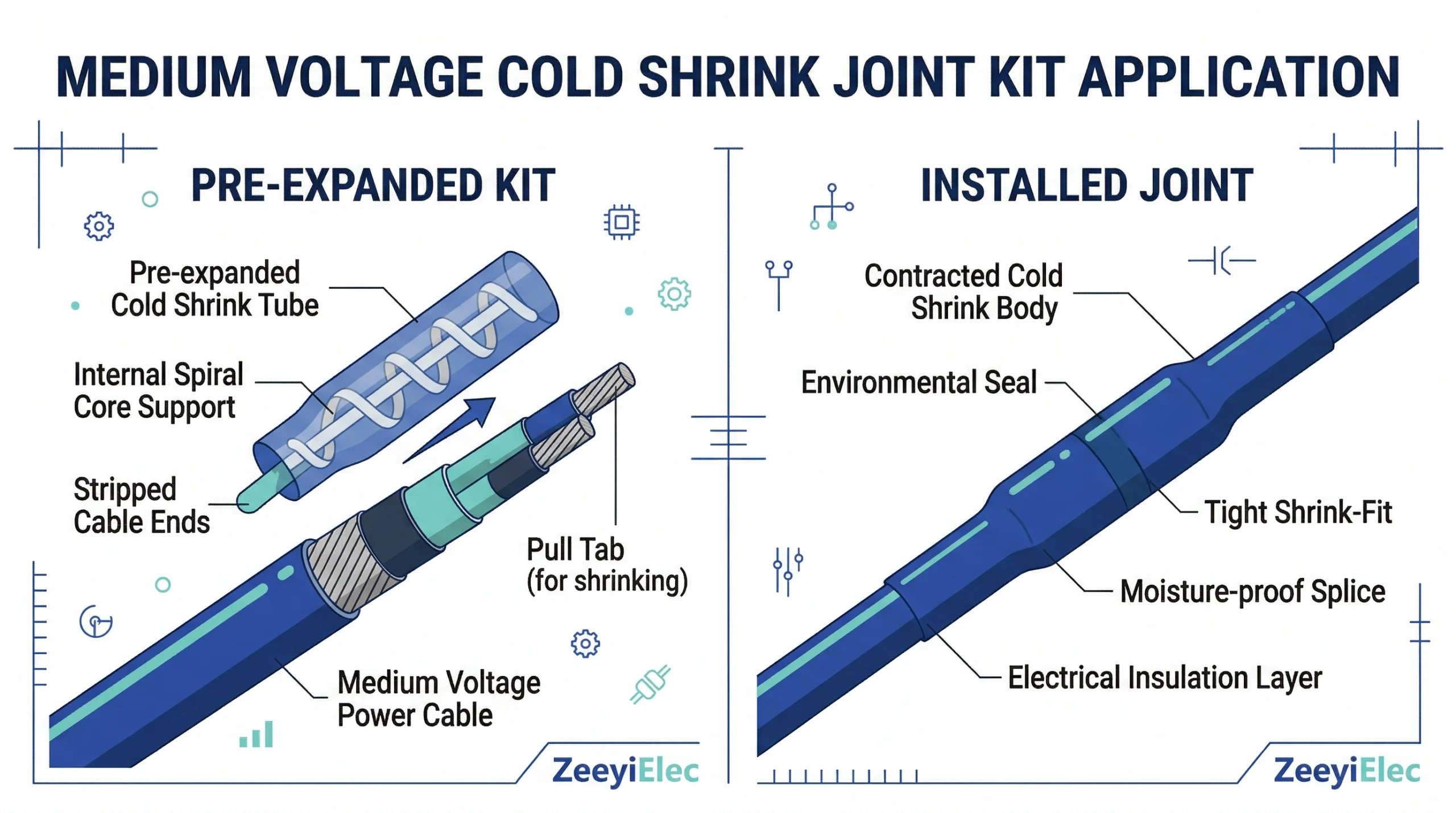
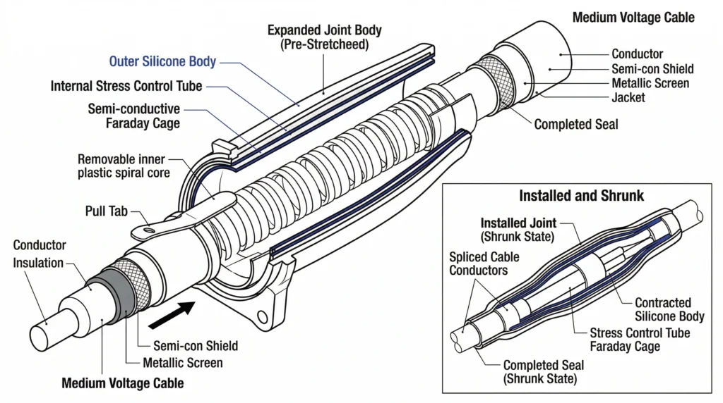
Cold shrink cable accessories are pre-expanded silicone insulation components used for medium-voltage cable terminations and joints. Unlike heat shrink technologies that require open flames to activate, cold shrink joints rely on the elastomeric memory of liquid silicone rubber (LSR) or Ethylene Propylene Diene Monomer (EPDM). They are factory-expanded over a removable plastic spiral core, which is manually unwound during installation to allow the rubber body to contract and form a tight, void-free seal over the prepared cable interface.
A cross-sectional view of a pre-expanded cold shrink joint detailing the primary silicone body, Faraday cage, and high-permittivity stress control layer.
The Principle of Elastomeric Memory
At the core of Zubehör für Kaltschrumpfkabel is the material’s structural ability to return to its original engineered dimensions after being stretched up to 300% of its resting diameter. During manufacturing, the silicone compound is injection-molded, cross-linked, and then mechanically expanded onto the support core. When the field technician pulls the core ribbon, the material aggressively collapses onto the cable insulation, dielectric screen, and jacket. This cold-applied mechanism eliminates the risk of scorching the primary insulation, a common field error when gas torches are improperly handled during heat shrink installations.
Active Radial Pressure Dynamics
A critical differentiator in the physics of cold shrink technology is the sustained active radial pressure it exerts throughout the accessory’s 25 to 40-year service life. As power distribution cables undergo thermal load cycling—heating up to ≥ 90°C during peak electrical demand and dropping to ambient temperatures off-peak—the physical dimensions of the cable insulation expand and contract. Heat shrink materials become rigid after cooling and cannot track these volumetric changes dynamically, which can potentially leave micro-voids at the interface. Cold shrink silicone, however, maintains a continuous radial pressure of approximately 0.08 to 0.15 MPa. This active tracking ensures the interface remains void-free, severely limiting the potential for partial discharge (PD) tracking or internal dielectric breakdown.
Pre-Expanded Structural Layers
Modern medium-voltage cold shrink joints are manufactured as all-in-one, multi-layered bodies. A single expanded unit typically houses the inner semi-conductive electrode (Faraday cage) to shield the mechanical connector, a high-permittivity geometric stress control layer to manage electrical fields at the screen cutback, and the primary weather-resistant silicone insulation. Consolidating these functional layers in the factory drastically reduces the number of steps required by the field installer, ultimately lowering the probability of human error, void formation, and moisture contamination during the jointing process.
[Experteneinblick]
Storage Temperature — Always store cold shrink kits below 40°C in climate-controlled environments to prevent premature relaxation of the elastomeric memory.
Core Removal Technique — Pull the spiral core ribbon counter-clockwise at a steady, continuous pace; jerking the ribbon can cause the silicone to snap down unevenly and trap air pockets against the dielectric.
Matching Joint Kits to Field Application Environments
Selecting the correct cold shrink joint extends beyond matching the electrical ratings; the operating environment dictates the required mechanical and environmental protections. A joint that performs flawlessly in a clean, climate-controlled switchgear room may fail prematurely if subjected to the harsh realities of an underground splice in a flooded duct bank. Field engineers must thoroughly evaluate the installation site to specify the correct outer sealing and physical protection layers for their Kabelzubehör.
When cold shrink joints are installed directly in the soil, they face continuous mechanical stress from backfill settling and thermal expansion. Standard direct burial installations typically occur at depths between 0.8 and 1.2 meters, where ground moisture is a constant threat. While the primary silicone body provides excellent dielectric strength, the joint kit must include a heavy-duty outer re-jacketing tube. In field applications with high rock content or heavy surface traffic, an external resin-filled shell is often specified over the cold shrink joint to absorb mechanical impacts and prevent point-loading on the splice.
Submersible and Vault Conditions
Manholes, utility vaults, and duct banks frequently flood, subjecting joints to continuous submersion. In these environments, the critical parameter is the water sealing integrity of the joint’s extremities. Submersible cold shrink joint kits utilize specially formulated water-blocking mastics at the cable jacket cutbacks. These seals must be capable of withstanding significant hydrostatic pressure, often tested to endure ≥ 3.0 meters of water head for extended periods without permitting moisture ingress into the metallic shield or conductor.
Cable Trays and Indoor Switchgear
For indoor and outdoor terminations and straight-through joints supporting 10kV and 35kV class distribution cable projects, space constraints and fire safety take precedence. Joints installed in cable trays or beneath switchgear often do not require the extreme mechanical armor of direct burial kits. Instead, the focus shifts to utilizing halogen-free, flame-retardant silicone materials. The compact profile of a standard cold shrink joint is highly advantageous here, allowing multiple splices to be racked closely together without violating the strict phase-to-phase and phase-to-ground clearance requirements of the switchgear cabinet.
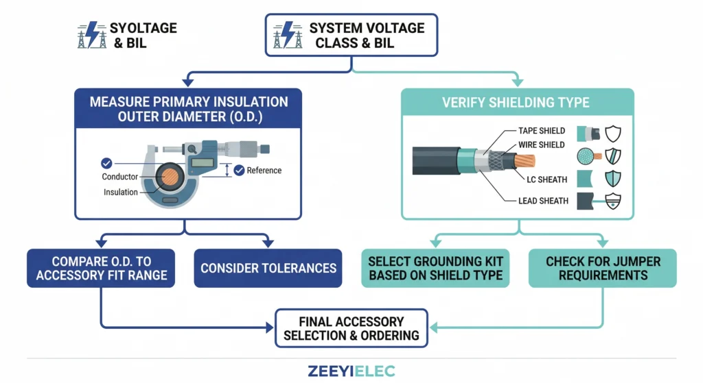
Step-by-Step Selection Logic for MV Cable Joints
Improper accessory selection accounts for approximately 35% of cable system failures within the first five years of operation. To prevent these premature dielectric breakdowns, engineers must follow a rigorous, parameter-driven specification process. Relying solely on the overarching voltage class often leads to dimensional mismatches that compromise the active radial pressure of the silicone body.
System voltage class establishes the baseline, but the primary dielectric outer diameter dictates the exact cold shrink kit range required.
Spannungsklasse und BIL-Werte
The primary selection criterion is the system’s operating voltage, typically expressed as U0/U (Um). For medium-voltage distribution networks, standard designations include 8.7/15 kV and 26/35 kV. However, the accessory must also meet the system’s Basic Insulation Level (BIL) to withstand transient overvoltages from lightning strikes or switching events. Engineers should verify that the joint’s continuous AC withstand voltage and impulse voltage ratings comply with [NEED AUTHORITY LINK SOURCE: IEC 60502-4 testing standards for medium voltage accessories] performance requirements for the specific network architecture.
Conductor Cross-Section and Range-Taking Capability
While cable specifications frequently center on the conductor cross-section (e.g., 50 mm² to 400 mm²), cold shrink joint selection relies fundamentally on the primary insulation’s outer diameter. Because the elastomeric silicone must maintain a continuous radial pressure of ≥ 0.08 MPa, the kit’s structural design inherently limits its application range. A joint designed for an insulation diameter of 17.5 mm to 33.0 mm will fail to seal properly if applied to a cable measuring 16.0 mm, leading to rapid moisture ingress and partial discharge. Installers must always measure the actual stripped insulation diameter over the dielectric rather than trusting nominal datasheet values.
Shielding and Grounding Compatibility
Medium-voltage cables utilize various metallic shielding configurations, primarily copper wire screens or copper tape shields. The joint kit must include the appropriate mechanical connectors, constant force springs, and tinned copper braids to restore this metallic continuity across the splice. The cross-sectional area of the provided grounding braid must be capable of carrying the network’s anticipated phase-to-ground fault current for the required duration (typically 1 second) without thermal degradation of the underlying silicone insulation. Failing to match the grounding kit to the specific cable shield type is a frequent cause of localized thermal faults at the joint interface.
[Experteneinblick]
Tolerance Margins — Never round down a cable’s measured insulation diameter; a 16.5 mm dielectric will not effectively seal in a joint rated for a 17.5 mm minimum, regardless of how tight it looks to the naked eye.
Shielding Match — If transitioning from copper tape to a copper wire screen, ensure the kit includes a constant force spring rated for the combined fault current geometry of both shield types.
Avoiding Sizing Mismatches and Installation Failures
Field data consistently shows that proper accessory selection accounts for only part of the reliability equation; execution during installation carries equal or greater weight. A 15 kV cold shrink component might pass all factory acceptance tests, yet still fail at month fourteen if field preparation protocols are ignored. Implementing a strict Checkliste für die Qualitätskontrolle bei der Installation von MV-Zubehör helps identify defects before energization, when correction remains practical and economical.
Field Failure Prevention Matrix
Installation Error
Electrical Consequence
Field Prevention Strategy
Undersized cable insulation
Insufficient radial pressure, moisture tracking
Caliper measure primary dielectric before kit selection
Scored primary insulation
High electrical stress concentration, rapid treeing
Use calibrated depth-stop stripping tools
Missing void-filling mastic
Air pockets leading to internal partial discharge
Apply high-permittivity mastic flush with screen step
Primary Insulation Diameter Mismatches
A frequent error occurs when procurement teams order joints based solely on nominal conductor size rather than the actual insulation diameter. If a cold shrink silicone body is applied to a cable diameter that falls below its minimum engineered shrink range, it cannot generate the ≥ 0.08 MPa of active radial pressure required to maintain a void-free interface. Without this pressure, thermal cycling creates micro-gaps, leading to corona discharge and eventual dielectric breakdown.
Improper Semi-Conductor Screen Cut-Backs
The transition point where the outer semi-conductive screen is removed is the area of highest electrical stress within the joint. Installers often use standard utility knives to score the semi-con, inadvertently cutting into the primary XLPE or EPR insulation.
Even microscopic scoring depths of ≤ 0.1 mm alter the equipotential lines, creating severe stress enhancements that standard stress control tubes cannot fully mitigate. Field experience dictates using calibrated, depth-restricted stripping tools or specialized glass scraping techniques to ensure a perfectly smooth transition without damaging the underlying dielectric.
Mastic Misapplication and Moisture Ingress
Cold shrink technology relies heavily on the correct application of accessory mastics at critical interfaces, particularly the connector region and the screen cut-back step. High-permittivity stress relief mastic must be stretched and wrapped to eliminate all air voids around the mechanical or compression connector. If an installer fails to build a smooth, tapered profile, the resulting trapped air pockets will ionize under medium-voltage stress, initiating partial discharge that physically erodes the silicone housing from the inside out.
International Standards and Testing Requirements
When specifying cold shrink joints for medium-voltage networks, relying on generic supplier claims is a direct path to premature failure. Incomplete specifications cause 30–40% of cable accessory site rejections. Procurement teams frequently inherit generic requirements, which means accessories arrive on site and problems surface during factory acceptance testing. Translating international standards into actionable procurement language prevents these specification gaps before they become project delays.
Type Testing and Factory Acceptance Testing
The International Electrotechnical Commission (IEC) develops standards defining minimum performance requirements, test methods, and acceptance criteria for power cable systems. For medium-voltage accessories, IEC 60502-4 and [VERIFY STANDARD: IEEE 404 for extruded dielectric cable joints] dictate the rigorous sequence of electrical, mechanical, and thermal trials a joint design must survive before commercial deployment.
A rigorous type testing sequence for a typical 24 kV cold shrink joint includes continuous AC voltage withstand testing, which subjects the assembled joint to 4.5 U0 (approximately 54 kV) for 5 minutes without dielectric puncture. Equally critical is the partial discharge (PD) assessment. To guarantee long-term insulation integrity and active radial pressure stability, the joint must exhibit a discharge magnitude of ≤ 10 pC when tested at 1.73 U0. These stringent thresholds verify that the factory-molded silicone body and internal stress control layers are free of microscopic voids before they ever reach the field.
Standardizing Procurement Specifications
Field engineers assume massive operational risk when authorizing the energization of a joint that lacks verified type test reports for the exact cable insulation material (such as XLPE or EPR) used on-site. To bridge the gap between engineering requirements and purchasing reality, referencing an IEC/Projektspezifikation Spickzettel für die Beschaffung von Zubehör is highly recommended. This documentation consolidates critical IEC parameters and testing requirements into one reference for professionals sourcing medium-voltage cable accessories.
By standardizing these requirements, buyers ensure that manufacturers supply comprehensive factory acceptance test (FAT) data with every batch, confirming that the delivered cold shrink joints match the exact electrical and dimensional tolerances proven during initial type testing.
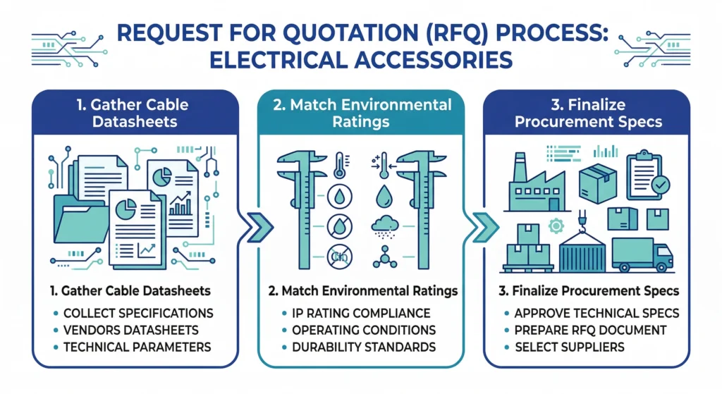
Specifying Cold Shrink Joints for Your Next Project
A missing data point in your Request for Quotation does not simply slow down procurement. It triggers a cascade of supplier clarification emails, engineering hunts for cable datasheets, and delayed quotation deadlines. Multiply this across six or eight line items on a substation project, and what should have been a two-week RFQ cycle easily stretches into six weeks. To prevent these delays, a systematic framework is required for specifying terminations, joints, and separable connectors.
A standardized RFQ workflow translates project specifications into actionable procurement data, preventing costly manufacturing delays.
Gathering Essential Cable Data
Whether you are procuring cold shrink solutions or heat shrink alternatives for your medium-voltage networks, precise data is paramount.
Always specify the exact system voltage class, the primary insulation diameter range (e.g., 17.5 mm to 33.0 mm), and the conductor cross-section (e.g., 50 mm² to 400 mm²). Relying on just one parameter guarantees an eventual dimensional mismatch.
Partnering with ZeeyiElec for Export Documentation and Supply
Shipping cable accessories across international borders involves more than booking freight. A missing test certificate can hold a container at port for weeks, and a wrong HS code classification leads to unexpected duty payments. We engineer reliable Transformatorenzubehör and cable accessories with complete export documentation support. Define every parameter your supplier needs to quote accurately and ensure seamless delivery.
Häufig gestellte Fragen
What is the shelf life of a cold shrink joint kit?
Cold shrink kits typically have a shelf life ranging from 12 to 24 months, depending heavily on storage temperature. Storing them in climate-controlled indoor environments prevents the pre-expanded silicone from losing its elastomeric memory or rupturing the plastic spiral core prematurely.
Can cold shrink joints be directly buried in soil?
Yes, most medium-voltage cold shrink joints are engineered for direct burial, provided they are installed with the manufacturer-specified environmental sealing mastics and heavy-wall outer protective tubes. Soil composition and ground moisture levels will dictate whether additional mechanical protection, such as a resin-filled outer shell, is required.
How do you size a cold shrink joint for transition splicing?
Sizing requires matching the joint kit’s application range strictly to the primary insulation diameter of both joined cables, rather than relying solely on the conductor cross-section. When transitioning between entirely different cable types (such as XLPE to PILC), highly specialized transition kits containing oil-barrier tubes and custom stress control elements must be specified.
Do cold shrink joints require special installation tools?
Unlike heat shrink alternatives, cold shrink joints do not require gas torches, hot air guns, or specialized hot-work permits. The installation relies entirely on the installer manually unwinding the inner plastic supporting core, allowing the silicone to contract naturally onto the cable profile.
What causes a cold shrink joint to fail after installation?
Premature field failures most frequently stem from improper cable preparation, such as scoring the primary insulation during semi-con screen removal or failing to properly apply void-filling stress control mastics. Additionally, sizing the joint too large for the specific cable’s insulation diameter results in insufficient radial pressure, inevitably leading to moisture ingress and partial discharge tracking.
Are cold shrink joints reusable once installed?
No, cold shrink joints are strictly single-use engineered components. Once the support core is extracted and the silicone body shrinks securely onto the cable, it cannot be safely re-expanded or removed without destroying the accessory’s insulation integrity.
Yo-Yo-Shi
Yoyo Shi schreibt für ZeeyiElec und konzentriert sich dabei auf Mittelspannungszubehör, Transformatorenkomponenten und Kabelzubehörlösungen. Ihre Artikel behandeln Produktanwendungen, technische Grundlagen und Einblicke in die Beschaffung für Einkäufer der globalen Elektroindustrie.