An LV bushing assembly typically combines a porcelain or cast-epoxy housing, a threaded terminal stud, and a compressed elastomer or fiber gasket at the flange where the bushing seats against the tank cover. The gasket—usually nitrile (NBR) or EPDM—is not a static barrier; it stays oil-tight only as long as it remains under continuous compressive load against both mating surfaces.
Flange bolts are generally torqued to 25–40 N·m (±10%) in a cross-pattern sequence to reach the gasket’s design compression set of 20–30% of its free-state thickness. Over-torquing by more than 15% frequently over-compresses the material beyond that window, which accelerates long-term compression relaxation rather than improving the seal.
In field inspections across low-voltage distribution transformer fleets, oil weeping around the LV bushing flange is typically the first visible fault indicator—it shows up well before winding-related problems register on dissolved gas analysis (DGA). Zeeyi’s low-voltage bushing product line is built around this compression tolerance, but the same failure logic applies to any gasketed LV bushing regardless of supplier.
Where Leaks Actually Originate: Four Common Failure Points
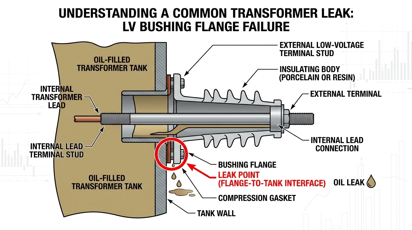
Cross-sectional view of an LV bushing assembly with the four common leak interfaces labeled: flange gasket, terminal stud seal, cement joint, and breather path.
Not every leak starts at the same location, and diagnosing the wrong point wastes a maintenance window. These are the four interfaces worth checking, in the order they typically fail.
Flange Gasket Interface
The primary compression seal between the bushing flange and the tank cover. This is the most common leak source and the easiest to inspect visually—oil tracking down the tank wall below the flange is the classic symptom.
Terminal Stud Seal
A secondary O-ring or gasket around the current-carrying stud where it passes through the bushing body. Leaks here are harder to spot because oil can travel along the stud before becoming visible at the top terminal.
Porcelain-to-Metal Cement Joint
On porcelain-housed bushings, the cement bond between the ceramic shell and its metal flange can crack under repeated thermal cycling, opening a slow seep path that gaskets alone can’t fix.
Conservator or Breather Path
On oil-filled units connected to a conservator, a compromised breather desiccant or a cracked sight-glass gasket lets moisture into the oil system, which shows up first as elevated moisture content near the bushing rather than as a visible drip.
[Expert Insight: Reading the Leak Pattern]
Oil at the flange base = gasket compression loss, not a bushing casting defect
Oil tracking along the stud only = terminal seal, check before replacing the whole bushing
Dry flange but rising moisture in oil tests = check the breather/conservator path first
Root Causes Behind Seal and Gasket Degradation
Line chart showing gasket compression set increasing over repeated thermal cycles, illustrating why seals loosen with transformer age.
Thermal Cycling and Compression Set
LV bushings on distribution transformers routinely cycle between ambient temperature and a hot-spot rise that can reach 65–80°C above ambient under load. Repeated expansion and contraction causes elastomer gaskets to lose elasticity—a phenomenon called compression set—so a gasket that sealed correctly at installation can no longer recover its shape after a few thousand thermal cycles.
Gasket Material Chemical Incompatibility
Nitrile gaskets swell and soften when exposed to certain synthetic ester or silicone-based transformer fluids, while EPDM is generally the better match for mineral-oil-filled units but performs poorly with petroleum-based cleaning solvents used during maintenance. [VERIFY STANDARD: manufacturer fluid-compatibility datasheet for the specific gasket compound in service] should confirm compatibility before any fluid change.
Installation Torque Errors
Under-torquing leaves the gasket below its design compression and the seal never forms properly; this is a leading cause of near-immediate leaks on newly commissioned transformers rather than a wear-related failure. Reference the bushing manufacturer’s torque specification (IEC 60137 is the relevant bushing standards framework for the broader bushing family, though LV-rated bushings often follow the transformer manufacturer’s own torque table) rather than a generic bolt-torque chart.
Surface Contamination During Assembly
Dust, old gasket residue, or handling oils left on the flange face during reassembly create micro-channels that a fresh gasket can’t fully close, even at correct torque. During bushing replacement projects in dusty or coastal installation environments, we’ve found that a degreased, dry-wiped flange face makes a measurably more consistent seal than skipping straight from gasket swap to bolt-up.
Field Diagnosis Checklist for Leaking or Failing LV Bushings
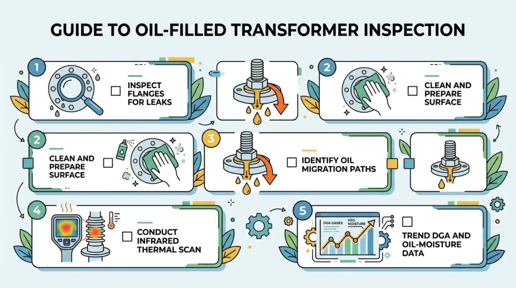
Five-step icon checklist for field-diagnosing an LV bushing leak, from visual inspection through DGA trend cross-check.
Visually inspect the flange-to-tank interface for oil tracking or a dark, tacky residue ring.
Wipe the area clean and re-inspect after 24–48 hours to distinguish an active leak from historical residue.
Check the terminal stud connection for oil migration along the conductor, which points to the secondary seal rather than the flange gasket.
Run an infrared scan of the bushing-to-tank joint; a differential of 8°C or more against an equivalent unhandled unit can indicate a partially compromised contact or seal.
Cross-check with the transformer’s oil moisture and DGA trend—rising moisture with no visible external leak usually means the breather or conservator path, not the bushing gasket itself.
[Expert Insight: Field Diagnosis Sequence]
Always distinguish “wet” (historical, already dried) from “weeping” (active) before scheduling a repair
A clean flange with rising oil moisture points away from the bushing gasket entirely
Document torque values at the last service interval—recurring leaks after re-torquing usually mean gasket replacement, not another torque pass
For a broader troubleshooting sequence covering other transformer accessories, Zeeyi’s field failure diagnosis workflow walks through the same wipe-and-recheck logic applied across bushings, tap changers, and loadbreak switches.
Gasket Material Comparison: EPDM vs Nitrile vs Silicone
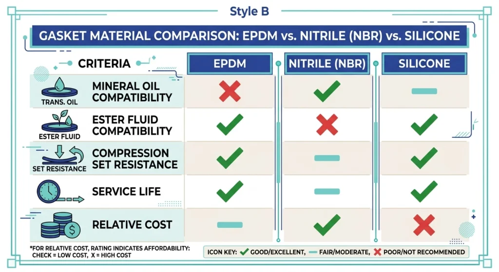
Flat infographic comparing EPDM, nitrile, and silicone gasket materials across fluid compatibility, compression set resistance, and service life.
Replacing a failed gasket is also a chance to reconsider whether the original material was the right fit for the operating fluid and environment.
Criterion
EPDM
Nitrile (NBR)
Silicone
Mineral oil compatibility
Good, standard choice
Excellent
Poor—swells over time
Ester/synthetic fluid compatibility
Poor
Fair to poor
Good
Compression set resistance
Good across wide temp range
Moderate, degrades faster >90°C
Excellent at temperature extremes
Typical service life (mineral oil, outdoor)
8–12 years
6–10 years
10–15 years, higher cost
Relative cost
Low
Lowest
Highest
For a standard mineral-oil-filled distribution transformer, EPDM or nitrile covers the large majority of applications; silicone is generally reserved for ester-filled units or extreme-temperature installations where the cost premium is justified.
Preventive Maintenance and Replace-vs-Repair Guidance
The most cost-effective point to intervene is before a gasket reaches full compression set, not after oil is visibly tracking down the tank. A practical rule: if a bushing has required re-torquing more than once for the same leak, replace the gasket rather than continuing to compensate with torque. Bundling gasket replacement with related cable-accessory maintenance—since cable termination seals follow a similar compression-based failure logic—often makes better use of a single outage window than treating each accessory separately.
If you’re sourcing replacement LV bushings or gaskets for a maintenance program, Zeeyi’s transformer accessories line covers bushings, tap changers, and Bay-O-Net fuse assemblies from a single supplier, which simplifies torque-spec and material-compatibility documentation across a fleet. Reach out with your voltage class and fluid type for a compatibility-checked recommendation.
Frequently Asked Questions
What does oil weeping at an LV bushing flange actually indicate?
It generally indicates the flange gasket has lost enough compression to stop sealing fully, most often from thermal cycling over several years or from under-torquing at the last service interval rather than a defect in the bushing casting itself.
How often should LV bushing gaskets be inspected?
Most utilities and industrial operators fold this into annual transformer maintenance, though units in high thermal-cycling service or humid coastal environments often warrant a mid-year visual check as well.
Can a leaking LV bushing be re-torqued instead of replaced?
A single re-torque is reasonable for a newly noticed, minor weep, but recurring leaks after re-torquing usually mean the gasket has taken a permanent compression set and needs replacing rather than further tightening.
Is a leaking LV bushing safe to leave in service short-term?
A minor, monitored weep with stable oil levels is typically manageable for a scheduled outage window, but any leak paired with rising moisture readings or visible tracking near the terminal should be treated as higher priority.
What’s the difference between LV and MV bushing sealing requirements?
MV bushings generally carry tighter dielectric and creepage requirements due to higher voltage stress, while LV bushing sealing is driven more by mechanical compression and fluid compatibility than by insulation coordination—see this LV vs MV bushing selection guide for the full decision framework.
Does gasket material affect bushing lifespan more than installation quality?
Both matter, but field data consistently shows installation torque errors cause earlier failures than material choice alone—a correctly torqued nitrile gasket in a compatible fluid will usually outlast an incorrectly torqued premium silicone gasket.
yoyo shi
Yoyo Shi writes for ZeeyiElec, focusing on medium-voltage accessories, transformer components, and cable accessory solutions. Her articles cover product applications, technical basics, and sourcing insights for global electrical industry buyers.






 English
 한국어
한국어 العربية
 Español
 हिन्दी
 தமிழ்
தமிழ் Deutsch (Sie)
 Français
 Português do Brasil
 Русский