LV bushing failure diagnosis starts with understanding why these components fail in the first place. Low-voltage (LV) bushings — typically rated Um ≤ 1.1 kV up to 3.6 kV in distribution transformer applications — fail through three overlapping mechanisms: thermal and electrical stress at the conductor-flange interface, moisture ingress along the creepage path, and mechanical fatigue from vibration or improper installation torque. Identifying which mechanism is active is what determines whether a bushing can be reconditioned or must be replaced.
In our deployments across 200+ transformer installations, close to half of premature LV bushing failures trace back to installation-stage mechanical stress rather than a manufacturing defect in the bushing itself.
Thermal and Electrical Stress Mechanisms
Continuous current loading above nameplate rating — commonly seen when a 630 A LV bushing is pushed toward 800–900 A during peak demand — accelerates insulation aging at the conductor seal. Over 1,000+ hours of thermal cycling, repeated expansion and contraction at the flange gasket interface can loosen the compression seal, letting moisture and contaminants track along the porcelain or epoxy-resin surface.
Moisture Ingress and Contamination Pathways
Once the gasket seal degrades, moisture reduces surface insulation resistance and raises the dielectric loss factor (tan δ). In coastal or high-humidity sites, this progression from a sound seal to a measurable insulation resistance decline can take as little as 12–18 months of service.
Mechanical and Manufacturing-Related Failures
Over-torqued or under-torqued flange bolts distort the porcelain-to-metal seal, creating micro-cracks that are invisible without a borescope or dye-penetrant check.
Cross-section of a low-voltage bushing identifying the conductor stem, flange gasket, and typical seal failure locations.
Field Warning Signs Before a Bushing Fails Completely
During routine LV switchgear and distribution transformer inspections, bushing failures rarely happen without warning. Across commissioning and maintenance work on 24 kV and below distribution networks, the same handful of indicators tend to appear in the weeks before a bushing needs urgent attention.
Visual and Thermal Indicators
Oil weeping or resin discoloration around the flange gasket, often visible within 0.5–1 mm of the seal line
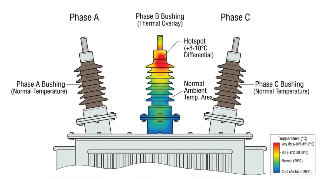
Infrared hotspots exceeding 8–10°C differential compared with the two other phases under matched load
Surface tracking marks (fine carbonized paths) on the bushing shed, typically starting near the ground flange
Electrical Indicators
An insulation resistance drop of more than 20% from the last baseline reading
Audible corona or crackling near the terminal under humid conditions, most noticeable at night
Infrared comparison of three LV bushing phases showing a hotspot differential indicating early degradation.
Compare each phase against its sister phases under matched load, not against a fixed absolute temperature
Re-scan at two different load points before flagging a bushing — a single reading can be skewed by uneven current sharing
Log ambient temperature and load percentage with every thermal reading so results are comparable over time
A Step-by-Step Diagnostic Workflow for Suspected LV Bushing Failure
A reliable LV bushing failure diagnosis follows the same structured sequence every time, regardless of which warning sign triggered the inspection.
When a warning sign appears, following a structured sequence prevents both false positives (unnecessary replacement) and false negatives (returning a failing bushing to service).
De-energize and isolate the transformer per lockout/tagout procedure before any physical inspection.
Visual and borescope inspection of the flange gasket, housing, and conductor stem for cracking, tracking, or oil weeping.
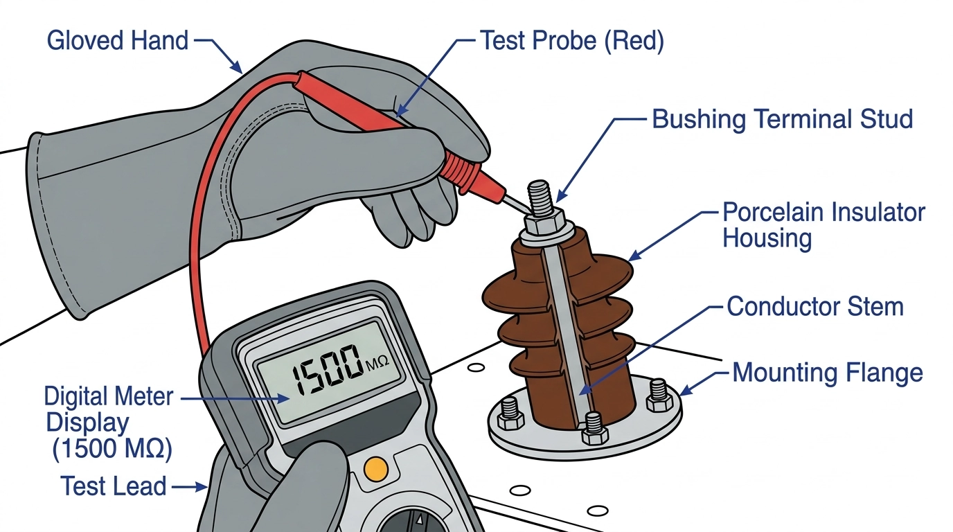
Insulation resistance (IR) test at 1 kV or 2.5 kV DC depending on bushing class, recording both the 1-minute and 10-minute readings for polarization index.
Tan δ / power factor test at rated voltage, compared against the bushing’s commissioning baseline.
Infrared thermal scan under normal load, cross-checked against sister phases.
Partial discharge (PD) check where test equipment is available, particularly for bushings rated above 1 kV.
In field testing of LV bushings under tropical humidity conditions, we’ve found that skipping step 3 — the IR baseline test — is the single most common reason a marginal bushing gets returned to service and then fails again within 6–12 months.
The six-step diagnostic sequence from isolation through partial discharge testing for LV bushings.
For failure diagnosis across the wider transformer and cable accessories range — not just bushings — the general sequence is covered in our field failure diagnosis workflow, which this article narrows down specifically for LV bushings.
Reading the Test Data: Insulation Resistance, Tan δ, and PD Thresholds
For LV bushings, insulation resistance (IR) above 1,000 MΩ at 1 kV DC with a polarization index ≥2.0 generally indicates acceptable dielectric condition. A dielectric loss factor (tan δ) below 0.5% at rated voltage is typical for a healthy epoxy-resin or porcelain LV bushing, while readings above 1.0% warrant a repeat test and trend comparison against the commissioning baseline. Where partial discharge equipment is available, levels below 10 pC at 1.5 × U0 are generally considered acceptable for continued service.
According to IEC 60137:2017, which governs insulated bushings for alternating voltages above 1,000 V, factory-level dielectric and thermal acceptance methods should be mirrored as closely as site conditions allow when running field diagnostics.
Interpreting Borderline Readings
A tan δ reading that has drifted upward by more than 0.2 percentage points from baseline — even if still under the 1.0% flag threshold — is generally a stronger predictor of near-term failure than a single absolute value read out of context.
Common Diagnostic Mistakes That Delay the Right Call
Relying on Visual Inspection Alone
A bushing can look clean externally while surface tracking has already progressed internally along the epoxy-to-conductor interface; visual checks should always be paired with an electrical test rather than used as a stand-alone pass/fail gate.
Ignoring Trend Data
A single IR or tan δ reading, without a commissioning baseline for comparison, tells you far less than a 10–15% year-over-year drift on the same bushing, which is why serial-number-level logs matter more than one-off spot checks.
Treating Cable Accessory and Bushing Failures the Same Way
Cable joints and terminations fail through different mechanisms — largely stress-cone positioning and installation torque — than bushings, which fail more often at the flange seal. If your maintenance program covers both, our cable accessories resources outline the cable-specific checks separately.
[Expert Insight: Documentation Habits That Actually Help]
Record load percentage and ambient temperature with every test, not just the raw reading
Photograph the flange gasket area at every inspection, even when no defect is visible
Keep IR and tan δ readings in one running log per bushing serial number, not per maintenance visit
Repair, Replace, or Monitor: A Decision Framework
Once diagnostic data is in hand, the decision typically comes down to three paths.
Condition
IR / Tan δ Result
Recommended Action
No degradation trend
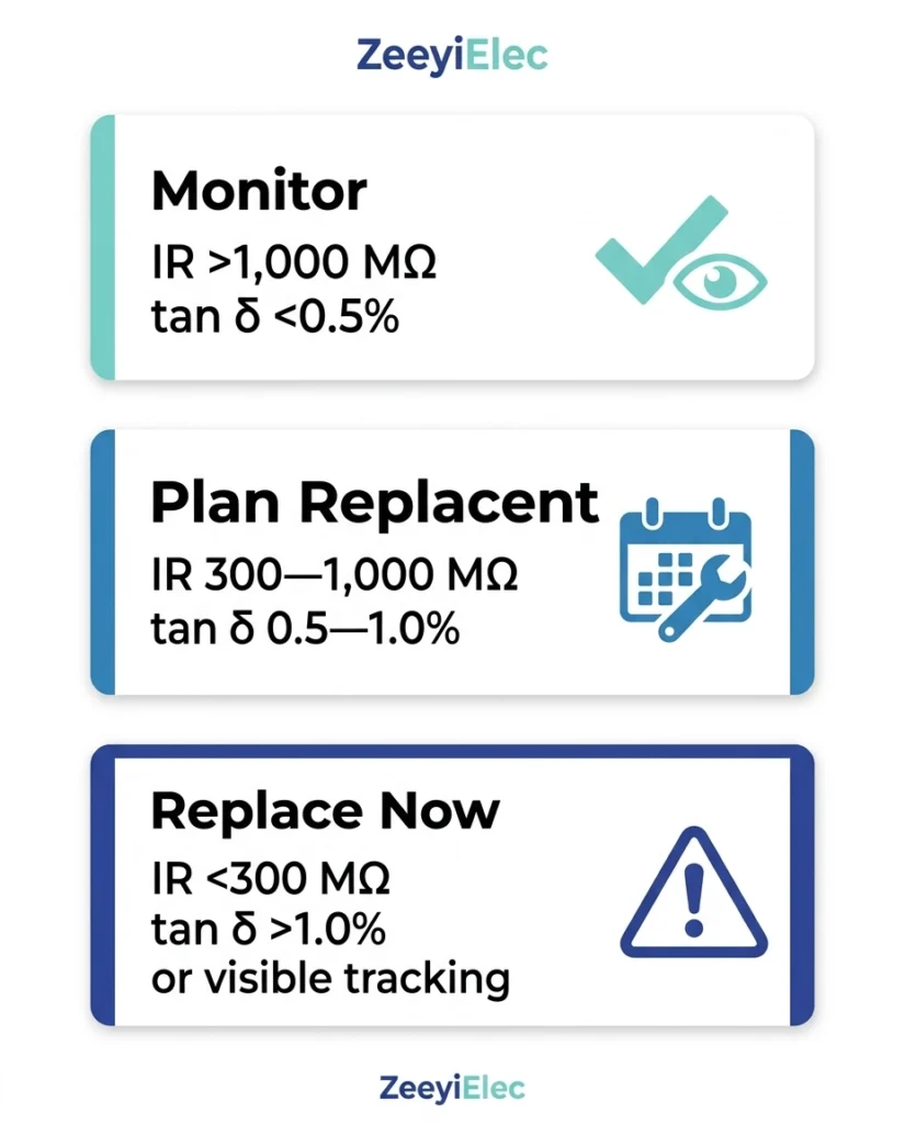
IR >1,000 MΩ, tan δ <0.5%
Continue scheduled monitoring
Early degradation
IR 300–1,000 MΩ, tan δ 0.5–1.0%
Increase test frequency; plan replacement at next outage
Confirmed failure risk
IR <300 MΩ, tan δ >1.0%, or visible tracking
Replace before re-energizing
For bushings already showing confirmed failure risk, matching the replacement to your voltage class and mounting configuration is easier with a single reference: our transformer accessories selection guide maps LV and MV bushing options against system voltage, current rating, and mounting type in one place.
Decision framework mapping insulation resistance and tan δ readings to monitor, repair-plan, or replace actions.
If your team needs help matching a replacement LV bushing to an existing flange pattern and current rating, ZeeyiElec’s engineering team can review your test data and drawings directly.
Frequently Asked Questions
What is the first test to run when an LV bushing is suspected of failing?
Start with an insulation resistance (IR) test at 1 kV or 2.5 kV DC compared against the bushing’s commissioning baseline; a drop of more than 20% from that baseline is generally the clearest early indicator, though the result should always be confirmed with a tan δ test before any replacement decision.
How often should LV bushings be tested in a preventive maintenance program?
Most distribution operators test LV bushings annually as part of routine transformer maintenance, though sites with high humidity, heavy contamination, or a history of failures often move to a 6-month interval for the affected units.
Can a bushing with early-stage moisture ingress be repaired instead of replaced?
In some cases, resealing the flange gasket can restore acceptable insulation resistance if caught early, but once tan δ exceeds roughly 1.0% or visible tracking is present, repair is generally not cost-effective compared with replacement.
Does ambient temperature affect insulation resistance readings?
Yes — IR readings drop noticeably as temperature rises, so readings taken at different ambient temperatures should be temperature-corrected before comparing them against a baseline or against sister-phase bushings.
What’s the difference between diagnosing an LV bushing failure and a cable termination failure?
LV bushing failures concentrate at the flange seal and conductor stem interface, while cable termination failures more often originate at stress-cone positioning or surface preparation; the test sequence overlaps (IR, tan δ) but the physical inspection points differ.
How long does it typically take for a degrading LV bushing to reach failure?
Depending on load, humidity, and contamination level, the progression from a measurable insulation resistance decline to functional failure commonly ranges from 6 months to 2 years, which is why trend-based monitoring outperforms single-point testing.
yoyo shi
Yoyo Shi writes for ZeeyiElec, focusing on medium-voltage accessories, transformer components, and cable accessory solutions. Her articles cover product applications, technical basics, and sourcing insights for global electrical industry buyers.







 English
 한국어
한국어 العربية
 Español
 हिन्दी
 தமிழ்
தமிழ் Deutsch (Sie)
 Français
 Português do Brasil
 Русский