What Determines Whether an MV Bushing Can Be Repaired or Replaced
Internal vs External Fault Boundary
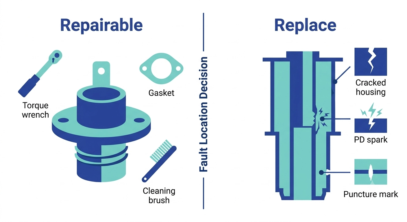
The decision to replace vs repair MV bushing faults comes down to a single factor: fault location, not fault severity. A bushing has two structurally distinct zones: the external interface (terminal stud, mounting flange, gasket seal) and the internal dielectric system (the central conductor, the insulating body, and the oil-to-air transition). External-zone faults are mechanical or environmental in nature and are generally correctable through cleaning, reseating, or hardware replacement. Internal-zone faults involve the dielectric material itself and are, in practice, not field-correctable — the insulation system was engineered and cured as a single unit, and no field process restores its original dielectric integrity once compromised.
This boundary matters because both fault categories can present with visually similar symptoms during a walkdown: discoloration, oil weeping, or surface arcing marks can originate from either a loose terminal connection or a degrading internal insulation path. Relying on surface appearance alone leads to misdiagnosis in both directions — unnecessary replacement of a bushing with a correctable terminal fault, or a “successful” repair that leaves an internal dielectric problem unresolved and progressing toward failure.
Why Fault Location, Not Fault Symptom, Drives the Decision
A medium-voltage bushing in the 12 kV–52 kV class is designed around a defined Basic Impulse Level (BIL) and a creepage distance sized to its pollution class; these parameters are fixed at manufacture and cannot be restored or upgraded through field repair. Once contamination, mechanical impact, or thermal cycling has degraded the internal creepage path or punctured the dielectric body, the unit no longer meets its original insulation coordination margin, regardless of how the exterior is cleaned or reworked.
In field experience, roughly 60%–70% of bushing-related service calls trace back to the external interface rather than the internal insulation system — a distribution that makes the diagnostic step covered later in this guide more consequential than the repair-or-replace decision itself. A bushing rated for 25 kV installed on a system requiring 35 kV insulation coordination will pass initial energization but risks flashover under transient overvoltage, which illustrates why IEC insulation coordination requirements for bushings — not visual condition — is the governing parameter engineers verify before authorizing any repair path.
For teams weighing this decision against a fuller product range, ZeeyiElec’s transformer accessories selection guide covers how bushings fit into the broader accessory system.
Repairable Fault Types: Terminal, Surface, and Interface Issues
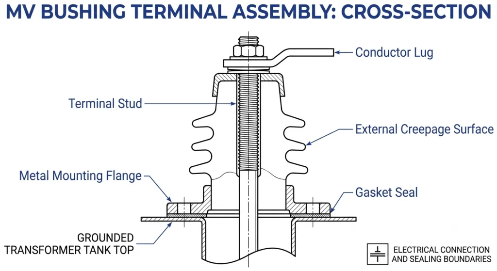
Bushing terminal interface cross-section identifying the three externally repairable fault zones: terminal connection, creepage surface, and sealing gasket.
Field experience across coastal and industrial distribution sites shows that most correctable bushing faults cluster into three categories, all located at the external interface rather than within the dielectric body.
Terminal Connection Faults
A terminal connection fault originates at the bolted or clamped interface between the bushing’s terminal stud and the external conductor lug — not within the internal insulation system. These faults typically present as localized heat discoloration or minor arcing marks at the connection point, driven by inadequate torque, conductor creep, or surface oxidation at the mating faces. Correction usually involves disassembly, cleaning of the contact surfaces, and reseating at the manufacturer’s specified torque value, commonly in the 40 N·m–80 N·m range depending on stud diameter and bushing current rating. Because the fault never crosses into the bushing’s dielectric path, a properly executed reseat restores full function without affecting the unit’s rated performance. A closer look at these failure patterns is covered in MV bushing terminal connection errors and rework prevention.
Surface Contamination and Early-Stage Tracking
Surface contamination interacting with humidity can create a partially conductive path across the bushing’s external creepage surface — the first stage of electrical tracking. At this early stage, before carbonization has formed a permanent path, the fault is generally correctable through cleaning with approved solvents and re-inspection of the creepage profile. Field teams distinguish early-stage tracking from progressed tracking by checking for a whitish, non-conductive residue (correctable) versus a visible carbonized black trail (not correctable). Waiting too long to intervene narrows this window: what begins as a cleaning task can progress to irreversible carbonization within months under sustained high-pollution exposure.
Gasket and Sealing Interface Degradation
The elastomeric seal at the mounting flange — typically EPDM or silicone rubber — is a wear component, not a permanent structural member. UV exposure and thermal cycling gradually reduce its compression set, allowing minor moisture ingress at the flange interface without necessarily compromising the internal dielectric. Replacing the gasket and re-torquing the flange in stages, rather than in a single pass, is standard field practice for restoring the seal without over-stressing the mounting interface.
[Expert Insight]
Terminal faults account for the majority of “bushing failure” calls that turn out not to require replacement.
Whitish residue vs. carbonized black trail is the fastest field test for tracking stage.
Gasket compression set is progressive — inspect on every scheduled outage, not just after a leak is reported.
Non-Repairable Fault Types: Internal Dielectric and Structural Failures
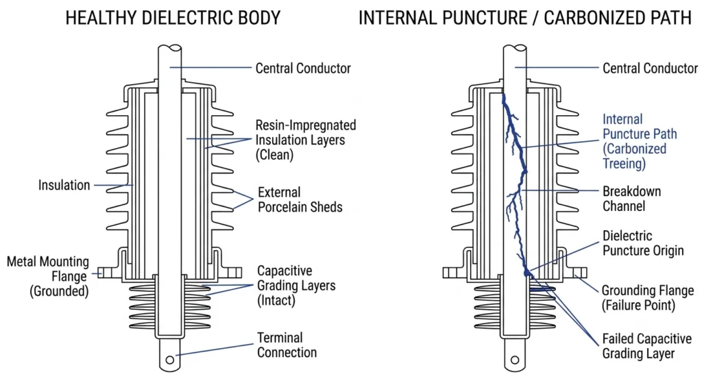
Side-by-side cross-section comparing a sound internal dielectric body to one showing puncture damage and carbonized tracking, illustrating non-repairable fault conditions.
Once a fault crosses from the external interface into the bushing’s internal dielectric system, field repair is no longer a viable option. These fault types share a common trait: they compromise the insulation system that was formed and cured as a single unit at manufacture, and no field process can restore that structure to its original performance.
Internal Dielectric Puncture
An internal dielectric puncture occurs when a localized electrical breakdown path forms through the bushing’s insulating body rather than across its external surface. This typically results from a manufacturing void, prolonged partial discharge activity, or a transient overvoltage event exceeding the unit’s Basic Impulse Level. A bushing rated at 125 kV BIL that experiences a transient surge substantially above that threshold can sustain internal puncture damage even without producing visible external symptoms — part of why insulation resistance and partial discharge testing matter more than visual inspection alone. Once punctured, the insulation path is permanently compromised and the unit must be replaced.
Cracked Porcelain or Epoxy Housing
A cracked housing — whether glazed porcelain or cast epoxy — breaches the sealed boundary between the internal dielectric fluid or solid insulation and the outside environment. Porcelain units are vulnerable to impact cracking during handling or transport, while cast epoxy bodies can develop stress cracks from repeated thermal cycling beyond their rated thermal class. In either case, no field coating, sealant, or resin patch restores the structural and dielectric integrity the housing is responsible for; the crack becomes a moisture ingress point that accelerates tracking and eventual flashover.
Progressive Partial Discharge Damage
Partial discharge (PD) activity below roughly 10 pC–50 pC in a healthy bushing is often within acceptable background levels, but PD magnitudes climbing above this range over successive test cycles indicate progressive internal degradation rather than a stable condition. Unlike a puncture or crack, PD damage develops incrementally — each discharge event erodes a small amount of insulation material, and the process accelerates once a conductive channel begins to form. CIGRE technical brochures on bushing condition monitoring note that a rising PD trend across repeat measurements is a stronger replacement indicator than any single absolute reading.
Field Diagnosis Workflow: Confirming Repair Eligibility Before Committing
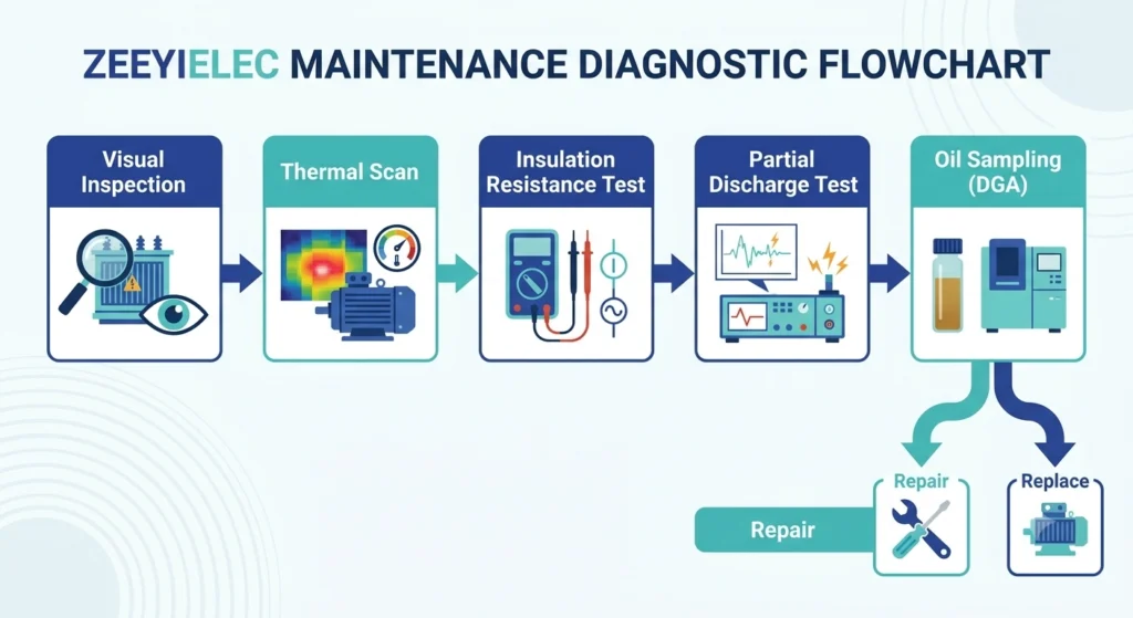
Field diagnostic sequence for MV bushings, from visual and thermal inspection through insulation resistance, partial discharge, and oil sampling tests.
Before committing to either a repair or a replacement order, field teams follow a structured sequence to confirm which zone — external interface or internal dielectric — actually contains the fault. Skipping steps in this sequence is the most common cause of misdiagnosis, where a terminal issue gets treated as a full bushing failure or, more dangerously, an internal fault gets dismissed after a surface cleaning. This mirrors the broader field failure diagnosis workflow used across transformer and cable accessories.
Visual and Thermal Inspection
The first pass is a visual walkdown checking for discoloration, oil weeping at the flange, chalking or tracking on the creepage surface, and any visible cracking in the housing. Paired with an infrared thermal scan under normal load, this step identifies hot spots at the terminal connection — commonly 15°C–25°C above ambient baseline on a sound joint versus a marked excess on a degrading connection — which points toward an external, repairable fault before any disassembly begins.
Insulation Resistance and Partial Discharge Testing
If the visual and thermal pass doesn’t clearly isolate the fault, insulation resistance (IR) testing and partial discharge (PD) measurement determine whether the internal dielectric is involved. An IR reading substantially below the unit’s baseline commissioning value — or a PD trend climbing across repeat tests — confirms an internal fault and rules out repair. These tests are typically performed with the bushing de-energized and, where feasible, compared against the original factory routine test values recorded on the nameplate or test certificate.
Oil and Contamination Sampling (Oil-Filled Applications)
For oil-immersed bushings, a dissolved gas analysis (DGA) sample from the surrounding transformer oil can reveal whether thermal or electrical fault byproducts are present, corroborating or ruling out internal bushing involvement versus a fault elsewhere in the tank. Elevated acetylene or hydrogen levels in a DGA result, taken alongside a positive PD trend on the specific bushing, moves the diagnosis firmly into replace-mandatory territory rather than a candidate for terminal or gasket repair.
Only after this sequence converges on a single fault zone should the decision proceed to the cost and downtime evaluation below.
[Expert Insight]
Never authorize replacement based on visual inspection alone — confirm with IR/PD data first.
Thermal scans catch terminal faults early, before discoloration is visible to the naked eye.
DGA correlation with PD trend is the strongest combined signal for internal fault confirmation.
Cost, Downtime, and Risk: Building the Decision Matrix
Once the diagnostic workflow has confirmed which zone contains the fault, the replace vs repair MV bushing decision shifts to weighing cost, downtime, and risk against each other. This is rarely a simple price comparison — a lower repair cost can still be the wrong choice if it carries a meaningfully higher risk of near-term recurrence.
Outage Window and Lead-Time Tradeoffs
A terminal or gasket repair can typically be completed within a scheduled 4-hour–6-hour outage window using components already on hand or sourced locally, while a full bushing replacement often depends on manufacturing or freight lead time that can extend well beyond a single planned maintenance window — particularly for less common voltage classes or BIL ratings. Utilities that schedule replacements reactively, only after a confirmed internal fault, frequently find the transformer sitting on an extended outage while the replacement unit is sourced, which is why many operators keep a small buffer stock of critical bushing ratings for their fleet rather than ordering on demand.
Repair Cost vs Replacement Cost Thresholds
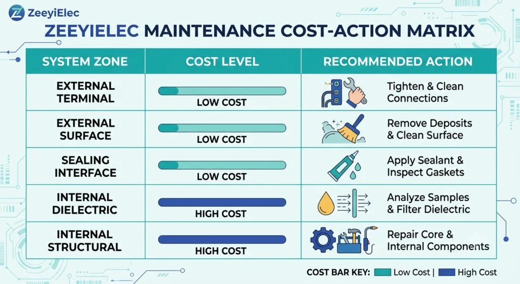
Decision matrix mapping bushing fault zone to typical finding, recommended action, and relative cost, from low-cost terminal repair to high-cost full replacement.
Replace vs Repair Decision Matrix
Fault Zone
Typical Finding
Recommended Action
Relative Cost
External terminal
Localized heat rise 15°C–25°C above baseline, no IR drop
Reseat at specified torque
Low
External surface
Early-stage tracking, non-conductive residue
Clean and re-inspect
Low
Sealing interface
Gasket compression set, minor moisture ingress
Replace gasket, stage torque
Low–Moderate
Internal dielectric
IR below baseline or PD trend rising
Replace bushing
High
Internal structural
Cracked housing or confirmed puncture
Replace bushing
High
As a rough field benchmark, a terminal or gasket repair typically runs at 5%–15% of the cost of a full bushing replacement once freight and installation labor for the new unit are included — but that comparison only holds when the diagnostic workflow has genuinely ruled out internal dielectric involvement. Treating an unconfirmed internal fault as repairable to save the 85%–95% cost differential risks a repeat failure that forces an unplanned, emergency-priced replacement later, at a premium well above the original planned cost.
When a “Working” Repair Still Carries Long-Term Risk
Not every replace vs repair MV bushing decision ends cleanly once a repair passes post-work testing. A repair that passes post-work testing and returns the bushing to service is not automatically a closed issue. Some fault types recur even after a technically correct repair, and recognizing this pattern is part of what separates a durable fix from a temporary one.
Repeat-Failure Patterns After Marginal Repairs
Terminal connections that have been reworked two or more times within a 12-month–18-month window on the same bushing point to a root cause beyond simple torque loss — commonly underlying conductor fatigue, a mismatched lug material causing galvanic corrosion, or a marginal internal condition that keeps stressing the external joint. Continuing to reseat the same connection without investigating why it keeps loosening treats the symptom rather than the cause, and each rework cycle also carries its own small risk of introducing a new fault at the reopened interface. When a terminal fault repeats on the same unit after a properly torqued repair, that recurrence itself becomes diagnostic evidence worth escalating to the IR/PD testing sequence described earlier, even if thermal scans still look acceptable.
Documentation Gaps That Mask Recurring Faults
A repair performed without recording the specific fault type, the torque value applied, and before/after test results leaves the next field team unable to distinguish a one-time correctable event from a developing pattern. Without that history, a bushing that has already had three terminal reworks over two years can be treated as a fresh, isolated fault each time — delaying the point at which someone recognizes the unit should be scheduled for replacement rather than repaired a fourth time. Maintaining even a simple per-unit log — fault date, symptom, corrective action, retest values — turns disconnected service calls into a visible trend line that supports a timely replace decision.
Sourcing Replacement Bushings and Verifying Compatibility
Once a replace vs repair MV bushing diagnosis confirms replacement is the correct path, compatibility verification prevents a second round of delay. The replacement unit must match not just voltage class but the full interface profile of the unit it’s replacing.
Matching Voltage Class, BIL, and Interface Dimensions
Confirming voltage class alone is not sufficient — a replacement bushing must also match the original’s Basic Impulse Level, current rating, and mounting flange dimensions. A unit rated correctly for 25 kV but sourced with a mismatched flange bolt pattern or terminal thread size will stall installation on site even after freight and lead time have already been absorbed. Cross-referencing the original nameplate data against the replacement’s technical datasheet, rather than relying on voltage class alone, is the step that prevents this mismatch.
RFQ Data Points Suppliers Need
A complete replacement RFQ should specify voltage class, BIL, current rating, standard system (ANSI or DIN), creepage distance or pollution class, and terminal configuration — incomplete specifications are a common cause of quotation delays and mismatched shipments.
ZeeyiElec supplies medium-voltage bushings across its transformer accessories product line, alongside cable accessories for the connecting cable systems, in ANSI, DIN, and epoxy configurations, with technical review support for matching replacement units to existing installation interfaces. Share nameplate data and site conditions for a compatibility check and quotation.
Frequently Asked Questions
Field teams evaluating replace vs repair MV bushing options should start with service-life expectations.
How long does an MV bushing typically last before repair or replacement is needed?
Service life commonly runs 25–40 years under normal loading and contamination levels, but coastal, industrial, or high-pollution sites can shorten this considerably depending on maintenance frequency and material grade.
Can a cracked bushing housing ever be repaired instead of replaced?
Generally no — a cracked porcelain or epoxy housing compromises the sealed dielectric boundary, and field sealants or coatings cannot restore the internal insulation integrity that the housing is structurally responsible for.
What is the most common repairable MV bushing fault in the field?
Terminal connection faults from under-torqued or corroded bolted joints are among the most frequent repairable issues, since the fault sits at the external interface rather than within the bushing’s internal insulation.
How is internal dielectric failure diagnosed before deciding to replace a bushing?
Insulation resistance testing and partial discharge measurement are the primary field methods, often supplemented by oil sampling on oil-immersed units to confirm whether degradation originates inside the bushing body.
Does surface tracking always mean the bushing must be replaced?
Not necessarily — early-stage surface tracking limited to the external creepage path is often correctable through cleaning and inspection, but tracking that has progressed to carbonized paths typically indicates replacement is required.
How much does emergency bushing replacement typically cost compared to a planned repair?
Emergency replacement, including expedited freight and unplanned outage time, commonly runs several times higher than a scheduled repair or planned replacement, largely due to lead-time premiums and extended downtime costs.
What documentation should be kept when a bushing is repaired rather than replaced?
Field teams should record the fault type, repair method, torque values applied, and test results before and after the repair, since this history is what allows engineers to distinguish a one-time correctable fault from a recurring failure pattern.
yoyo shi
Yoyo Shi writes for ZeeyiElec, focusing on medium-voltage accessories, transformer components, and cable accessory solutions. Her articles cover product applications, technical basics, and sourcing insights for global electrical industry buyers.




 English
 한국어
한국어 العربية
 Español
 हिन्दी
 தமிழ்
தமிழ் Deutsch (Sie)
 Français
 Português do Brasil
 Русский