Choosing a heat shrink cable joint kit looks simple on a datasheet and turns costly in a trench. The right kit matches your cable and route; the wrong one passes its first test and fails two winters later at the bottom of a manhole. This guide covers how these joints restore a cable, the parameters separating a project-grade kit from a generic one, ten kit types by application, and the field and standards realities that decide the fit.
How Heat Shrink Cable Joints Restore Insulation Integrity
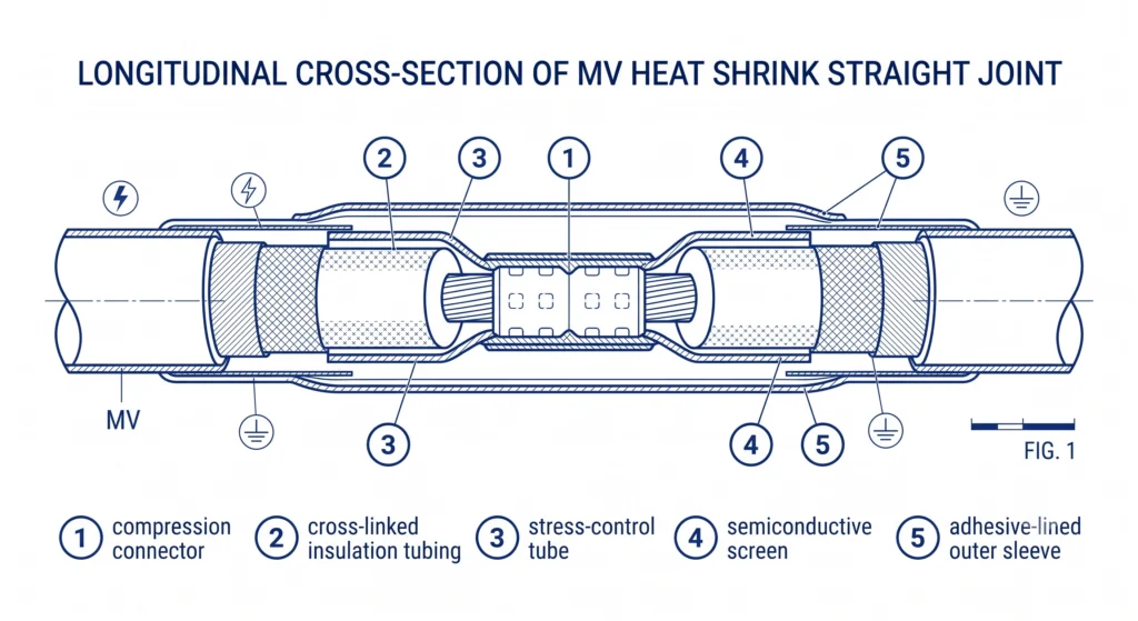
A cable joint is a rebuilt cable section, not a single component. When two ends meet inside a splice, the joint reconstructs every layer the manufacturer built into the run: conductor path, primary insulation, stress-control interface, semiconductive screen, and outer moisture seal. Heat shrink technology does this with cross-linked polymeric sleeves that recover onto the cable when heated, typically in the 120–150 °C range from a controlled propane torch.
Conductor Connection and Current Path
The joint begins at the connector, where conductors are mechanically or compression-joined. This connection carries the full continuous current, commonly 200 A up to 800 A depending on conductor size, without a hot spot. A poorly crimped barrel raises contact resistance, and the resulting localized heating is a common precursor to field failure.
Insulation and Stress Control
The joint restores dielectric strength across the cut-back region, where cross-linked insulation tubing recovers over the connector. At the semiconductive screen edge the field concentrates sharply, so a stress-control layer, a geometric stress cone or a high-permittivity stress-grading tube, redistributes it.
The stress-control material typically carries a relative permittivity around εr ≈ 20–30, far above the εr ≈ 2.3 of XLPE insulation, which pulls the equipotential lines apart and lowers the tangential stress at the screen edge.
Environmental Sealing
The final layers restore the outer jacket. Adhesive-lined sleeves melt and flow during recovery, bonding to the jacket to block water ingress, decisive for buried and duct joints where standing water is routine. These four layers ground every selection decision that follows, across ZeeyiElec heat shrink cable termination and joint families for distribution voltage classes.
Layered cross-section of a heat shrink straight joint, showing how the connector, cross-linked insulation, stress-control layer, screen, and adhesive-lined outer sleeve rebuild the cable.
What Separates a Project-Grade Joint Kit from a Generic One
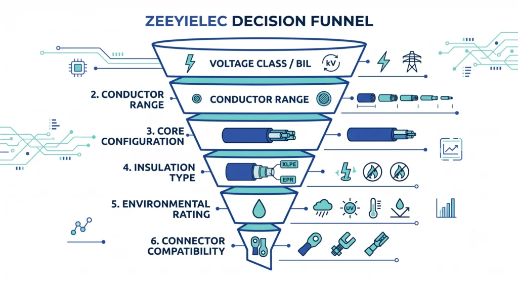
Whether a kit survives 30 years underground or fails at acceptance testing rarely comes down to sleeve material, but to whether the specification envelope matches the cable and installation. Six parameters decide that match; lock all of them before shortlisting.
Voltage Class and BIL Matching
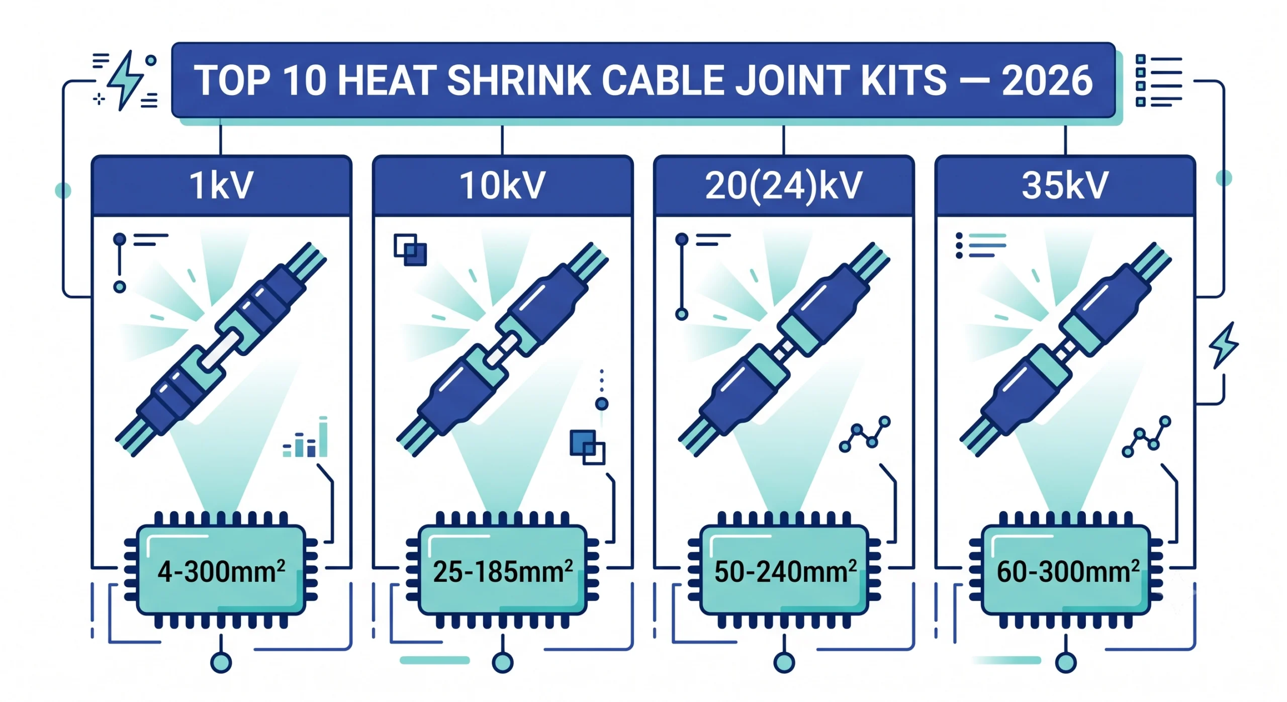
The kit rated voltage must align with the cable rated voltage, not the nominal system voltage. Kits are built to discrete classes, 1kV, 10kV, 20(24)kV, and 35kV, each with a corresponding basic insulation level. A 12kV kit on a 24kV cable under-designs the stress-control interface regardless of workmanship.
Conductor Cross-Section Range
Each kit covers a conductor window, spanning 25 mm² to 800 mm² across a family but a narrower band per kit. The connector barrel and sleeve recovery ratio set the limit: a sleeve recovering more than roughly 3:1 will not seal reliably.
Single-Core vs Three-Core Configuration
Core count changes sleeve geometry. Three-core joints need breakout components and individual core insulation that single-core kits lack, so this is not interchangeable.
Insulation Type Compatibility
Adhesives and stress-control chemistry must suit the cable insulation. XLPE and EPR cables accept standard heat shrink chemistry, while paper-insulated lead-covered (PILC) cable needs transition components to migrate from an oil-impregnated to a dry polymeric system.
Environmental Rating
Indoor, outdoor, direct-buried, and duct-bank installations impose different sealing and UV demands. Outdoor kits add tracking-resistant layers; buried kits prioritize adhesive water-blocking at the jacket interface.
[Expert Insight]
Check rated voltage against the cable rating, never the nominal system voltage — the most common under-specification.
Keep conductor size mid-range in the kit window, not at the marginal recovery edge.
Treat single/three-core and XLPE/PILC as hard gates; no premium kit bridges these alone.
Write the installation environment into the RFQ; it drives the outer-seal requirement.
The same discipline runs across the broader cable accessories product range. Getting these right upfront prevents specification gaps that otherwise surface during on-site testing.
The six-parameter funnel a distribution engineer applies before shortlisting a joint kit, from voltage class down to connector compatibility.
Top 10 Heat Shrink Cable Joint Kits for Distribution Projects
There is no universal best kit, only the one matching your cable and route. The ten types below cover the voltage classes, conductor windows, and core configurations common in distribution work. Use it as a selection matrix: find the row whose class and construction match your cable, then narrow by environment.
Comparison Table: 10 Heat Shrink Joint Kit Types by Application
#
Kit Type
Voltage Class
Conductor Range
Core Config
Best-Fit Application
1
LV straight joint
1kV
25–300 mm²
Single-core
Service cables, LV feeders
2
LV multi-core joint
1kV
25–240 mm²
3/4-core
LV distribution, buried mains
3
MV single-core straight
10kV
35–630 mm²
Single-core
Ring main, radial feeders
4
MV three-core straight
10kV
35–300 mm²
Three-core
Older three-core XLPE networks
5
MV transition joint
10kV
50–400 mm²
Single/three
PILC-to-XLPE retrofits
6
MV single-core straight
20(24)kV
50–800 mm²
Single-core
Urban distribution, duct banks
7
MV three-core straight
20(24)kV
50–300 mm²
Three-core
Compact three-core systems
8
MV transition joint
20(24)kV
70–400 mm²
Single/three
Mixed-insulation upgrades
9
HV single-core straight
35kV
70–800 mm²
Single-core
Long feeders, sub-transmission
10
HV outdoor joint
35kV
95–800 mm²
Single-core
Exposed, aerial-to-buried spans
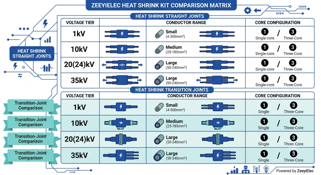
Conductor windows widen at higher voltage classes, up to 800 mm² at 35kV, while three-core kits narrow toward 300 mm² because breakout geometry limits core size. Transition joints exist because a straight polymeric kit cannot safely bridge oil-impregnated paper cable to dry XLPE. If your project mixes technologies, the cold shrink versus heat shrink selection framework helps decide whether a heat-recovered kit is right before you lock a row.
A comparison matrix mapping the four voltage tiers against conductor range and core configuration, with transition-joint rows highlighted.
Field Selection Realities: Matching the Kit to the Trench
A datasheet describes ideal conditions; the trench does not. Two field realities override catalogue selection once the joint is buried.
Duct Bank and Manhole Moisture Exposure
Manholes flood. On one 20(24)kV urban feeder project, straight joints in a duct-bank manhole sat in standing water for weeks between wet-season rains. The kits were correctly rated at 24kV for a 240 mm² conductor, but the outer sealing had been treated as a formality rather than a primary defense. The lesson: in any manhole or duct bank, the adhesive-lined outer sleeve is the survival layer. Water against a marginally sealed jacket migrates along the cable to the stress-control region, where sustained moisture drives partial discharge and eventual breakdown.
PILC-to-XLPE Transition Jointing on Retrofits
Replacing aged 10kV paper-insulated lead-covered (PILC) cable with modern XLPE cannot use a standard straight joint; the two insulation systems differ chemically and electrically. The correct choice is a transition joint that seals the lead sheath and oil barrier on the PILC end while restoring polymeric insulation on the XLPE end. Forcing a standard joint is expensive, because failure surfaces months later at the paper-to-polymer boundary. Both cases share a root cause: the kit was chosen against the cable spec alone, not the installed environment. The guard is a structured installation quality control checklist for MV accessories that forces environment and sealing checks into the pre-energization workflow.
Installation and Commissioning Factors That Decide Kit Longevity
Two identical kits, installed by two crews on the same feeder, can differ in service life by decades. The kit sets the ceiling; workmanship decides how close you get. A well-selected joint targets the cable 25–40 year design life, only if recovery, preparation, and ambient control stay in tolerance.
Torch Control and Recovery Quality
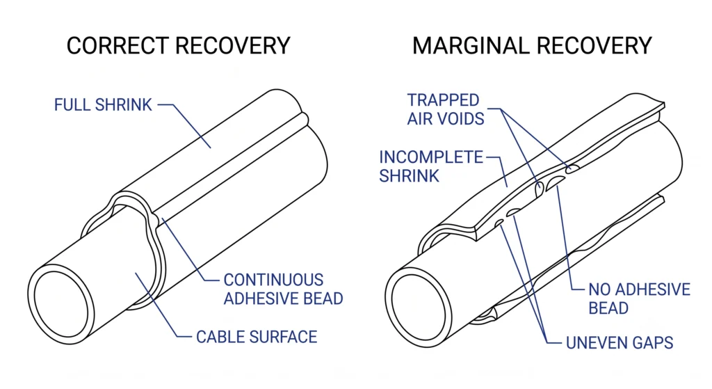
Recovery is controlled, not “apply flame until it shrinks.” The sleeve recovers correctly in the 120–150 °C range, the flame moving steadily so the shrink runs center-outward and drives trapped air ahead of it. Overheating scorches the polymer and degrades dielectric properties; underheating leaves the adhesive unflowed. A continuous adhesive bead at the sleeve edges confirms the seal; a broken bead means voids remain.
Cable Preparation Tolerances
Cut-back dimensions, insulation strip length, semicon removal, and screen termination point, are specified in millimetres for a reason. A ragged or over-cut screen creates local field enhancement the stress-control layer must compensate for. Clean, accurate preparation lets that layer do its job; sloppy prep overloads it.
Ambient Temperature and Contamination
Jointing in a cold trench slows adhesive flow and can leave a marginal seal even when recovery looks complete. Dust, moisture, and grease prevent adhesion. Crews who clean and pre-warm produce joints that survive; those who skip prep produce joints that pass the first test and fail two winters later.
[Expert Insight]
Look for a continuous adhesive bead at every sleeve edge — the fastest proof the seal bonded.
Hold recovery in the 120–150 °C band; scorching and under-recovery both destroy the joint.
Re-check cut-back dimensions against the instruction sheet before recovery, not after.
Pre-warm and clean surfaces in cold trenches; workmanship outweighs kit price.
Correct versus marginal heat shrink recovery at the sleeve edge; a continuous adhesive bead confirms sealing, while trapped voids signal an incomplete recovery.
Standards and Quality Anchors for Joint Kit Procurement
A kit’s real quality shows in the type-test report, not the catalogue photo. The documentation a supplier can produce is the best predictor of field performance, and it is leverage to use before the purchase order.
Type-Test Certificates to Request
The core qualification for MV cable accessories is the accessory type test, subjecting a representative joint to a defined electrical and thermal stress sequence. The framework is the IEC 60502 series for extruded cable accessories from 1kV to 30kV, with [VERIFY STANDARD: IEC 60502-4 covering test requirements for cable accessories at 6kV to 30kV]. A supplier who can produce that report shows the design passed independent qualification.
Partial Discharge and Voltage Withstand
Partial discharge testing detects internal voids and interface defects before they propagate. A qualified MV joint is expected to show partial discharge below a defined threshold, commonly a few picocoulombs, at a test voltage above rated. The AC voltage withstand test confirms it holds rated dielectric strength.
Heating Cycle and Thermal Endurance
Because joints expand and contract with load, the heating-cycle test loads the joint to conductor temperatures around 90–95 °C for XLPE, then cools it, exposing weaknesses that appear only under thermal movement. Cross-check test-method detail against the International Electrotechnical Commission official standards catalogue rather than supplier summaries. The principle: request the evidence, confirm the class and conductor range match your order, and treat a missing type-test report as a red flag.
Request a Project-Matched Heat Shrink Joint Kit Quote
Selecting a kit is a disciplined match: voltage class against cable rating, conductor window against cross-section, core configuration against construction, sealing against the trench. Get those four right, confirm the type-test evidence, and installation discipline does the rest. To avoid a specification gap, let the supplier engineering side check the match first. Share four data points per joint location:
Cable rated voltage and class (10kV, 20(24)kV, 35kV)
Conductor cross-section in mm² and material (Cu or Al)
Construction — single-core or three-core, and insulation type (XLPE, EPR, or PILC)
Environment — direct-buried, duct bank, indoor, or outdoor
With those, ZeeyiElec can confirm the correct kit from the heat shrink joint families, flag any transition-joint need, and return technical feedback with the quotation. For projects spanning terminations and joints, the full transformer and cable accessory product range can be quoted together. Send your cable schedule and single-line drawings to receive a matched recommendation with voltage class, conductor range, and documentation set before anything ships.
Frequently Asked Questions
What is the difference between a heat shrink cable joint and a termination?
A joint splices two cable ends into a continuous run, while a termination finishes a single end for connection to equipment; both restore insulation and stress control, but joints add a conductor connector and symmetrical sealing on both sides.
Do I need a different kit for aluminium versus copper conductors?
The sleeve and stress-control components are usually common, but the connector must match the conductor metal and size, so aluminium runs often need bimetallic connectors to avoid galvanic issues at the crimp.
How long does it take to install a heat shrink joint in the field?
A single MV straight joint commonly takes a trained two-person crew a few hours including preparation, though duct-bank access, three-core breakouts, and cold weather extend it considerably.
Can heat shrink joints be installed on live or energized cables?
No, jointing requires the section de-energized, isolated, and earthed, since the process involves cutting into the insulation and applying an open flame near the conductor.
What is the maximum conductor size for distribution heat shrink joints?
Distribution kits commonly reach up to 800 mm² at the higher MV classes, but the practical ceiling depends on the specific connector and recovery range, so always confirm against the datasheet.
How do I know if a supplier’s joint kit is genuinely qualified?
Request the type-test certificate and confirm the tested voltage class and conductor range cover your application; a supplier unable to produce independent test documentation is a signal to reconsider.
yoyo shi
Yoyo Shi writes for ZeeyiElec, focusing on medium-voltage accessories, transformer components, and cable accessory solutions. Her articles cover product applications, technical basics, and sourcing insights for global electrical industry buyers.




 English
 한국어
한국어 العربية
 Español
 हिन्दी
 தமிழ்
தமிழ் Deutsch (Sie)
 Français
 Português do Brasil
 Русский