A cable termination ends a cable at an equipment connection point switchgear, transformer terminal, or motor and manages the transition from cable insulation to an exposed electrical interface. A cable joint connects two cable lengths mid-run, restoring full insulation continuity without atmospheric exposure. The function boundary is absolute: if the cable ends, specify a termination; if it continues, specify a joint. Technology choice cold shrink or heat shrink applies to both, but only after this boundary is confirmed.
What Each Component Actually Does: Function Boundaries Defined
The confusion between terminations and joints is understandable on paper but dangerous in the field. Both involve cutting back the cable, both use shrink technology, and both appear in the same accessory catalogue. The distinction matters because the governing physics and failure modes are entirely different.
What Is a Cable Termination?
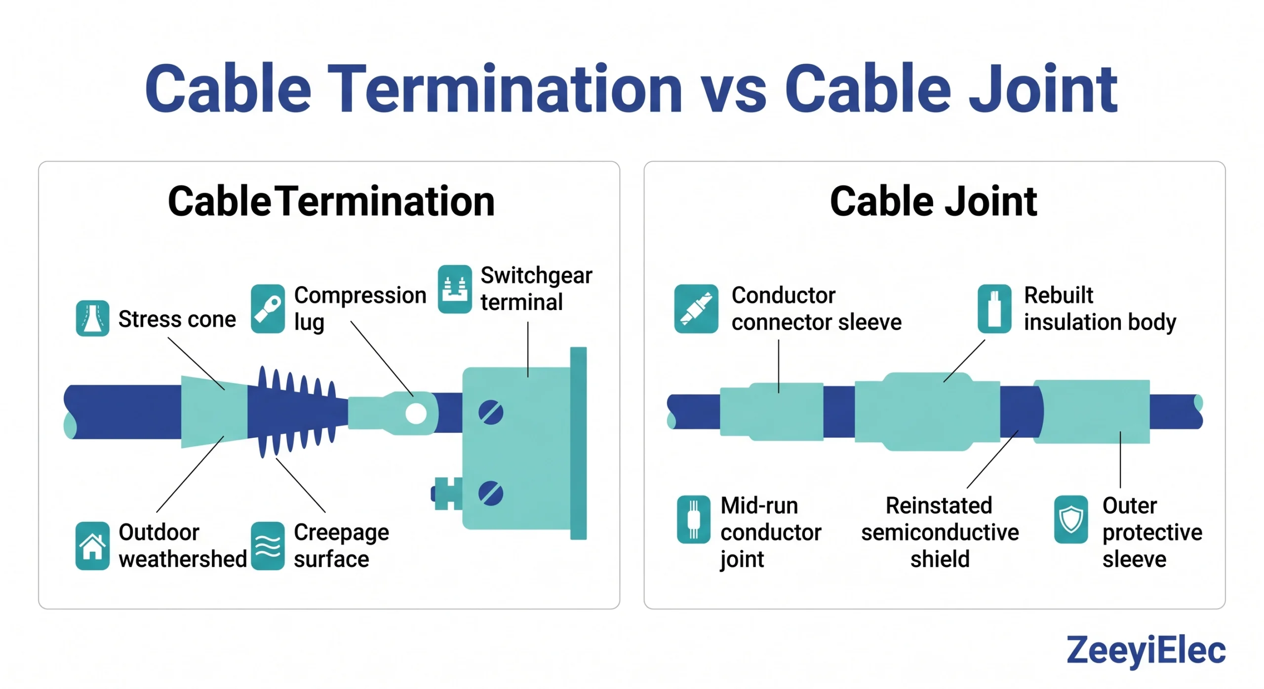
A termination manages the transition from cable insulation to an open electrical interface. The semiconductive screen is removed over a precise length, and a stress cone redistributes the dielectric field concentration at the cut-back edge. Without it, stress at the screen edge can reach 6–8 kV/mm locally at 15 kV class enough to initiate partial discharge within months. The stress cone brings this down to a manageable 2–4 kV/mm across the grading length. Above the insulation interface, creepage distance between the live conductor and earthed screen must match the pollution severity class of the site. The termination ends at a compression lug connecting the conductor to the equipment terminal.
What Is a Cable Joint?
A joint restores full insulation continuity across a mid-run conductor connection no atmospheric exposure, no creepage requirement. The conductor connector sleeve is crimped first; then the insulation body is rebuilt over it, semiconductive shielding is reinstated, and an outer mechanical protection layer is applied. The joint must replicate the original cable’s dielectric performance. An air gap between the sleeve and insulation body even 0.5 mm is a partial discharge initiation site that will erode insulation progressively under service voltage.
The Boundary in One Sentence
If the cable ends at equipment: termination. If the cable continues: joint. Resolving this before opening a catalogue eliminates the majority of accessory mismatches.
Fig. 1: Cross-sectional comparison of a medium-voltage cable termination (left) and cable joint (right), identifying the stress cone, semiconductive screen cut-back, compression lug, conductor connector sleeve, rebuilt insulation body, and outer mechanical protection layer.
Electrical and Mechanical Specification Comparison
Once component type is confirmed, specification matching requires six parameters from the cable data sheet. A single incorrect value voltage class, conductor CSA, or insulation OD produces an accessory that passes incoming inspection and fails within its first thermal cycling season.
Parameter
Cable Termination
Cable Joint
Voltage class (Um)
Governs creepage length and stress cone geometry
Governs insulation body dielectric withstand
Creepage distance
Required: 25–31 mm/kV at Class III pollution (outdoor)
Not applicable — enclosed installation
Conductor CSA range
Must fall within kit range (mm²)
Must fall within kit range (mm²)
Current rating variable
Lug-to-terminal contact resistance
Connector sleeve crimp resistance
Insulation interface
XLPE/EPR: silicone or polyolefin; PILC: verify
XLPE/EPR: silicone or polyolefin; PILC: verify
After-laying test
PD measurement + HV withstand before energisation
PD measurement + HV withstand before energisation
Voltage class drives the largest specification errors. A 12/20 kV cable has Um = 24 kV accessories must be rated for Um ≥ 24 kV. Applying a 12 kV-class accessory to a 24 kV system undersizes the stress cone, insulation body thickness, and for terminations creepage length simultaneously. PILC cables (paper-insulated lead-covered) require explicit manufacturer confirmation of interface material compatibility regardless of technology selected; standard XLPE-optimised accessories are not interchangeable.
Type testing for MV cable accessories covering both terminations and joints in the 1 kV–30 kV range falls under IEC 60502-4, which defines partial discharge, impulse withstand, voltage withstand, and thermal cycling test sequences. A routine test certificate is not a substitute for a type test certificate at the procurement stage.
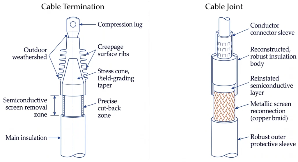
[FIG-02] — Style B (flat infographic, blue #2b4197 primary, teal #78d3ca secondary): Visual comparison card — 6 parameter rows, termination vs. joint columns, icon-tagged rows, colour-coded cells.
Fig. 2: Specification comparison card for medium-voltage cable terminations and joints across six parameters, including voltage class Um, creepage distance requirements, conductor CSA range, current rating variables, insulation interface compatibility, and after-laying test requirements.
[Expert Insight] Specification Traps That Reach Site
Cable OD tolerance variation means a 185 mm² cable from one manufacturer may measure 1–2 mm outside another manufacturer’s kit acceptance range always verify against the actual drum label, not the spec sheet nominal.
A routine test certificate confirms production batch consistency; it does not confirm that the design has passed impulse and thermal cycling type tests. Treat these as different documents.
For outdoor terminations above 1000 m altitude, creepage and clearance values require derating at 2000 m, effective air clearance is approximately 80% of the sea-level rated value.
Installation Environment and Application Mapping
Electrical specification confirms an accessory can handle the voltage. Environment mapping determines whether it survives the physical conditions across a 25–30 year service life.
Outdoor and Indoor Terminations
Outdoor terminations face UV radiation, pollution accumulation, and wetting cycles. The weathershed profile provides the creepage length for the pollution severity class. Silicone rubber weathersheds transfer hydrophobic properties to contamination deposits, temporarily suppressing leakage current even when wet a self-recovery mechanism polyolefin surfaces do not replicate. Above 1000 m altitude, reduced air density lowers flashover voltage; specify an upgraded pollution class or confirm derating with the manufacturer. Indoor terminations inside switchgear or ring main units (RMUs) shift the specification focus entirely to interface geometry: lug style, phase centre spacing, and equipment bolt pattern.
Underground Joints
Direct-buried joints face compaction forces, groundwater, and thermal cycling from load variation. Heat shrink outer protection requires full adhesive activation in cold ambient conditions or confined excavations, incomplete activation leaves capillary moisture paths. Cold shrink outer protection applies sustained radial pressure without heat, making it the more reliable choice in cold, wet, or confined installation conditions. In duct banks and cable tunnels, mechanical risk reduces but thermal derating in high cable-density configurations becomes the dominant design variable.
Field Case: Function Boundary Misapplication
A 15 kV underground feeder project required mid-run joins across six manholes. At one location with a 900 mm working envelope, the crew substituted a cold shrink termination from site stock rather than sourcing a compact joint kit. Within eight months, PD monitoring identified a sustained discharge source at that manhole the exposed screen cut-back in the enclosed, humid environment was generating discharge the termination was never designed to manage. Rectification required 14 hours of outage and cost approximately 3× the original joint kit price. The correct resolution at planning stage: identify compact joint kits with reduced installation envelopes, which are a standard product line offering from MV cable accessory manufacturers.
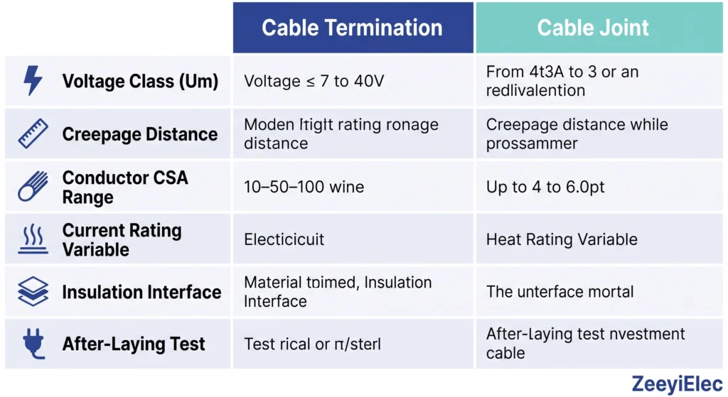
Fig. 3: Application decision matrix mapping six medium-voltage installation scenarios — switchgear entry, transformer terminal, overhead transition, direct burial, duct bank, and confined-space manhole — to component type and technology recommendations for cold shrink and heat shrink cable accessories.
Cold Shrink vs Heat Shrink Technology Across Both Component Types
Cold shrink and heat shrink are not quality tiers they are distinct engineering approaches. Both are available for MV terminations and joints from 6.6 kV through 33 kV. The selection decision belongs at Step 3 of the procurement sequence, not at the price comparison stage.
Cold Shrink
Pre-expanded silicone rubber contracts under its own elastic memory when the inner core is removed no heat source required. Silicone retains elasticity from –50 °C to +180 °C, maintaining radial interface pressure through load cycling, ambient temperature swings, and multi-decade service. For terminations, inherent hydrophobicity suppresses leakage current formation under contaminated wet conditions. For joints, torch-free installation is operationally decisive in confined spaces, explosive atmospheres, cold climates, and sites above 1000 m where propane handling introduces additional hazard. Conductor range per kit is narrower than heat shrink projects with mixed CSA cables may require multiple kit variants.
Heat Shrink
Cross-linked polyolefin tubing recovers under torch or hot-air activation at 110–135 °C. The adhesive liner softens and flows into surface irregularities, providing the moisture seal as the assembly cools. A single kit covers a wider conductor OD range, simplifying inventory on mixed-conductor projects. For joints, each layer must fully recover and cool before the next is applied a rushed sequence produces inter-layer delamination that manifests as partial discharge within the first operating year. Heat shrink carries a longer utility network track record and broader manufacturer support for unusual cable constructions.
[Expert Insight] Technology Selection in Practice
Cold shrink’s narrower OD range per kit is a procurement planning issue, not a performance limitation identify conductor range requirements before ordering to avoid mid-project substitutions.
Below 5 °C ambient, heat shrink adhesive activation requires extended heating time and careful technique management; cold shrink installation speed is unaffected by low temperature.
For PILC cable interfaces, request material compatibility confirmation from the manufacturer for both technologies do not assume compatibility based on voltage class alone.
Common Failure Modes: What Goes Wrong and Why
Termination Failures
Partial discharge at the screen cut-back edge is the most frequent termination failure mode triggered by surface contamination, incorrect cut-back length, or cable OD outside the accessory’s specified range. Tracking on the creepage surface follows wet contamination cycling on polyolefin weathersheds without hydrophobic recovery. Moisture ingress at the cable entry seal develops through incomplete adhesive activation or insufficient radial pressure at the lower OD limit of the kit range water accumulates inward through thermal pumping across load cycles. Mechanical pull-out at the compression lug occurs when cable cleating is beyond the manufacturer’s recommended distance from the termination body, allowing conductor movement that initiates fretting corrosion at the lug interface.
Joint Failures
Insulation voids at the connector sleeve are almost always installation-quality driven a wrong crimp die index leaves the sleeve OD outside the insulation body’s designed contact tolerance, creating a partial discharge initiation site that erodes insulation progressively. Shielding discontinuity from incomplete semiconductive layer restoration produces uncontrolled field boundaries that accelerate degradation wherever moisture is present. Outer sheath damage during backfill compaction when the sleeve has not fully cured before soil is returned creates mechanical stress concentrations that propagate into the insulation body over subsequent thermal cycles.
Field Case: Crimp Die Index Error
A 33 kV heat shrink joint on a 185 mm² XLPE cable in a duct bank failed at month 22 during summer peak load. Post-mortem found two of four crimp positions at incorrect die closure, leaving the sleeve OD 1.8 mm oversize on one face sufficient to prevent insulation body contact. Thermal imaging at month 6 had recorded a 4 °C temperature differential at the joint location; the network’s intervention threshold was 8 °C. By month 21, the differential reached 14 °C; failure followed nine days later. A 90-second post-crimp sleeve OD measurement at installation would have caught the defect before backfill. Trust qualifier: failure timelines are sensitive to load profile, duct fill density, and the magnitude of the initial defect the 1.8 mm excess in this case was a significant departure from specification.
Selection Framework: Four Steps to a Correct Specification
Step 1 — Endpoint or Mid-Point?
Walk the cable route drawing. If the cable ends at equipment: termination. If it continues: joint. Resolve this from as-built drawings, not verbal site descriptions route drawings are frequently revised during construction, and component type at tender may not match as-built geometry by installation date.
Step 2 — Collect Cable Electrical Parameters
Rated voltage designation → derives Um. Insulation type: XLPE (cross-linked polyethylene), EPR (ethylene propylene rubber), or PILC. Conductor material and CSA (mm²). Outer sheath OD (mm). Number of cores: single or three. Do not estimate any value — one incorrect parameter produces a mismatched accessory.
Step 3 — Map the Installation Environment
For terminations: indoor or outdoor, pollution severity class (I–IV), altitude above 1000 m. For joints: direct-buried, ducted, or tunnel; confined space or explosive atmosphere classification; ambient temperature at installation.
Step 4 — Confirm Technology
Confined space, altitude >1000 m, cold climate (<5 °C ambient), heavy outdoor pollution → cold shrink. Mixed conductor range across project, open-trench warm-climate installation, experienced crew → heat shrink acceptable. When both technologies are acceptable, favour consistency with the network’s existing installed base over optimisation applied inconsistently across crews with different training backgrounds.
ZeeyiElec supplies cold shrink and heat shrink cable accessories for MV terminations and joints from 6.6 kV–33 kV. Share your cable data sheet and installation environment our engineering team returns a matched accessory recommendation and quotation. OEM and project-volume orders supported with export documentation. 📩 [email protected] · +86 150 5877 8024
Correct accessory selection is a necessary condition for reliable cable system performance not a sufficient one. A correctly specified cold shrink joint installed with a wrong crimp die produces the same void-at-sleeve failure documented in the field case above. Specification and installation quality are sequential dependencies: neither compensates for failure in the other.
Pre-Order Verification
Confirm the manufacturer can supply a type test certificate for the specific model and voltage class not a routine test certificate. Verify conductor CSA and outer sheath OD against the actual cable drum label, not the nominal spec sheet. At goods receipt, open and verify kit contents against the manufacturer’s component checklist before signing a missing mastic tape or incorrect lug size discovered mid-installation, with the cable already prepared and the excavation open, converts a minor receiving error into a project delay.
Installation Stage Gates
Semiconductive screen removal must reach the specified cut-back length within ±5 mm and leave no carbon residue on the insulation surface carbon at the stress cone interface is a partial discharge initiation site that cannot be corrected after the accessory is applied. For joints, measure connector sleeve OD at each crimp position against the manufacturer’s post-crimp OD range before applying the insulation body. This check takes 90 seconds and eliminates the most common joint failure mode.
After-Laying Tests
Conduct partial discharge measurement and reduced-level high-voltage withstand on the completed circuit before energisation. Installation-induced voids detected at this stage are repairable; the same defects discovered post-energisation require outage, excavation, and full accessory replacement at 3–10× the original correction cost.
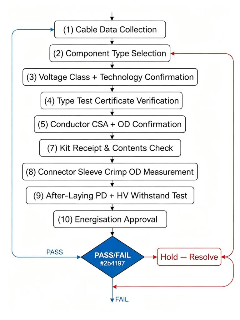
Fig. 4: Linear quality checkpoint flowchart for medium-voltage cable accessory procurement and installation, proceeding from cable data collection through type certificate verification, kit receipt inspection, surface preparation, connector sleeve crimp measurement, and after-laying electrical testing to energisation approval.
What is the fundamental difference between a cable termination and a cable joint?
A termination ends a cable at an equipment connection point and manages the electrical transition from cable insulation to an exposed interface, requiring a stress cone for field grading and creepage length matched to the site pollution class; a joint connects two cable sections mid-run and restores full insulation continuity without atmospheric exposure, with no creepage requirement but strict demands on insulation body contact quality and shielding continuity.
Can a cable termination be used at a mid-run splice location?
No a termination’s stress cone and creepage surface are engineered for conditions at a cable endpoint; placing one in an enclosed mid-run location exposes the screen cut-back edge to humidity and contamination it cannot manage, and omits the insulation restoration and shielding continuity functions that a joint provides.
What voltage range do MV cable terminations and joints typically cover?
Both components for medium-voltage distribution networks typically cover 6.6 kV through 33 kV, selected by the cable’s Um (maximum system voltage) rather than nominal operating voltage, with discrete class steps at Um = 12 kV, 17.5 kV, 24 kV, and 36 kV.
When is cold shrink the better choice over heat shrink for MV cable accessories?
Cold shrink is preferred in confined spaces, explosive atmospheres, altitudes above approximately 1000 m, cold ambient conditions below 5 °C, and outdoor termination environments with heavy pollution or coastal exposure in each case, torch-free installation logistics or silicone hydrophobicity provides a performance advantage heat shrink cannot replicate.
What causes partial discharge in MV cable accessories?
In terminations, PD most commonly originates at the screen cut-back edge when the stress cone fails to achieve intimate contact with the cable insulation due to surface contamination, incorrect cut-back length, or cable OD outside the kit’s specified range; in joints, PD originates at voids between the connector sleeve and insulation body caused by incorrect crimp die selection leaving the sleeve OD outside the designed contact tolerance.
How long should a correctly installed MV cable accessory last?
Design life for correctly specified and installed MV cable accessories typically ranges from 25 to 40 years, consistent with the cable system design life; accessories with installation defects such as incomplete adhesive activation, incorrect crimps, or contaminated insulation surfaces can fail within 1–5 years, while well-installed accessories in moderate environments routinely reach 30 or more years without intervention.
What after-laying tests are required before energising a new MV cable circuit?
Completed MV cable circuits typically require partial discharge measurement to detect installation-induced voids and a high-voltage withstand test at a reduced level commonly around 80% of type test voltage for a defined duration applied across the full circuit including all terminations and joints; specific test levels are defined by the network operator specification and applicable IEC standards for the cable and accessory voltage class.
yoyo shi
Yoyo Shi writes for ZeeyiElec, focusing on medium-voltage accessories, transformer components, and cable accessory solutions. Her articles cover product applications, technical basics, and sourcing insights for global electrical industry buyers.