Solid state transformers (SSTs) replace the passive distribution transformer with an actively controlled power-electronics system. This guide covers how they work, where they fit, and why conventional transformers usually remain the practical choice.
What Is a Solid State Transformer? Core Definition and System Architecture
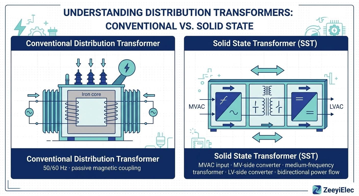
A solid state transformer (SST) is a power-electronics conversion device replacing the passive line-frequency magnetic coupling of a conventional distribution transformer with an actively switched converter chain around a medium-frequency transformer (MFT). It steps MV supply down to LV with galvanic isolation, adding bidirectional power flow, fast voltage regulation, DC output ports, and power-quality functions. Commercial MV deployment remains limited; most figures come from prototypes and pilots. The engineering reference literature on solid-state transformers summarizes the IEEE research stream.
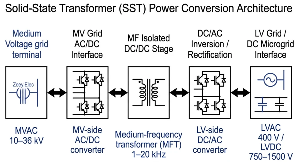
Figure 1. Block diagram of the three-stage solid-state transformer architecture, showing the MV-side converter, the medium-frequency transformer, and the LV-side converter that together provide galvanic isolation and bidirectional power flow.
The Three-Stage Conversion Chain: MVAC → MFT → LVDC
Stage 1 rectifies the MVAC supply — typically 10–36 kV — into a DC link; Stage 2 transfers energy across the galvanic boundary via the MFT at 1–20 kHz; Stage 3 synthesizes LVAC output (commonly 400 V three-phase) or LVDC (often 750–1500 V DC for EV charging and DC microgrids).
How an SST Differs from a Conventional Distribution Transformer
A conventional distribution transformer is a passive, unidirectional, 50/60 Hz magnetic device tested against the IEC 60076 series, supported by a mature accessory ecosystem — bushings, tap changers, fuse assemblies. An SST replaces that passive coupling with active switching, enabling dynamic voltage regulation, bidirectional flow, and harmonic filtering. For projects that continue on conventional transformers, the established transformer accessories ecosystem remains the practical specification path.
The Physics: Why Higher Frequency Shrinks the Transformer and Enables Bidirectional Power Flow
A conventional transformer is locked to 50/60 Hz; an SST’s converters generate their own internal frequency — typically 1–20 kHz — cascading through core size, isolation design, and controllability.
Why Operating at Kilohertz Frequencies Reduces Core and Winding Volume
For a transformer operating at frequency f, the induced voltage per turn scales as V ∝ B × A × f, where B is the core flux density and A the core cross-section. Raising f from 50/60 Hz to the 1–20 kHz range therefore allows a much smaller magnetic core to support the same voltage transformation — the core reason an SST can be substantially lighter and more compact than a line-frequency unit of equal rating.
Prototype literature for MV SSTs reports 30–50% weight reductions versus line-frequency units, depending on cooling and packaging. The smaller core does not automatically mean a smaller enclosure — power electronics and thermal management occupy much of it.
Galvanic Isolation and the Role of the Medium-Frequency Transformer
The MFT is the only component crossing the galvanic boundary between MV and LV, so it carries the full insulation duty at kilohertz rates. High dv/dt changes insulation behavior versus 50/60 Hz — creepage, partial-discharge inception, and inter-layer voltage distribution need dedicated attention. This insulation burden, not the magnetic core, sets the ceiling on internal frequency.
Switching Devices in SST Design: SiC MOSFETs and IGBTs
SiC MOSFETs (1.2/3.3/10 kV; junction 150–175°C) suit fast switching with low losses; IGBTs (to 6.5 kV; 125–150°C) carry higher current at medium frequency. Choice depends on power level, frequency, and thermal budget.
Because both converters are actively switched, current can reverse direction on command — enabling regenerative operation and backfeed no passive transformer can perform. The electromagnetic induction fundamentals in our transformer fundamentals guide provide the base physics.
SST vs Conventional Transformer: Engineering Comparison
This is not a “better versus worse” question but one of operating envelope — the conventional unit is a proven commodity; the SST’s advantages appear only where usable.
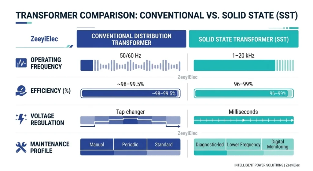
Figure 2. Side-by-side comparison of conventional distribution transformer and solid-state transformer characteristics, including operating frequency, efficiency bands, voltage-regulation response, and maintenance profile at distribution-class ratings.
SST vs Conventional Transformer: Key Parameters at a Glance
Parameter
Conventional distribution transformer
SST (current state)
Operating frequency
50/60 Hz (grid-locked)
1–20 kHz internal (converter-generated)
Typical voltage class
LV to 36 kV (IEC 60076 ecosystem)
10–36 kV in demonstrations
Efficiency at rated load
~98–99.5%
96–99% in pilots, test-condition dependent
Voltage regulation
Passive; tap-changer dependent
Dynamic, sub-cycle-class response
Bidirectional power flow
Not possible
Yes, inherent
Harmonics and power quality
None (passes system harmonics)
Active filtering capability
Maintenance profile
Mature utility practice
Power-electronics spares, specialist skills
Efficiency, Size, and Weight at Distribution-Class Ratings
At rated load, conventional units reach roughly 98–99.5% efficiency; SST prototypes report 96–99%. The comparison is load-point dependent — converter losses are relatively constant and dominate at light load.
Expert Insight — comparing efficiency claims in procurement
Demand the load point and cooling configuration behind every efficiency figure.
Add auxiliary and cooling power at zero output — it can exceed conventional no-load losses.
Ask whether weight claims include enclosures and cooling.
Voltage Regulation, Power Quality, and Harmonics Capability
Conventional transformers regulate voltage only through tap changing — off-circuit taps need de-energized operation; on-load tap changers respond over seconds to minutes. An SST regulates at converter speed, within milliseconds, and can filter harmonics and provide reactive support.
Cost, Commercial Maturity, and Lifecycle Reality
SST-based systems are generally reported to cost several times more than a conventional transformer of similar rating, driven by power electronics and cooling. Lifecycle planning differs: conventional units fail predictably in oil, gaskets, and bushings with a mature replacement market; SSTs bring electronics obsolescence and semiconductor spares.
Real-World Applications and Field Deployment Status
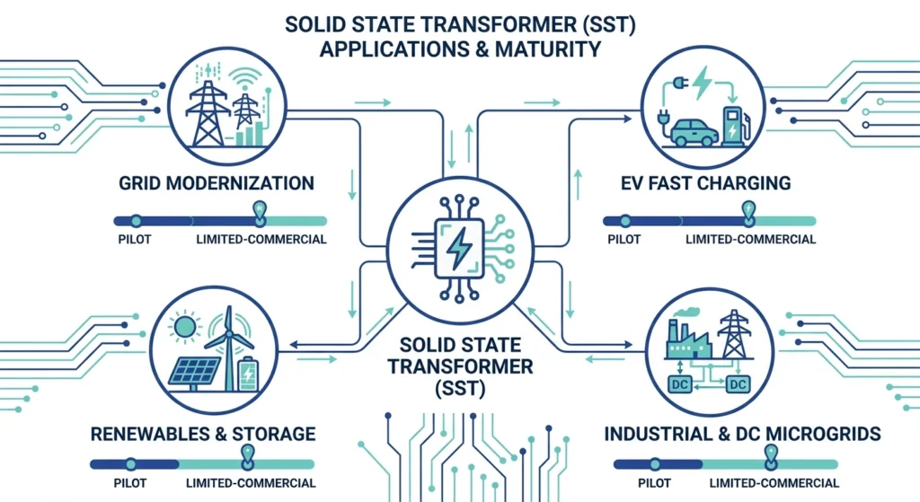
As of 2026, MV SSTs sit at pilot and limited-commercial stage — demonstration-scale and project-specific, not fleet-wide replacements.
Figure 3. Application map for solid-state transformer deployment, plotting grid-modernization, EV fast-charging, renewable-integration, and industrial use cases with commercial-maturity markers as of 2026.
Smart Grid and Grid-Modernization Roles
The clearest fit is feeders where voltage and power-flow control justify the cost: long feeders with voltage-drop problems, high distributed-generation penetration, or circuits needing fast islanding. An SST can hold output within utility voltage bands commonly set at ±5% (for example ANSI C84.1 Range A) and operate in grid-forming mode — a controllable voltage source, not a passive element.
EV Fast Charging, Renewable Integration, and Industrial Use Cases
EV fast charging benefits from direct DC output (750–1500 V DC), eliminating AC/DC stages for 150–350 kW stalls with storage; renewables use bidirectional flow for PV, battery, and V2G; data centers value the filtering and voltage control.
The MV feeders these applications connect through rely on the same proven cable ecosystem — terminations and joints from cold shrink and heat shrink cable accessories — that serves conventional networks.
Pilot Projects and Field-Trial Status as of 2026
Demonstrations span university platforms, manufacturer prototypes, and utility pilot feeders, most advanced in EV charging, railway traction, and shipboard power. Broad fleet data does not yet exist — no published long-run reliability statistics at scale — that absence, not on-paper performance, is the primary risk to weigh.
Field Challenges: Thermal Management, Reliability, and Maintenance Realities
A conventional transformer survives on oil, gaskets, and bushings, maintained by crews trained in established practice. An SST replaces those failure modes with concentrated heat, power-cycling fatigue, electronics wear, and new competencies.
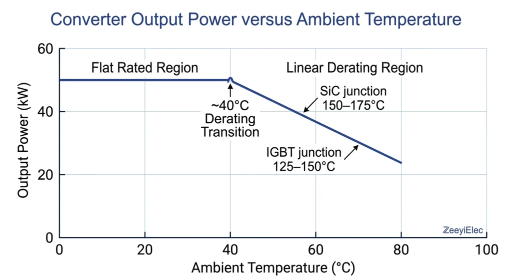
Figure 4. Thermal derating characteristic of the SST converter stage, illustrating output reduction above approximately 40°C ambient and the junction-temperature limits that govern cooling design.
Thermal Management and Converter Cooling Requirements
Converter losses concentrate in the semiconductor modules — far higher heat flux than transformer oil cooling. Junction limits bound the design, with output derating above roughly 40°C ambient common in tropical and desert sites. Forced-air and liquid cooling add maintenance items utilities do not carry: fans, filters, pumps need servicing, and heatsinks exposed to dust or salt degrade progressively.
Reliability, Service Life, and Spare-Parts Considerations
No fleet-scale reliability history exists for MV SSTs — read vendor claims against that absence. Two wear mechanisms are well understood: thermal and power cycling fatigue the semiconductor modules (power-cycling count, not calendar age, drives life), and DC-link electrolytic capacitors wear with design lifetimes of roughly 5–15 years depending on temperature, halving per 10°C rise. Spares must cover semiconductors, gate drivers, capacitors, cooling; obsolescence means a 10-year-old unit may face unmanufactured components.
Installation, Commissioning, and Maintenance Skill Requirements
Commissioning an SST is closer to a converter station than a transformer: protection coordination, grid-code compliance, insulation testing under converter-grade dv/dt, and electromagnetic compatibility (EMC) verification differ from 50/60 Hz routine testing. In service, maintenance shifts to power-electronics diagnostics, firmware, and control-network cybersecurity.
Expert Insight — O&M planning for SST assets
Budget cooling-system maintenance (fans, filters, pumps) as recurring cost.
Stock semiconductors, gate drivers, and DC-link capacitors; confirm the vendor’s obsolescence policy before ordering.
Plan firmware updates and control-network security reviews.
Standards and Qualification Landscape: What to Verify Before Specifying
The standards picture is the biggest procurement trap: conventional transformer standards are mature and enforced; SST-specific standards are still forming. Assuming “it’s a transformer, so IEC 60076 covers it” misses the power-electronics stages entirely.
IEEE and IEC Activity on Solid-State Transformers (with verification markers)
The IEC 60076 series governs power transformer design, insulation, and testing; an SST’s magnetic stage inherits transformer-type concerns, but converter stages sit outside that framework. IEEE 1547 applies where the SST interfaces distributed energy resources. Dedicated SST standardization is still in motion: IEEE has not yet published a dedicated solid-state transformer standard as of 2026 [VERIFY STANDARD: confirm whether an active IEEE SA project (PAR) for solid-state transformers exists in the IEEE standards project database before citing a designation — note that IEEE P2686 covers battery management systems, not SSTs], while IEC is drafting one — special working group IEC SC22F/ahG 6, “Performance of power electronic transformers for flexible transmission and distribution systems,” initiated in October 2020 and still unpublished (status per Tsinghua EIRI press release, September 2022; re-check on the IEC webstore). Re-verify at RFQ time.
Type Testing, Grid-Code, and Interconnection Compliance Considerations
Until a unified standard publishes, the buyer must impose their own checklist:
Insulation levels: confirm BIL and power-frequency withstand against the applicable ANSI or IEC system — typically 95 kV for 15 kV class, 125–150 kV for 25 kV class.
Converter-stage tests: efficiency across load range, harmonic injection, EMI/EMC, thermal cycling — none covered by transformer standards.
Grid-code compliance: fault ride-through, reactive capability, and interconnection rules (for example IEEE 1547 in DER applications), which vary by market.
Type versus routine test separation: demand explicit documentation of design-qualification versus production tests.
SST quotations arrive with inconsistent certificate packages because no unified standard exists — the checklist, not the marketing sheet, determines site acceptance. For the conventional side, the IEC specification cheat sheet for accessory procurement consolidates the standards applying to bushings, fuses, and cable accessories.
Should Your Project Choose SST or Conventional Technology? — Decision Guidance
Three screening questions settle most decisions. Does the application need bidirectional power flow, native DC output, or sub-cycle voltage regulation? Does the timeline tolerate emerging-technology risk and the absence of fleet reliability data? Can maintenance absorb power-electronics competencies? If any answer is “no,” the decision writes itself.
When SST Makes Sense vs When Conventional Distribution Transformers Remain the Practical Choice
An SST merits evaluation when the grid function demands what a passive transformer cannot deliver: EV fast charging with a 750–1500 V DC bus, DER-heavy feeders needing voltage control within a ±5% band and grid-forming capability, or power-quality mandates — where the premium buys avoided equipment: chargers, capacitor banks, regulation hardware.
Conventional technology remains the practical choice for most distribution projects: standard radial duty at 10–36 kV, cost-sensitive procurement, harsh environments where oil-cooled units and mature maintenance are proven, and schedules that cannot absorb prototype risk. For the accessory ecosystem supporting conventional transformers — bushings, tap changers, fuses, cable accessories — the engineering is mature. Our transformer accessories selection guide maps the decision framework, and our engineering team supports technical selection and RFQ preparation — send your project specs for feedback and quotation.
Frequently Asked Questions
What is a solid state transformer used for?
An SST converts and conditions power electronically, combining voltage transformation with active control. Today it appears mainly in grid-modernization, EV-charging, and renewable-integration demonstrations.
How efficient is a solid state transformer compared to a conventional transformer?
In published demonstrations, SST efficiency lands in the 96–99% band at full load versus roughly 98–99.5% for conventional units — it moves with load point, topology, and cooling.
What voltage levels do solid state transformers operate at?
Most distribution-focused designs take 10–36 kV MVAC input and deliver LVAC/LVDC output near 400 V to 1.5 kV; transmission-class prototypes extend higher.
Is a solid state transformer commercially available?
Yes, but narrowly: as of 2026 availability is limited to pilot-scale and niche deployments — EV charging, research platforms — not mainstream distribution stock.
How much does a solid state transformer cost?
Industry-reported figures typically run several times the price of a comparable conventional transformer, driven by power-electronics and cooling content — a premium that persists until volume scales.
Why would a utility choose an SST over a conventional transformer?
The value case rests on functions a passive transformer lacks — fast voltage control, bidirectional flow, DC output, harmonic filtering — and works only where they displace other equipment cost.
yoyo shi
Yoyo Shi writes for ZeeyiElec, focusing on medium-voltage accessories, transformer components, and cable accessory solutions. Her articles cover product applications, technical basics, and sourcing insights for global electrical industry buyers.





 English
 한국어
한국어 العربية
 Español
 हिन्दी
 தமிழ்
தமிழ் Deutsch (Sie)
 Français
 Português do Brasil
 Русский