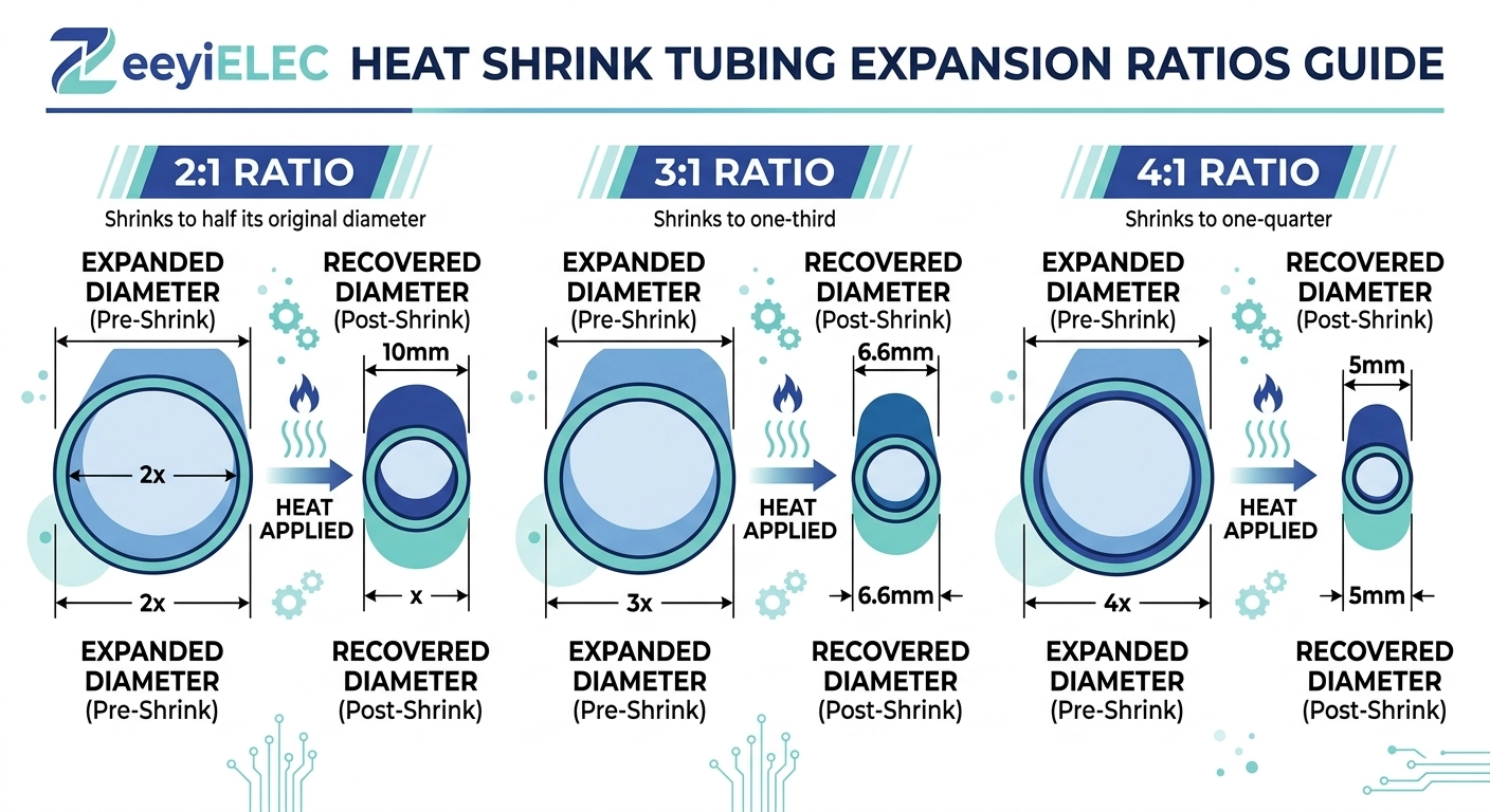
Heat shrink recovery ratio is the numeric relationship between a tube’s factory-expanded diameter and its final recovered (post-shrink) diameter after heat application. A 3:1 ratio means a tube expanded to 30 mm will recover to approximately 10 mm once fully shrunk and cooled, assuming unrestricted recovery against a smaller-diameter substrate. This single number determines how much diameter range a given kit can accommodate — which is why it sits at the center of every heat shrink accessory selection decision, alongside voltage class and conductor size.
The relationship is expressed as:
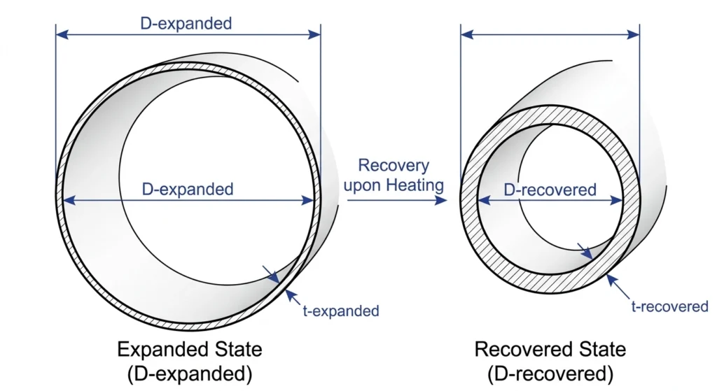
Recovery Ratio = Dexpanded ÷ Drecovered
For a tube with Dexpanded = 32 mm and Drecovered = 8 mm, the ratio is 4:1.
The mechanism behind this number traces back to material science, not arbitrary manufacturing choice. Cross-linked polyolefin tubing is manufactured in its recovered (small) diameter first, then heated, radially expanded, and rapidly cooled to lock the polymer chains in a temporarily stretched, amorphous state — a “shape memory” condition. This locked-in state is metastable: the material wants to return to its original molecular configuration but is kinetically prevented from doing so at room temperature. Applying heat in the field — typically in the 110°C–130°C range for standard polyolefin formulations — reintroduces enough thermal energy to unlock chain mobility, and the tube recovers toward its original, smaller diameter.
Recovery ratio is not the same as wall thickness recovery. Radial shrinkage and wall thickening happen together, but they’re governed by slightly different aspects of the polymer’s cross-link density and expansion history — a tube with a higher ratio doesn’t automatically produce proportionally thicker recovered walls.
From a field engineering standpoint, ratio matters because it defines the usable diameter window of a kit. A kit isn’t selected for a single cable OD; it’s selected to bridge the largest and smallest OD it will realistically encounter on a project, including OD variation between different cable manufacturers rated for the same voltage class. Getting this window wrong is one of the more common causes of on-site kit rejection, covered in detail below.
Cross-sectional view of a cross-linked polyolefin tube in expanded versus recovered state, illustrating the D-expanded to D-recovered relationship that defines recovery ratio.
Standard Recovery Ratios and Typical Applications
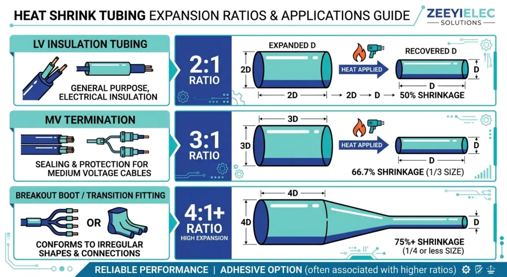
Heat shrink recovery ratio generally falls into three practical tiers, each suited to a different type of diameter variation encountered in cable accessory work. The ratio selected should match the actual spread between the largest and smallest OD the tube will need to seal — not just the nominal cable size on a datasheet.
2:1 Ratio
A 2:1 ratio tube expands to roughly twice its recovered diameter — for example, a tube recovering to 12 mm might ship expanded to 24 mm. This tier is typically used for LV insulation tubing, busbar protection, and applications where OD variation across the covered range is modest, such as single-cable-type projects with tight manufacturing tolerances. It’s less forgiving of cable-to-cable OD variation but offers a tighter, more predictable fit within its rated window.
3:1 Ratio
The 3:1 tier is the most commonly specified ratio for MV cable terminations and joints in the 10 kV and 20(24) kV class, where a single kit needs to accommodate moderate OD variation across different cable constructions rated for the same voltage class. A tube expanded to 30 mm recovering to 10 mm is a representative 3:1 example. This ratio balances field flexibility against wall-thickness consistency reasonably well, which is part of why it dominates general-purpose MV termination kit design.
4:1 Higher Ratios
Kits rated 4:1 or higher — occasionally reaching 5:1 or 6:1 in specialty products — are specified when a single kit must bridge a wide OD range, such as multi-core cable breakout boots, transition fittings between differently sized conductors, or projects where the same kit stocks across several cable gauges to reduce SKU count. The trade-off is mechanical: at higher ratios, recovered wall thickness and radial pressure become more sensitive to how close the installed OD sits to the kit’s rated minimum. Field experience across MV underground installations shows that kits pushed toward the low end of a high-ratio window can under-deliver radial pressure at the termination interface, which is why procurement teams should treat the rated range as a target window, not a hard limit to be tested at its edges.
A tiered comparison of 2:1, 3:1, and 4:1+ recovery ratios showing diameter transition range and typical LV, MV, and transition-fitting applications for each tier.
[Expert Insight]
A kit’s rated range is a design target, not a tolerance buffer — build margin into your own selection, don’t consume the manufacturer’s.
3:1 remains the default starting point for general MV termination work unless OD variation or a transition fitting pushes you toward 4:1.
Stocking one high-ratio SKU across several cable gauges can reduce inventory complexity, but only if radial pressure at the low end of the range has been verified, not assumed.
Selecting the correct recovery ratio starts with a measurement, not a catalog lookup. The process should follow a defined sequence rather than defaulting to whatever ratio the previous project used.
Step 1: Measure the Actual OD Range, Not the Nominal Size
Correctly matching heat shrink recovery ratio to cable OD starts by pulling OD across the full cable population, not the nominal datasheet figure. Cable OD varies by manufacturer, insulation thickness tolerance, and conductor stranding even within the same voltage class and cross-section. For a 10 kV XLPE cable nominally listed at 28 mm OD, actual measured values across different batches or suppliers can realistically span 26 mm–31 mm.
Step 2: Identify the Governing Diameters
Take the smallest OD in the population as the minimum recovered diameter the kit must reach, and the largest OD as the maximum diameter the kit must still grip with adequate wall thickness before shrinking. These two numbers — not the average — set the required window.
Step 3: Select the Ratio Tier That Covers the Window with Margin
Match the measured range against the kit’s rated expanded-to-recovered window, leaving margin rather than sizing to the exact edges. A kit rated for 3:1 with a recovered diameter of 10 mm and expanded diameter of 30 mm covers roughly a 10 mm–28 mm working range in practice, since a small allowance below the maximum expanded diameter is normal to preserve adequate recovery force. Selecting a kit whose minimum rated diameter sits right at the smallest cable in the batch leaves no tolerance for the next production run’s variation.
Step 4: Cross-Check Against Multi-Core or Transition Applications
For breakout boots or transition fittings joining conductors of different gauges within one assembly, the ratio requirement is set by the largest single diameter jump in the assembly, not the overall cable bundle OD — this is where 4:1 and higher ratios typically become necessary rather than optional.
Field experience on distribution-class underground projects shows that OD range is frequently underestimated at the RFQ stage because procurement pulls a single nominal OD from a cable datasheet rather than requesting the manufacturer’s tolerance band. This is one of the more common root causes traced during post-installation failure reviews, alongside kit mis-selection covered in ZeeyiElec’s Контрольный список по контролю качества монтажа вспомогательного оборудования среднего напряжения.
A selection workflow tracing measured minimum and maximum cable outer diameter through to the appropriate recovery ratio tier and kit configuration.
Field Consequences of Undersized vs. Oversized Ratio Selection
Heat shrink recovery ratio mismatches don’t always announce themselves at installation. Some fail visibly during staging; others pass initial inspection and surface as electrical failures months or years later.
Undersized Ratio: Fit and Staging Failures
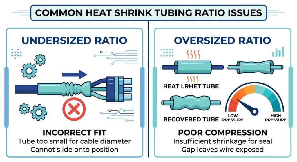
An undersized ratio — a kit whose maximum expanded diameter can’t clear the largest cable OD in the batch — typically fails at the staging step, before the crew ever applies heat. The tube either won’t slide over the prepared cable end at all, or it clears the straight cable run but can’t pass over a splice, connector lug, or stress cone shoulder further down the installation path. This is a visible, immediate failure that stops work rather than a latent defect, which is the main reason experienced field crews measure OD at the widest point of the assembly — not just the cable body — before selecting a kit.
Oversized Ratio: Insufficient Radial Pressure
The more consequential failure mode runs the other direction: a kit selected with a ratio well above what the actual cable OD requires. When a tube recovers onto a diameter that sits far above its rated minimum, the polymer stops contracting before it reaches its fully relaxed, high-pressure state. The result is a tube that looks fully shrunk — glossy surface, visible profile change, correct color — but is delivering meaningfully less radial pressure at the cable interface than a properly matched ratio would produce. Since radial pressure is what maintains the seal against moisture ingress and holds the stress-control geometry against the cable insulation, an under-pressured recovery can pass initial visual and even basic electrical acceptance testing, then develop moisture tracking or partial discharge activity over subsequent months of thermal cycling.
Radial pressure at the cable interface (Pr) is not linear with recovery — as recovered diameter approaches the tube’s rated minimum, Pr increases sharply; as recovered diameter approaches the tube’s rated maximum, Pr can fall below the level needed for reliable long-term sealing.
This failure mode is well documented in field diagnosis work: cable accessory failures attributed to “moisture ingress” or “tracking” during root-cause investigation frequently trace back to an oversized kit that passed installation without anyone recognizing the pressure deficit. For a structured approach to isolating this from other failure causes, see ZeeyiElec’s рабочий процесс диагностики отказов в полевых условиях.
Side-by-side comparison of an undersized recovery ratio causing a staging blockage versus an oversized ratio producing insufficient radial pressure after full recovery.
[Expert Insight]
A tube that “looks” fully shrunk isn’t proof of adequate radial pressure — visual gloss and color change alone don’t confirm the polymer reached its high-pressure recovered state.
Oversized-ratio failures tend to surface late, often during thermal cycling months after commissioning, which makes ratio selection an upstream reliability decision, not just a fit issue.
Always measure OD at the widest point of the full assembly — including splices, lugs, and stress cone shoulders — not just the straight cable run.
Installation and Staging Realities for High-Ratio Kits
Kits with a higher heat shrink recovery ratio demand more deliberate staging discipline than 2:1 or 3:1 products, since the larger expanded diameter means more material has to travel further to reach its recovered state, and the shrink process itself takes longer to complete evenly across the tube length.
Sequencing the Shrink for Stepped or Transitional Diameters
On breakout boots and transition fittings where a single kit spans a significant OD change — for example, transitioning from a 45 mm three-core cable jacket down to individual 18 mm core insulation — heat should be applied starting from the smaller-diameter end and worked progressively toward the larger end. This sequencing lets the material shrink and set on the tighter section first, anchoring the fitting before the wider section is brought down, which reduces the risk of the tube sliding or bunching mid-recovery on a long taper.
Heat Application Time and Temperature Control
Recovery time scales with wall thickness and ratio, not just tube diameter. A 4:1 kit typically requires longer, more evenly distributed heat exposure than a 3:1 kit of similar recovered size, since more material must be brought through the polymer’s crystalline melting transition before contraction can proceed uniformly. Field practice generally targets propane or electric heat guns delivering surface temperatures in the 110°C–130°C range, moving the flame or heat source continuously in a circular motion rather than holding it stationary, which prevents localized overheating that can scorch or embrittle one section while adjacent material remains under-recovered.
Verifying Full Recovery Before Sign-Off
Visual gloss change alone is not a reliable full-recovery indicator on higher-ratio kits, since the outer surface can appear fully shrunk while the material beneath — particularly at the tube’s thickest cross-section — has not fully contracted. Field crews commissioning MV terminations typically confirm recovery by checking that printed ratio indicator marks (where the manufacturer includes them) have converged to the specified spacing, and by confirming the tube conforms tightly to the underlying stress-control layer with no visible air gaps or wrinkling at the shoulder transitions.
Standards References and Verification for Recovery Ratio Claims
Heat shrink recovery ratio figures published on manufacturer datasheets are performance claims, not guarantees, unless tied to a specific test method and standard. Buyers evaluating heat shrink kits for MV cable accessory projects should verify how a supplier’s stated ratio was derived before treating it as a specification they can design around.
Heat shrink cable accessories for power distribution are generally evaluated against type-test programs covering dielectric withstand, thermal cycling, and mechanical performance of the recovered product — not the raw expansion ratio in isolation. Per IEC 60502-4:2023, Clause 6.2, component materials such as heat-shrink tubing are not individually required to undergo type testing; qualification is performed on the completed accessory assembly, with test methods specified in IEC 61442. Buyers should request the type-test report referenced on the datasheet rather than accepting the ratio number at face value, since a ratio measured on an unloaded tube in a lab environment can differ from recovered performance against an actual cable OD under field conditions.
For MV terminations and joints in the 10 kV and 20(24) kV classes, dielectric and thermal-cycling type tests are conducted on the fully recovered product at a specified installed diameter — meaning the ratio validated in testing corresponds to one point within the kit’s rated window, not the entire range. A kit tested at its rated minimum diameter and installed near its rated maximum in the field is operating outside the exact configuration that was type-tested, even though it remains within the manufacturer’s published range. Procurement teams sourcing for critical MV projects should ask suppliers which diameter within the rated window was used for type testing.
Buyers wanting to review standardized test methodologies for heat-shrinkable components independent of any single manufacturer’s claims can consult IEC 60502-4 cable accessories testing standards, which governs type-test requirements for power cable accessories rated 6 kV (Um = 7.2 kV) up to 30 kV (Um = 36 kV).
Sourcing Heat Shrink Kits with Verified Recovery Ratio Specs
Selecting the right recovery ratio only pays off if the kit’s actual performance matches what’s on the datasheet. ZeeyiElec manufactures heat shrink cable accessories across the 1 kV, 10 kV, 20(24) kV, and 35 kV classes, with ratio-matched kits engineered for termination, joint, and busbar protection applications spanning conductor cross-sections up to 800 mm².
For projects involving mixed cable batches, multi-supplier procurement, or transition fittings where OD range is wider than a single standard kit covers, our technical team can review your measured cable OD data — minimum and maximum, not just nominal size — and recommend the ratio tier and kit configuration that leaves adequate margin at both ends of the range.
We also provide type-test documentation on request, including the diameter configuration used during dielectric and thermal-cycling validation, so procurement and engineering teams can verify recovery ratio claims against the actual test conditions rather than the published range alone.
What recovery ratio is standard for medium-voltage heat shrink terminations?
3:1 is the most common ratio for MV terminations and joints in the 10 kV and 20(24) kV class, since it covers moderate OD variation across different cable manufacturers without pushing wall-thickness consistency to its limits. Projects with wider OD variation or transition fittings often move to 4:1 or higher instead.
Can a 3:1 kit be used where a datasheet specifies 4:1?
Only if the actual measured cable OD range falls fully within the 3:1 kit’s rated window with adequate margin — the ratio number itself isn’t the requirement, the diameter coverage is. Substituting a lower ratio without re-checking the OD range risks a staging failure if the largest cable in the batch exceeds the kit’s maximum expanded diameter.
Does recovery ratio affect dielectric performance or only mechanical fit?
Recovery ratio primarily governs mechanical fit and radial pressure, but radial pressure directly affects dielectric sealing performance, since insufficient pressure at the interface can allow moisture ingress that later leads to tracking. A kit installed near the low-pressure end of its rated range can meet initial acceptance testing while still carrying elevated long-term dielectric risk.
How is recovery ratio different from shrink temperature?
Recovery ratio describes how much the tube’s diameter changes between its expanded and recovered states, while shrink temperature is the heat input required to trigger that recovery, typically in the 110°C–130°C range for standard polyolefin. The two are related but independent — changing installation temperature within the recommended range doesn’t change the tube’s rated ratio.
What happens if the cable OD falls outside the kit’s rated range mid-run?
If OD exceeds the kit’s maximum expanded diameter, the tube generally can’t be staged over the cable at all, causing an immediate, visible installation stop. If OD falls below the kit’s rated minimum after full recovery, the tube can still appear shrunk but deliver reduced radial pressure, which is a harder failure to catch without dedicated inspection.
Do higher recovery ratios require different installation tooling?
Higher-ratio kits generally use the same heat guns and torches as lower-ratio products, but they typically require longer, more evenly distributed heat application to bring thicker recovered sections through full transition. Crews working frequently with 4:1 or higher kits often adopt a staged heating sequence — starting at the narrower end of a transition fitting — rather than relying on the same technique used for straightforward 2:1 or 3:1 tubing.
How should recovery ratio be verified before bulk ordering?
Request the supplier’s type-test report and confirm which diameter within the rated window was used for dielectric and thermal-cycling validation, rather than accepting the published expanded-to-recovered range alone. Cross-checking this against your project’s actual measured cable OD range — not the nominal datasheet figure — is the most reliable way to confirm the kit will perform as tested once installed.
йойо ши
Йойо Ши пишет для ZeeyiElec, специализируясь на аксессуарах для среднего напряжения, компонентах трансформаторов и кабельных аксессуарах. В ее статьях рассказывается о применении продукции, технических основах, а также об особенностях поиска поставщиков для глобальных покупателей электротехнической промышленности.





 English
 한국어
한국어 العربية
 Español
 हिन्दी
 தமிழ்
தமிழ் Deutsch (Sie)
 Français
 Português do Brasil
 Русский