O que é uma faixa de derivação e por que os transformadores de distribuição precisam dela
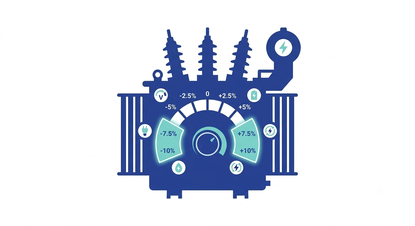
A faixa de derivação em projetos de transformadores de distribuição determina em que medida um comutador de derivação pode corrigir a tensão secundária à medida que as condições de alimentação variam. Na maioria dos transformadores de distribuição, essa faixa abrange de ±5% a ±10% da tensão nominal, dividida em um número fixo de posições de derivação discretas, em vez de um ajuste contínuo. O mecanismo define uma correção de relação fixa que permanece ativa até a próxima interrupção programada — ele não regula a tensão dinamicamente sob carga, o que é a função de um comutador de derivações em carga em transformadores de potência.O enrolamento primário inclui vários pontos de derivação, cada um conectando um número ligeiramente diferente de espiras. A seleção de uma derivação mais próxima do início ou do fim do enrolamento altera a relação de espiras efetiva, aumentando ou diminuindo a tensão secundária em um incremento conhecido. A ±5% A janela normalmente oferece cinco posições em 2.5% etapas; a ±10% A janela costuma exibir cinco posições ao longo de 5% etapas, embora isso varie de acordo com o fabricante e a classe de kVA.
Um transformador próximo à subestação geralmente apresenta maior estabilidade de tensão do que um localizado no final de um longo alimentador, onde a queda de tensão sob carga de pico pode levar a tensão secundária para fora dos limites aceitáveis sem um ajuste de compensação. Errar nesse cálculo na fase de especificação não pode ser corrigido em campo — as derivações do enrolamento são fixadas na fabricação; portanto, uma faixa de valores subdimensionada não deixa margem para as condições reais do local, enquanto uma superdimensionada acrescenta complexidade e custo desnecessários ao enrolamento.
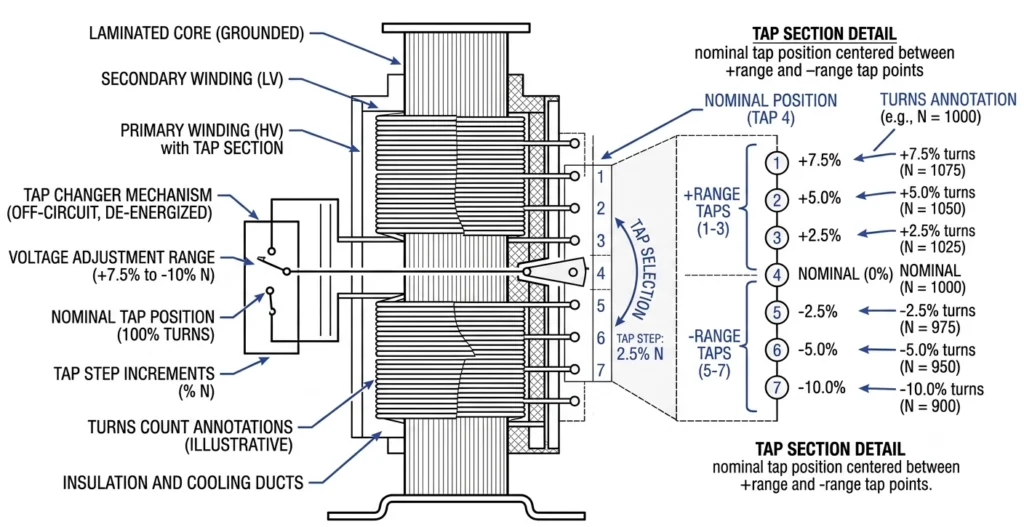
Cada ponto de derivação conecta um número diferente de espiras do enrolamento, permitindo que o comutador altere a relação efetiva de espiras em incrementos percentuais fixos.
Intervalo x Passo x Número de posições
Intervalo é a janela percentual total (por exemplo, ±5%). O passo é o incremento entre posições adjacentes (por exemplo, 2.5%). A contagem de posições é o que os dois, juntos, produzem — um ±5% janela em um 2.5% Essa etapa resulta em cinco posições.
Dados essenciais que determinam a janela de ajuste necessária
É necessário coletar quatro categorias de dados antes que qualquer valor percentual seja incluído em uma especificação.
Variação da tensão no lado da alimentação
A tensão no lado primário de um ramal de distribuição pode oscilar em ±5% para ±8% da tensão nominal ao longo de um ciclo de carga diário, sendo maior em ramificações com comutação industrial intensa ou bombeamento sazonal. Esse valor deve ser obtido a partir de uma medição real da tensão no ponto de conexão, e não de um valor presumido.
Impedância e queda de tensão do transformador
A impedância (Z%) afeta diretamente a queda de tensão no lado secundário sob carga, independentemente da variação no lado primário. Um transformador de distribuição com impedância tipicamente na 4% para 6% A faixa apresenta uma queda secundária mensurável próxima à carga total, e isso se soma — e não substitui — à margem que a janela de derivação deve cobrir.
ΔVsecundário ≈ Icarregar × Z% (como fração da tensão nominal, ajustada pelo fator de potência)
Consulte a impedância no relatório de teste de fábrica, e não o valor padrão do catálogo, já que os valores reais variam dentro da tolerância de fabricação.
Perfil de carga e meta de regulação
O perfil de carga determina a magnitude da queda que ocorre entre as condições de carga leve e de pico. A meta de regulação — comumente ±5% do valor nominal — define qual faixa secundária é aceitável no lado de saída. Um alimentador com carga industrial variável precisa de uma janela diferente daquela que atende a uma carga residencial estável com variação primária idêntica, pois a oscilação no lado secundário se acumula de maneira diferente.
[Expert Insight].
Utilize o relatório de teste de fábrica para a impedância, e não o valor padrão indicado na placa de identificação
Uma pesquisa que abranja apenas os horários fora do pico subestima a variação real — insista em um ciclo completo de demanda de pico
Ponderar a entrada do perfil de carga em função da queda transitória para locais com grande corrente de partida do motor
Método passo a passo para calcular a janela de ajuste
Etapa 1 — Coletar dados do levantamento de tensão
Registre os valores mínimos e máximos da tensão primária durante um período representativo. Exemplo: tensão nominal de 11 kV, variação registrada entre 10,45 kV e 11,55 kV — a ±5% variação.
Etapa 2 — Determinar o desvio no pior cenário
Some a queda esperada no lado secundário, causada pela impedância sob carga máxima, ao desvio maior no lado primário. Em 4.5% impedância e operação quase em carga total, essa queda se agrava com a condição de baixa tensão, uma vez que ambos levam a tensão secundária na mesma direção.
Etapa 3 — Converter para a porcentagem exigida
Intervalo exigido (%) ≈ Desvio da tensão primária (%) + queda de impedância no pior caso (%) na carga máxima, avaliado separadamente para as condições de baixa tensão e alta tensão
Aqui, um 5% condição de baixa tensão, além de um 4.5% a queda de impedância indica ±10% em vez de um isqueiro ±5% unidade.
Etapa 4 — Arredondar para os valores padrão
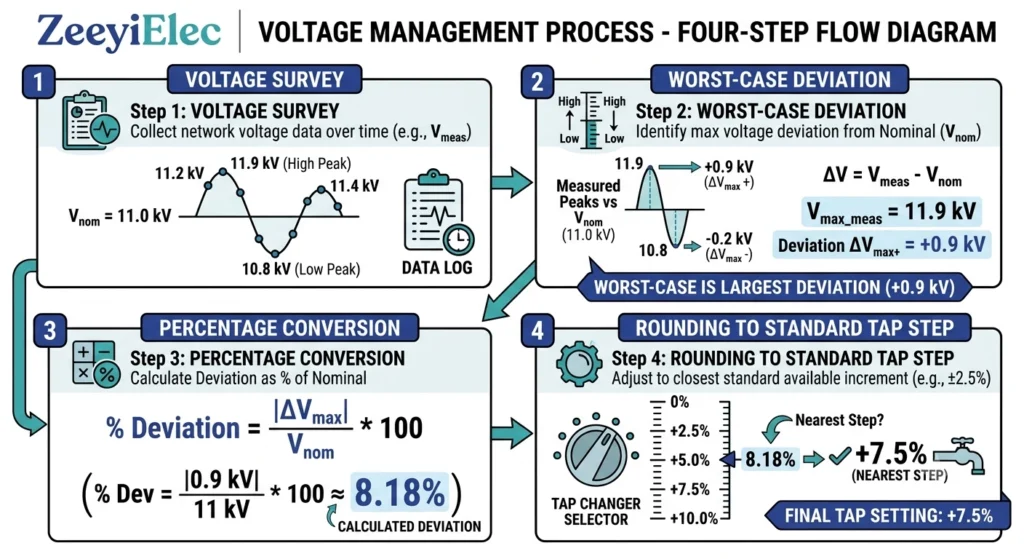
Incrementos padrão — geralmente 2.5% — o que significa que a necessidade calculada de 8,7% deve ser arredondada para ±10% em 2.5% valores inteiros, em vez de uma fração fora do padrão. Em projetos de alimentação rural, essa etapa de arredondamento é frequentemente ignorada, o que obriga o fornecedor a entrar em contato novamente para solicitar esclarecimentos e acrescenta mais uma etapa ao ciclo de aquisição.A sequência de cálculo da faixa de derivação vai desde os dados do levantamento de tensão, passando pelo cálculo da queda de impedância, até a seleção final da derivação arredondada.
As especificações e a terminologia relativas à gama de torneiras estão formalmente definidas em IEC 60076-1, a norma geral para transformadores de potência, que abrange a classificação, as especificações dos enrolamentos com derivações e os requisitos de identificação na placa de identificação.
Valores típicos por cenário de aplicação
Aplicações urbanas/de alimentação de curta distância
Variação dentro de ±2,51 TP3T para ±5% é comum nas proximidades de uma subestação, em ramificações curtas e bem reguladas. A ±5% janela em um 2.5% Essa etapa geralmente é suficiente.
Aplicações em áreas rurais/alimentadores de longa distância
Oscilações de ±8% para ±10% são comuns no final de linhas longas, agravadas pela queda de impedância durante os picos sazonais de carga. ±10% essa é a referência comum; algumas concessionárias especificam janelas personalizadas mais amplas para alimentadores marginais.
Alimentadores para setores industriais e com grande uso de energia renovável
O fluxo reverso de energia proveniente da geração distribuída pode elevar a tensão local acima do valor nominal durante períodos de baixa demanda, enquanto a partida de motores causa quedas transitórias de tensão. ±10% é típico, às vezes com uma distribuição assimétrica em favor do lado de alta tensão.
Tabela: Valores típicos por cenário
Cenário
Variação primária típica
Intervalo comum
Etapa comum
Urbano / alimentador de curta distância
±2,5%–5%
±5%
2.5%
Alimentador rural / de longo alcance
±8%–10%
±10%
2.5%–5%
Setor industrial / com grande participação de energias renováveis
Variável, bidirecional
±10%
2.5%
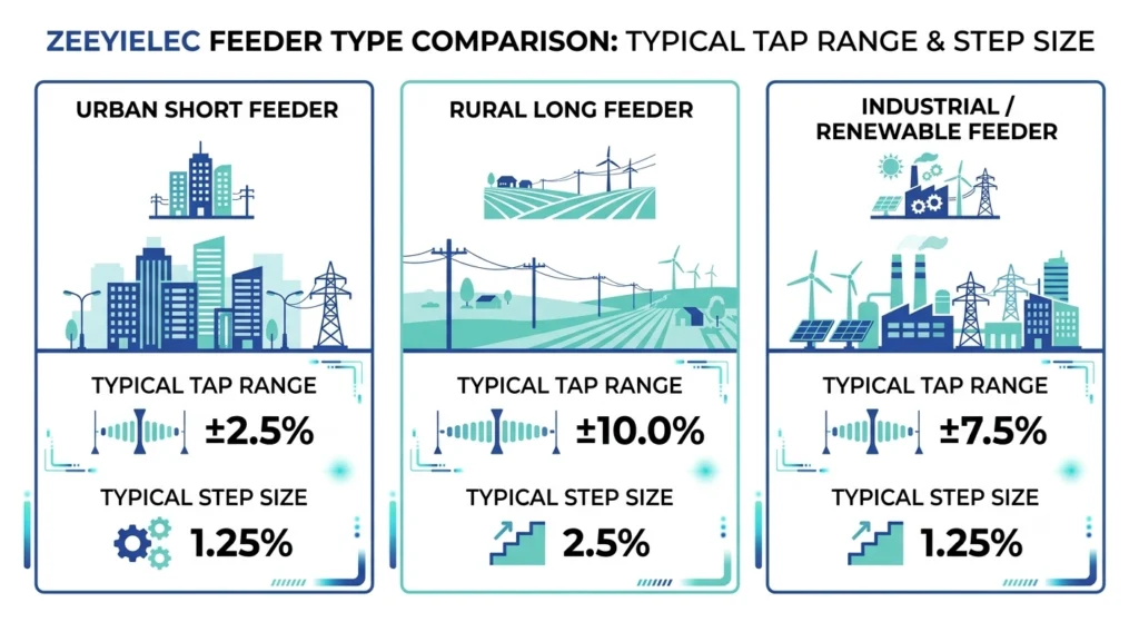
Os requisitos típicos de alcance das torneiras variam de acordo com o tipo de alimentador, desde intervalos mais restritos em áreas urbanas até cenários mais amplos em áreas rurais e de geração industrial.
Essas faixas pressupõem uma construção padrão do comutador de derivação fora de circuito; perfis de tensão atípicos ainda exigem o cálculo completo.
Condições de campo que aumentam ou diminuem a amplitude da janela
Segmentos vulneráveis da rede e oscilações sazonais na demanda
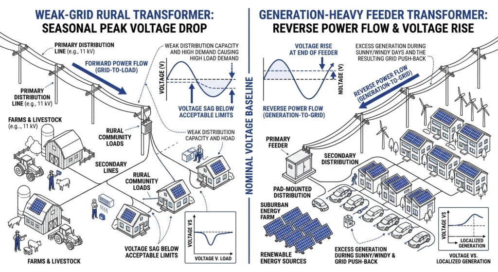
Um segmento “fraco” — com alta impedância de fonte em relação à carga, geralmente na extremidade mais distante de uma longa linha — pode apresentar oscilações sazonais que excedem 10% mesmo quando a média anual parece estar mais próxima de 6% para 7%. A dimensionação com base no pico sazonal mais intenso já registrado, e não na média anual, evita que a capacidade seja subestimada.
Geração Distribuída e Fluxo Reverso de Energia
Quando a produção das fontes de geração distribuída excede o consumo local, a energia retorna para a subestação e pode elevar a tensão secundária acima do valor nominal — às vezes em 5% ou mais. Isso inverte a preocupação tradicional com as linhas de alimentação rurais, nas quais o risco está quase sempre relacionado à baixa tensão, e não à alta.Segmentos com rede frágil ampliam a faixa de derivação devido à queda sazonal de tensão, enquanto alimentadores com alta carga de geração exigem margem para o aumento de tensão causado pelo fluxo reverso.
[Expert Insight].
Em segmentos da rede com baixa capacidade, dimensionar com base no pico sazonal mais intenso, e não na média anual
As redes de distribuição com grande carga de geração precisam de margem para o aumento da tensão, e não apenas para a queda
Compare com os dados de uma temporada anterior quando um único período de levantamento não for confiável
Erros comuns ao definir a janela de ajuste
Especificação insuficiente
Definir corretamente a faixa de derivação para projetos de transformadores de distribuição já na fase de especificação evita dois erros recorrentes. Um projeto dimensionado apenas para um 5% oscilação primária sem o adicional 3% para 5% A queda típica geralmente ocorre em um intervalo de tempo muito curto para atender à demanda de pico — e as posições das válvulas não podem ser corrigidas após a fabricação.
Especificação excessiva
Uma versão mais sutil desse erro é copiar um valor “padrão” de um projeto anterior sem refazer o cálculo para o novo local — dois alimentadores com a mesma tensão nominal podem apresentar perfis de variação muito diferentes. A faixa de derivação e a notação do fator de derivação são formalmente definidas na Cláusula 5 da norma IEC 60076-1, enquanto o método para converter casos de carga e variação da tensão de serviço em uma faixa de derivação específica é abordado na norma IEC 60076-8; nenhuma das normas prescreve uma faixa “correta” universal; portanto, os valores de um projeto anterior devem sempre ser verificados novamente com base nos dados atuais do local antes de serem reutilizados.
Como definir corretamente as especificações na sua solicitação de cotação
Um item de cotação bem estruturado deve incluir o valor calculado (por exemplo, ±10%), a etapa preferida (geralmente 2.5%), bem como os dados subjacentes — tensão primária nominal, variação registrada e impedância — para que a equipe de engenharia do fornecedor possa identificar incompatibilidades antes do início da fabricação.
O contexto do local é tão importante quanto os números: observe se a instalação está localizada em um segmento fraco da rede, se sofre oscilações sazonais ou se está conectada a geração distribuída, pois isso orienta ajustes que um simples valor percentual não transmitiria. Para projetos que abrangem várias famílias de acessórios, esses dados devem ser especificados juntamente com a classe de tensão das buchas, o BIL e os parâmetros de coordenação de fusíveis, em vez de serem apresentados separadamente. Projetos que também especifiquem componentes do lado do cabo podem fazer referência a Linha de acessórios para cabos da ZeeyiElec para orientação sobre a seleção paralela durante o mesmo ciclo de solicitação de cotação.
Qual é a faixa típica de derivações para projetos de transformadores de distribuição?
A maioria dos transformadores de distribuição utiliza uma faixa entre ±5% e ±10% da tensão nominal, dependendo da variação da tensão primária e da impedância no local específico. O fornecimento estável em linhas curtas tende a ficar na extremidade mais estreita; os alimentadores rurais longos normalmente requerem a faixa mais ampla.
Quantas posições de derivação possui um comutador de derivação fora de circuito padrão?
As configurações padrão geralmente oferecem cinco posições, embora o número dependa da combinação entre a faixa total e o tamanho do passo selecionado. Uma janela de ±5% com um passo de 2,5% e uma janela de ±10% com um passo de 5% costumam produzir cinco posições com incrementos de tensão diferentes.
É possível alterar a faixa de derivação após a fabricação de um transformador?
Não — as posições das válvulas são fixadas na fase de enrolamento; portanto, uma janela com dimensões menores ou maiores do que o necessário não pode ser corrigida no local sem que seja necessário reenrolar ou substituir a unidade. É por isso que o cálculo precisa ser feito com precisão antes da emissão do pedido de compra.
A faixa de derivação afeta a impedância ou as perdas do transformador?
Isso não altera diretamente a impedância nominal, mas uma janela mais ampla com mais posições pode introduzir pequenas variações na impedância entre as configurações. Essas variações são geralmente mínimas para unidades padrão da classe de distribuição, mas vale a pena confirmar com o fornecedor no caso de requisitos de regulação rigorosos.
Como o perfil de carga influencia a faixa de derivação necessária?
Uma linha de alimentação com grandes oscilações entre a carga mínima e a carga máxima agrava a variação no lado primário com a queda de impedância, ampliando a janela necessária para além do que a variação primária por si só sugeriria. Perfis estáveis e previsíveis normalmente permitem uma janela mais estreita do que a demanda industrial ou agrícola sazonal.
O que acontece se a faixa de tensão for muito restrita para as condições de tensão do local?
A tensão secundária fica fora dos limites aceitáveis de regulação nas condições mais adversas, sem que haja margem disponível para compensação. A correção geralmente implica aceitar um funcionamento fora da tolerância até a próxima troca do transformador.
A faixa de derivação é a mesma coisa que regulação de tensão?
Não — trata-se de uma correção fixa, selecionada manualmente durante o comissionamento ou em paradas programadas, enquanto a regulação de tensão normalmente se refere ao controle dinâmico, sensível à carga, em comutadores de derivação em carga utilizados com transformadores de potência. As unidades fora de circuito utilizam a janela fixa para corrigir condições conhecidas e relativamente estáveis, em vez de flutuações momentâneas.
yoyo shi
Yoyo Shi escreve para a ZeeyiElec, com foco em acessórios de média tensão, componentes de transformadores e soluções de acessórios para cabos. Seus artigos abrangem aplicações de produtos, fundamentos técnicos e percepções de sourcing para compradores do setor elétrico global.





 English
 한국어
한국어 العربية
 Español
 हिन्दी
 தமிழ்
தமிழ் Deutsch (Sie)
 Français
 Português do Brasil
 Русский