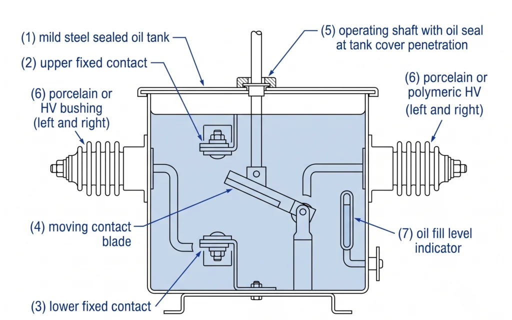
An oil immersed loadbreak switch interrupts load current while the circuit remains energized, using dielectric oil simultaneously as the arc-quenching medium and the primary insulating barrier between live parts and ground. Unlike vacuum interrupters or SF₆ gas switches, this design relies on the rapid decomposition and recombination of hydrocarbon molecules under arc energy to extinguish the switching arc within microseconds of contact separation. This construction remains cost-effective for distribution networks rated from 11 kV to 36 kV, particularly in markets where transformer oil infrastructure is established and maintenance personnel are familiar with oil handling procedures.
What Is an Oil Immersed Loadbreak Switch? Construction and Arc-Quenching Mechanism
Annotated cross-section of a distribution-class oil immersed loadbreak switch illustrating the sealed oil tank, moving contact blade, arc quenching chamber, operating shaft seal, and polymeric bushing entry geometry.
How Oil Serves as Arc-Quenching Medium
When the moving contact separates under load, the electrical arc instantly vaporizes a thin layer of surrounding oil, generating a high-pressure hydrogen-rich gas bubble. This local pressure rise, typically reaching several atmospheres within the interrupter chamber, forces fresh oil across the arc column at the current zero crossing, cooling the arc channel and suppressing re-ignition. The effectiveness of this mechanism depends directly on oil dielectric breakdown strength, which in service-ready condition should measure no less than 30 kV across a 2.5 mm gap, with new oil typically exceeding 50 kV under the same test geometry.
The sealed tank fabricated from mild steel plate or cast iron depending on manufacturer tier serves as both structural housing and oil containment boundary. Internal fixed contacts are typically copper alloy with silver or tungsten-copper facing at the arc-interrupting surface, resisting erosion over the rated mechanical endurance cycle, commonly specified at 1,000 to 2,000 operating cycles for distribution-class devices.
The external operating mechanism transmits torque through a sealed bearing or stuffing box to the internal contact blade. This shaft penetration point is a known ingress risk in aged equipment; field commissioning teams routinely inspect seals for oil weeping before energization, particularly on units stored horizontally during shipping.
Dielectric Performance: Oil Breakdown Voltage and Insulation Coordination
For a 24 kV rated switch, the lightning impulse withstand level (LIWL) is typically specified at 125 kV peak, while the one-minute power-frequency withstand voltage is commonly 50 kV rms. Bushing creepage distance for outdoor-rated units in a moderate pollution environment (IEC pollution severity class III) is generally no less than 25 mm/kV of rated voltage, placing the minimum creepage for a 24 kV bushing at approximately 600 mm. Procurement engineers specifying units for coastal or industrial-contamination zones should request class IV creepage geometry from the outset, as retrofitting bushings post-delivery is rarely practical.
For a broader view of how bushings interact with the overall transformer accessory system, the transformer accessories product overview provides configuration context across voltage classes.
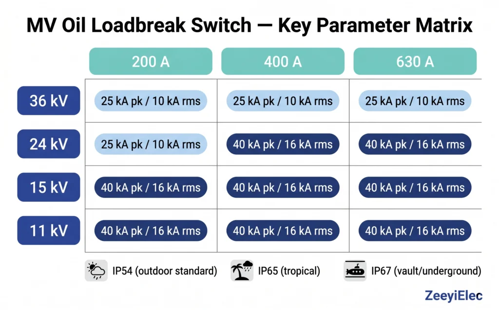
Critical Technical Parameters for MV Loadbreak Switch Selection
Selecting an oil-type switching device on voltage class alone produces mismatches that surface during factory acceptance testing or after energization. Four parameter groups govern compatibility: voltage class and current rating, fault current withstand capability, mechanical and electrical endurance, and environmental classification. Each carries independent consequences if under-specified.
Specification parameter matrix for oil immersed loadbreak switches: voltage class (11–36 kV) cross-referenced against rated current (200–630 A) and short-circuit withstand current (kA), with indicative IP rating classification by installation category.
Voltage Class and Rated Current Ranges
Oil immersed loadbreak switches for medium-voltage distribution are manufactured across four principal voltage classes: 11 kV, 15 kV, 24 kV, and 36 kV, corresponding to system nominal voltages of 10 kV, 13.8 kV, 22 kV, and 33 kV respectively. Rated continuous current follows a standard stepped progression 200 A, 400 A, and 630 A with 630 A representing the practical ceiling for oil-type designs before thermal management inside the sealed tank becomes a limiting constraint. Engineers should confirm that the rated current exceeds the maximum continuous load current by a margin of at least 20–25%, accounting for load growth over the asset’s intended 20–30 year service life.
Short-Circuit Making and Breaking Capacity
Short-circuit withstand is the parameter most frequently under-specified by procurement teams working from single-line diagrams without updated fault level studies. An oil-filled MV switch is not a fault-interrupting device it must close onto a fault without contact welding and withstand the thermal and electromagnetic stress of fault current until an upstream protective device clears.
Peak making capacity for distribution-class devices is typically rated at 25 kA peak or 40 kA peak depending on the network fault level, with a corresponding short-time withstand current (Icw) of 10 kA rms or 16 kA rms for 1 second. Specifying a device with Icw below the prospective fault current at the installation point risks contact fusion on the first fault event a failure mode that renders the switch inoperable and may require transformer outage for replacement.
Mechanical and Electrical Endurance Ratings
Mechanical endurance is typically rated at 2,000 no-load operations for standard distribution service. Electrical endurance operations performed at rated load current is lower: commonly 200 to 500 operations, reflecting arc erosion at each interruption. For ring main unit applications with frequent sectionalizing, specifying a device at the upper endurance band avoids premature contact replacement within the first maintenance cycle.
Environmental Classification: IP Rating and Altitude Derating
Tank-mounted units in outdoor configurations require a minimum ingress protection rating of IP54, while units in underground vaults or high-humidity tropical environments are more appropriately specified at IP65 or IP67. Above 1,000 m, reduced air density degrades external insulation performance; units intended for altitudes between 1,000 m and 4,000 m typically require explicit high-altitude type testing or voltage class uprating by one step, for example, specifying a 36 kV class unit for a 24 kV system at 3,000 m elevation.
Field teams commissioning units at elevation consistently report corona activity on standard-altitude-rated bushings below nameplate withstand level when ambient air pressure drops below approximately 90 kPa. Confirming altitude correction with the manufacturer before purchase order is standard practice on hydropower and mountain substation projects.
Oil-type switching devices are not fault-interrupting; always verify prospective fault current at the installation point against the I<sub>cw</sub> rating before specifying.
A 20–25% current margin above maximum continuous load current is minimum, not target for 20–30 year asset life planning.
Altitude derating is frequently omitted on highland grid projects; one voltage class uprating above 1,000 m is a low-cost insurance measure.
IP67 specification adds marginal cost at order stage but eliminates tank-seal-related oil contamination failures that cost 10–15× more to remediate in the field.
Selection Criteria Framework Before Evaluating Any Brand
Brand reputation and price are late-stage filters. The earlier work is confirming architectural compatibility with your network topology, transformer interface, applicable standards, and total cost model. Engineers who skip this framework and proceed directly to brand shortlisting frequently discover incompatibilities after samples arrive on site.
Network Topology Fit: Ring Main Unit vs. Radial Feeder
RMU service typically involves infrequent switching, annual sectionalizing during maintenance cycles placing endurance requirements at the lower end of the specification range. Radial feeder applications with automatic reclosing or frequent load transfer operations accumulate electrical endurance cycles significantly faster, potentially reaching 200 load-current operations within five to eight years on active feeders. The physical form factor differs correspondingly: RMU-integrated switches have fixed flange interfaces, while pole-mount or pad-mount standalone switches require field-adaptable cable termination and a robust external operating mechanism accessible from ground level.
Interoperability with Existing Transformer Accessories
Flange bolt patterns vary between transformer manufacturers, a 150 mm bolt circle diameter on one transformer design may be incompatible with a switch supplied to a 130 mm pattern without an adapter plate. Requesting certified dimensional drawings from both the transformer manufacturer and the switch supplier before purchase order approval is not optional on retrofit projects.
Electrical interoperability extends to insulation coordination margin. Connecting a dielectric oil switch rated at 24 kV to a transformer whose HV bushing is also rated 24 kV leaves zero margin for switching overvoltages; specifying the switch one voltage class higher 36 kV, provides the creepage geometry needed to accommodate transients without risk of external flashover. Both transformer and cable accessory interface requirements are covered in the cable accessories overview for projects involving complete MV network builds.
Standards Compliance Mapping
IEC 62271-103 governs AC switches rated above 1 kV and up to 52 kV, defining the type test sequence load current switching, fault making, and short-time withstand, that a compliant device must pass. Regional projects frequently add utility-specific dielectric test voltages, seismic qualification, or tropical climate endurance testing on top of the IEC baseline. Confirming that a supplier’s type test certificate covers the exact voltage and current rating being procured, not a higher-rated variant prevents a common documentation gap where a 36 kV certificate is presented for a 24 kV procurement.
Total Cost of Ownership: First Cost vs. Oil Maintenance Interval
A lower first-cost unit with a 3-year oil testing interval generates higher lifecycle cost than a premium unit rated for 5-year intervals across a 30-asset feeder network. Oil dielectric strength testing costs between USD 80 and USD 200 per unit per event depending on laboratory location and mobilization. Across 30 units over a 25-year asset life, a 2-year difference in testing interval accumulates to a meaningful operations budget difference before accounting for oil replacement or unit changeout costs.
The transformer accessories RFQ checklist provides a structured parameter framework for capturing these lifecycle variables before supplier quotations are requested.
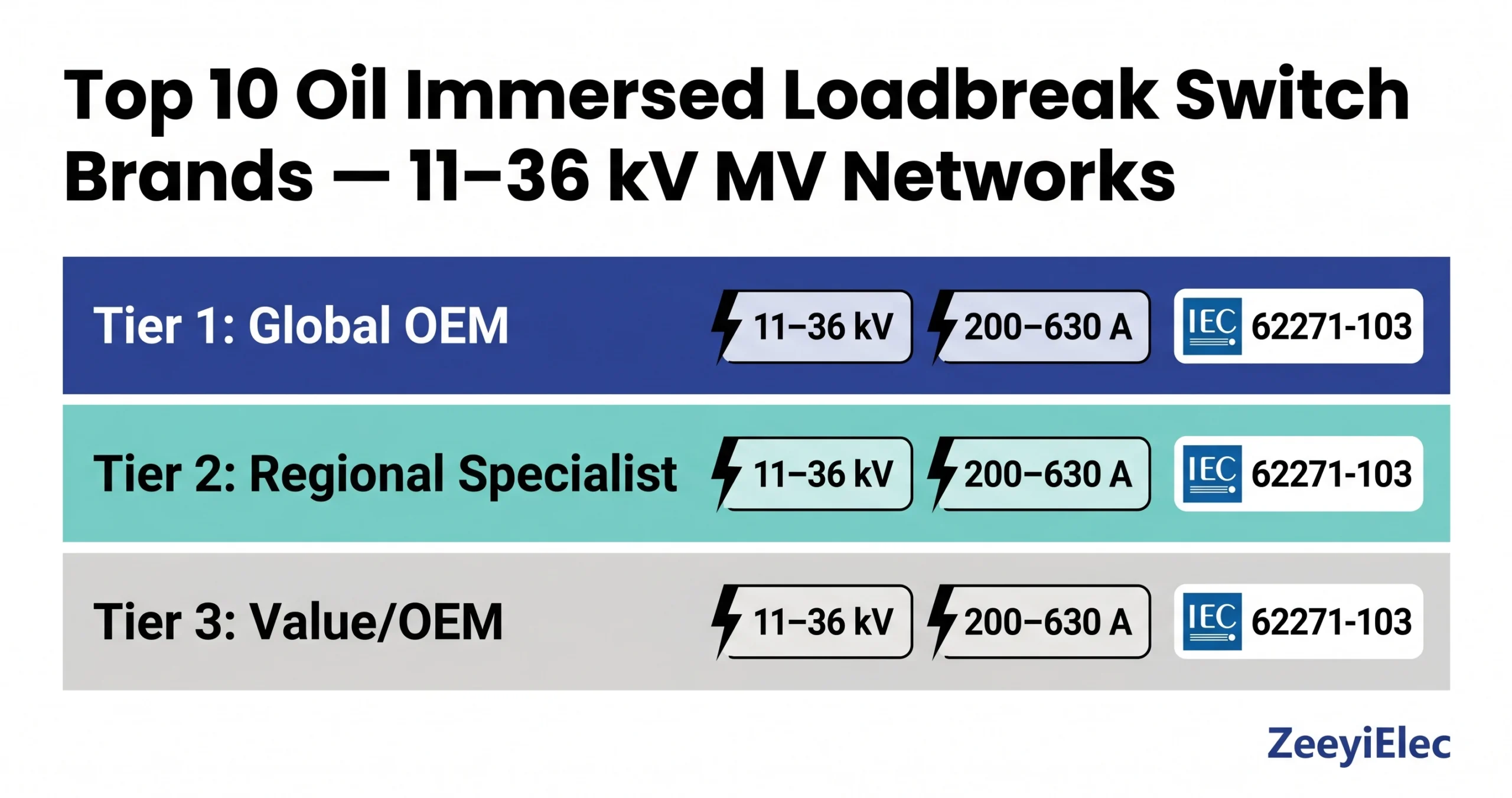
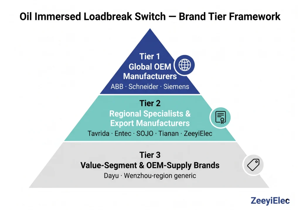
Top 10 Oil Immersed Loadbreak Switch Brands — Comparative Overview
No single brand leads across all procurement criteria simultaneously. The framework below organizes representative manufacturers into three tiers based on market positioning, type test documentation depth, and geographic supply reach, not a ranked performance judgment. Each entry requires independent verification of current product range, test certificates, and regional distributor support before RFQ issue.
Manufacturer tier classification for oil immersed loadbreak switch procurement: Tier 1 global OEMs, Tier 2 regional specialists, and Tier 3 value-segment suppliers differentiated by IEC type test documentation depth, supply reach, and price-to-specification positioning.
Comparison Table: Representative Brands by Key Parameters
Brand
Tier
Voltage Range
Rated Current
Notable Strength
Primary Market
ABB (Hitachi Energy)
1
11–36 kV
200–630 A
Full IEC 62271-103 type test portfolio; RMU integration
Global
Schneider Electric
1
11–36 kV
200–630 A
SM6 / Ringmaster RMU ecosystem; tropical variants
Global
Siemens Energy
1
11–36 kV
200–630 A
NXPLUS switchgear integration
Europe, Americas
Tavrida Electric
2
11–35 kV
400–630 A
Harsh environment; recloser combination
CIS, Africa, Asia
Entec Electric
2
11–36 kV
200–630 A
Utility-grade type testing; SEA grid projects
Asia-Pacific
SOJO Electric
2
11–36 kV
200–630 A
Export-oriented; IEC-compliant designs
Africa, Middle East
Tianan Electric
2
12–40.5 kV
200–630 A
China utility supply; growing export documentation
All values are representative published ranges. Verify current datasheets directly with each manufacturer before procurement.
Tier 1: Global OEM Manufacturers
ABB (Hitachi Energy), Schneider Electric, and Siemens Energy hold complete IEC 62271-103 type test portfolios across the full 11 kV–36 kV range, with established global spare parts networks and documented tropical and seismic variants. Their products are frequently factory-assembled within ring main units rather than supplied standalone, which simplifies substation procurement but reduces flexibility for retrofit or pole-mount applications. Lead times for non-standard configurations typically run 12–20 weeks ex-factory, and minimum order quantities for project-specific variants can present obstacles for projects with fewer than 20 units per line item.
Tier 2: Regional Specialists and Export-Oriented Manufacturers
Tier 2 manufacturers compete on a price-to-specification ratio that Tier 1 suppliers structurally cannot match for standard-configuration orders. The critical differentiator within Tier 2 is documentation depth: manufacturers capable of supplying IEC 62271-103 type test reports, routine test certificates per unit, and export documentation packages represent meaningfully lower procurement risk than those without traceable test evidence. Field experience on African and Southeast Asian grid expansion projects consistently shows that Tier 2 units with complete documentation outperform undocumented alternatives in total project risk terms, documentation gaps create customs clearance delays and utility acceptance problems that erode any first-cost advantage. For a detailed view of what export documentation should accompany an electrical accessory order, the export documentation checklist covers the full package required for international shipments.
Tier 3: Value-Segment and OEM-Supply Brands
Tier 3 covers manufacturers supplying products primarily as OEM components to transformer assemblers or as cost-driven replacements for non-critical radial feeders. Type test coverage is variable, some manufacturers hold partial reports covering only the most commonly ordered voltage class. Short-circuit making capacity claims warrant independent verification; published values of 25 kA peak should be confirmed against actual test certificates rather than catalog specifications alone. Tier 3 products are not categorically unsuitable: on accessible rural radial feeders where fault levels are demonstrably below 10 kA and annual oil checks are feasible, a well-specified unit with verified routine test certificates delivers acceptable service life at significantly reduced capital cost.
Authority reference: IEC 62271-103:2011 establishes the type test regime — including load current switching, fault making capacity verification, and short-time withstand — that differentiates documented from undocumented claims across all three tiers. Request the specific edition and amendment status of test certificates presented by suppliers, as older certificates may not reflect current edition requirements.
Expert Insight
Never accept a type test certificate for a higher voltage class as coverage for a lower-rated procurement; IEC 62271-103 type tests are rating-specific.
Documentation completeness, routine test certificate per unit, not just one type test for the batch is the single most practical differentiator between Tier 2 manufacturers at similar price points.
For export projects requiring Letters of Credit, confirm that the supplier’s test certificates carry an accredited laboratory stamp acceptable to the receiving country’s utility; self-issued factory certificates are frequently rejected at utility acceptance stage.
Field Performance and Installation Realities Across Brand Tiers
Comparison tables describe laboratory performance. Field conditions introduce variables no catalog anticipates: humidity cycles, shipping-induced oil contamination, operating mechanism corrosion, and maintenance teams working without the original installation manual. Two field scenarios illustrate where brand tier translates and where it does not into operational outcome.
Commissioning in High-Humidity Tropical Environments
A distribution project in coastal West Africa involved 34 oil immersed loadbreak switches rated at 24 kV, 400 A across a new radial feeder network. Pre-energization oil sampling on six randomly selected units returned dielectric breakdown values between 22 kV and 27 kV,below the 30 kV minimum threshold for energization. Investigation traced the degradation to breather caps removed during sea freight to prevent pressure buildup, allowing humid air ingress over a 6-week transit. Corrective action required draining, filtering, and refilling all 34 units on site a 4-day delay consuming the entire schedule float for that feeder section. Units from the same batch that retained breather caps tested above 48 kV on arrival. The lesson is procedural, not product-related: specify sealed nitrogen-blanketed oil fill for sea freight and require oil test certificates dated within 30 days of shipment.
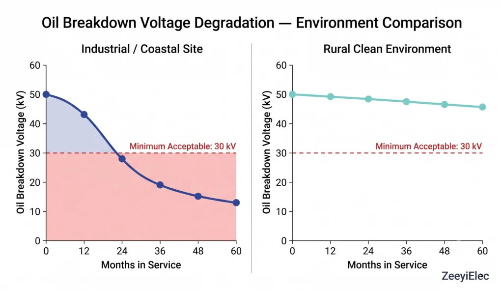
Oil Degradation Timelines: What Field Data Actually Shows
Field maintenance data from a Southeast Asian utility operating approximately 200 oil-type switching devices across 11 kV and 24 kV networks showed that units in urban industrial corridors exposed to sulfur dioxide (SO2) and particulate contamination through imperfect tank seals reached the 30 kV breakdown threshold within 18–24 months of installation, against an originally planned 5-year interval. Units on rural feeders maintained breakdown values above 45 kV at the 5-year inspection point. A risk-stratified approach 18-month intervals for industrial and coastal sites, 4–5 year intervals for clean rural environments reduces both over-testing cost and under-testing risk simultaneously.
Oil dielectric breakdown voltage degradation profiles for oil immersed loadbreak switches in two installation environments: industrial/coastal sites reach the 30 kV replacement threshold within 18–24 months, while clean rural sites maintain acceptable breakdown values beyond 60 months
Interchangeability Challenges When Replacing Across Brands
Brand switching during a replacement cycle introduces dimensional and interface compatibility risks underestimated at procurement stage. Tank cover flange bolt patterns, operating shaft height, and bushing centerline spacing vary between manufacturers even within the same nominal rating. A 24 kV, 630 A switch from one manufacturer may have a shaft centerline height of 185 mm above the tank cover, while a nominally equivalent unit from another sits at 210 mm, a 25 mm discrepancy preventing direct installation into an existing pole-mount bracket without modification. Electrical interchangeability carries additional risk: if the replacement unit’s bushing creepage distance differs from the original, the as-installed insulation coordination of the transformer-switch assembly changes from its type-tested configuration. Field engineers managing aging fleets recommend maintaining dimensional drawings from the original installation package and issuing dimensional compatibility requirements not just electrical ratings as mandatory RFQ parameters for replacement units.
How ZeeyiElec Loadbreak Switches Fit Medium Voltage Distribution Projects
ZeeyiElec manufactures oil immersed loadbreak switches covering 11 kV to 36 kV at rated currents of 200 A, 400 A, and 630 A, the standard configuration band covering the majority of distribution transformer switching applications on utility, EPC, and industrial network projects.
Product Positioning Within the Competitive Landscape
Within the Tier 2 export manufacturer segment, ZeeyiElec’s principal differentiator is ecosystem compatibility. Loadbreak switches are specified and supplied alongside the broader transformer accessories range including medium-voltage bushings, Bay-O-Net fuse assemblies, current limiting fuses, and off-circuit tap changers which means dimensional and electrical interface compatibility across the transformer accessory package is verifiable from a single supplier’s documentation set rather than requiring cross-manufacturer reconciliation.
Export Documentation and Compliance Support
ZeeyiElec supplies routine test certificates per unit, IEC-referenced technical datasheets, and export documentation packages structured for Letter of Credit compliance and customs clearance across primary export markets in Africa, the Middle East, and Southeast Asia. For projects requiring country-specific certification, the technical team can advise on applicable compliance pathways before order confirmation.
Request a Technical Datasheet or Project Quotation
Specify your voltage class, rated current, installation environment (indoor / outdoor / tropical / high altitude), and required short-circuit withstand level and the ZeeyiElec technical team will return a datasheet match and quotation response.
Maintenance, Oil Management, and End-of-Life Considerations
A switch purchased to a sound specification and installed correctly will underperform its rated service life if oil condition deteriorates undetected. Oil is not a passive fill medium, it is an active insulating and arc-quenching component whose dielectric properties degrade continuously under moisture ingress, oxidation, switching arc byproducts, and thermal cycling.
Routine Oil Sampling and Dielectric Strength Testing
The foundational maintenance measurement is dielectric breakdown voltage, tested using a standard 2.5 mm electrode gap. Acceptable in-service oil should maintain a breakdown voltage of ≥ 30 kV; oil testing below this threshold warrants immediate filtering or replacement before the next switching operation. New replacement oil should test at ≥ 50 kV prior to filling. Beyond breakdown voltage, dissolved gas analysis (DGA) on oil samples can detect early-stage internal arcing elevated acetylene (C2H2) concentration above approximately 5 ppm is a recognized indicator of abnormal arcing activity warranting investigation before continued service.
Testing frequency should follow a risk-stratified schedule: 18–24 months for industrial corridor, coastal, and high-humidity sites; 4–5 years for clean rural installations with low switching frequency and intact tank seals.
Contact Wear Inspection and Mechanical Operation Count
Oil immersed loadbreak switch contacts erode incrementally with each load-current interruption. Cumulative erosion becomes significant after 150 to 300 load-current operations depending on current magnitude and contact material. Maintenance inspection should include visual examination of contact faces for pitting depth whenever the tank is opened for oil servicing. Manufacturers typically specify a maximum allowable contact erosion depth in the range of 1.5 mm to 3.0 mm, beyond which contact replacement is mandatory to maintain reliable arc interruption. Tracking cumulative operation counts in a maintenance log, rather than relying solely on calendar-based triggers provides a more accurate indicator of actual contact wear state.
Mechanical endurance checks should verify operating mechanism spring tension, shaft seal integrity, and handle or motor operator torque. A shaft seal showing oil weeping at the tank cover penetration point requires immediate attention: progressive oil loss reduces the arc-quenching oil column length inside the tank, degrading interruption performance at rated current before any electrical symptom appears.
Oil Disposal and Environmental Compliance at End of Service Life
Used dielectric oil contains arc decomposition byproducts, carbon particles and low-molecular-weight hydrocarbons that preclude disposal as general industrial waste in most jurisdictions. Responsible end-of-life practice involves engaging a licensed oil reclamation contractor, retaining disposal certificates for regulatory documentation, and where reclamation is available, sending serviceable oil for re-refining rather than incineration. On projects where multiple transformer accessories are decommissioned simultaneously, consolidating oil volumes across bushings, tap changers, and loadbreak switches into a single waste oil collection event reduces mobilization cost per liter disposed.
Frequently Asked Questions
What is the difference between an oil immersed loadbreak switch and a vacuum loadbreak switch?
Oil immersed types use dielectric oil for arc quenching and insulation, making them cost-effective for 11–36 kV radial and ring-main applications in price-sensitive markets; vacuum types eliminate oil maintenance entirely but carry higher first cost, typically preferred where maintenance access is limited or fire risk is a concern.
What current ratings are available for oil immersed loadbreak switches in medium voltage networks?
Standard rated currents span 200 A, 400 A, and 630 A across voltage classes of 11 kV, 15 kV, 24 kV, and 36 kV; the appropriate rating depends on feeder load current, prospective short-circuit level, and the capacity margin required over the asset’s planned service life.
How often should the oil in a loadbreak switch be tested or replaced?
Field practice involves dielectric strength testing every 18–24 months for industrial and coastal environments and every 4–5 years for clean rural sites; oil breakdown voltage below 30 kV across a 2.5 mm gap is the standard replacement trigger regardless of elapsed time since last service.
Which IEC standard governs the testing and performance of oil immersed loadbreak switches?
IEC 62271-103 addresses AC switches for rated voltages above 1 kV up to 52 kV and is the primary reference for type testing, rated characteristics, and operational endurance; regional utility projects may additionally require compliance with local specifications that modify or extend the IEC baseline requirements.
Can an oil immersed loadbreak switch replace an off-circuit tap changer on a distribution transformer?
No — a loadbreak switch interrupts load current with the transformer energized, while an off-circuit tap changer adjusts voltage ratio only after complete de-energization; they perform fundamentally different functions and are not interchangeable, as detailed in the ZeeyiElec comparison guide.
What altitude derating applies to oil immersed loadbreak switches installed above 1,000 m?
Above 1,000 m, reduced air density lowers external insulation performance, typically requiring voltage class uprating or explicit high-altitude type testing; derating applies from 1,000 m to 4,000 m with correction coefficients varying by design and specified in manufacturer technical documentation.
How do I verify that a replacement loadbreak switch is compatible with my existing transformer accessory configuration?
Compatibility verification covers flange bolt circle diameter, operating shaft height above the tank cover, bushing centerline spacing, and bushing voltage class alignment; requesting certified dimensional drawings and confirming against the original transformer accessory pocket specification before purchase order is standard practice on retrofit and fleet replacement projects.
yoyo shi
Yoyo Shi writes for ZeeyiElec, focusing on medium-voltage accessories, transformer components, and cable accessory solutions. Her articles cover product applications, technical basics, and sourcing insights for global electrical industry buyers.