LV bushing thermal stability depends on choosing the right material — HTN, porous resin, or porcelain — for a given current rating and enclosure environment. Getting that choice wrong shows up first as a hot terminal, then as accelerated insulation aging.
Selecting between HTN, porous resin, and porcelain for a low voltage transformer bushing comes down to one core question: how well does the material manage heat at the conductor interface without losing dielectric strength or mechanical integrity over years of service? Current rating, thermal class, and enclosure conditions all factor into that decision, and getting it wrong shows up first as a hot terminal, then as accelerated insulation aging.
What Determines Thermal Stability in LV Bushing Materials
Thermal stability depends on how effectively a material conducts heat away from the conductor interface while resisting the mechanical stress that comes from repeated temperature swings. As current passes through the internal conductor stem, resistive heating raises local temperature, and the surrounding insulation has to move that heat outward without softening, cracking, or degrading its dielectric properties.
Thermal Class and Continuous Operating Temperature
LV bushing insulation is rated by thermal class, which sets the maximum continuous operating temperature the material can sustain without accelerated aging. Typical LV bushing insulation falls in the 105°C to 155°C thermal class range, with current ratings spanning 600A to 5000A+ depending on conductor cross-section and terminal configuration. A bushing running near the top of its current rating inside a poorly ventilated cabinet operates closer to its thermal class ceiling, which narrows the margin before insulation aging speeds up.
Heat Dissipation Path
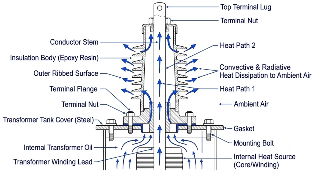
Heat generated at the conductor stem has to travel through the insulation body and terminal flange before it reaches ambient air. Materials with lower thermal conductivity create a steeper internal temperature gradient, meaning the hottest point inside the bushing can run noticeably higher than what a surface thermal camera reading would suggest. This is why surface temperature checks alone can understate internal thermal stress, particularly on fully enclosed porcelain designs compared to more open resin structures.
Thermal Cycling and Expansion Stress
Daily load variation plus seasonal ambient swings create differential expansion between the conductor stem, insulation body, and metal flange. Over years of service, that cycling can loosen terminal connections or introduce micro-cracking where dissimilar materials meet without enough mechanical tolerance — a long-term mechanical fatigue mechanism that routine dielectric-focused bushing standards don’t directly test for, though it shows up consistently in field service records.
Internal heat dissipation path through an LV bushing, from conductor stem through insulation body to ambient air, with thermal gradient callouts.For how this bushing category fits into transformer accessory selection overall, see ZeeyiElec’s transformer accessories overview.
Material Options Compared: HTN, Porous Resin, and Porcelain
Three material families dominate LV bushing construction, and each has a distinct thermal-mechanical profile.
HTN (High Temperature Nylon)
HTN bushings use a glass-reinforced nylon body, typically rated in the 130°C to 155°C thermal class range depending on formulation and glass-fill percentage. The material’s relatively low mass and moderate thermal conductivity allow reasonably fast heat dissipation in open-air enclosures, and its flexibility under mechanical load makes it less prone to cracking during thermal cycling than rigid ceramic bodies. HTN suits compact pad-mount enclosures where current ratings commonly run 600A to 2000A.
Porous Resin
Porous resin sits in a similar thermal class band but relies on a cast structure with different internal void characteristics that affect heat transfer. Resin bodies generally tolerate moderate overload for limited durations, though sustained operation near the top of the current rating accelerates resin aging more noticeably than in HTN designs. Field replacement records on older resin bushings often show surface crazing near terminal connection points — typically an early indicator of accumulated thermal cycling stress rather than a single overload event.
Porcelain
Porcelain offers strong dimensional stability under sustained heat and holds up well to UV exposure and long-term outdoor weathering, making it a common choice where current ratings extend toward the 3000A to 5000A+ range on higher-capacity distribution transformers. Its brittleness, though, means thermal shock — a rapid temperature change rather than gradual cycling — poses a greater cracking risk than for HTN or resin. Porcelain also has lower impact resistance during installation, a practical field consideration separate from thermal performance.
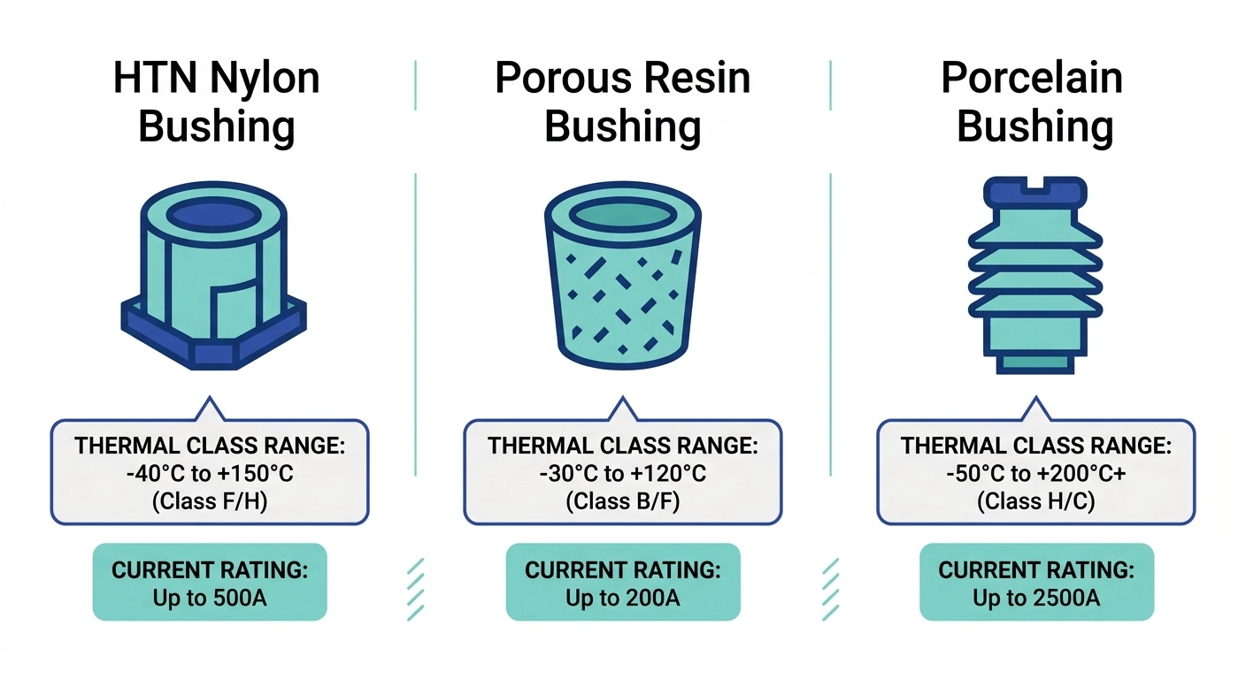
Approximate thermal class comparison: HTN ≈ 130°C–155°C, Porous Resin ≈ 130°C–155°C, Porcelain ≈ 155°C+ (material-dependent, subject to manufacturer certification).
[Expert Insight]
No single material wins on thermal stability alone — application context decides it
HTN’s flexibility helps most where load cycling is frequent, not just where current is high
Resin crazing near terminals is a maintenance flag, not an automatic failure
Porcelain’s biggest field risk is installation handling, not steady-state heat
For the full technical breakdown of bushing sizing, see ZeeyiElec’s low voltage bushings series page, and for how LV bushings compare structurally to medium-voltage designs, see the LV vs MV bushing selection guide.
Thermal Stability Selection Matrix by Current Rating and Application
Matching bushing material to application is the core of LV bushing thermal stability — weighing current rating, enclosure ventilation, and expected thermal cycling frequency together, not evaluating any one parameter in isolation.
Selection Matrix by Material, Thermal Class, and Application
A transformer feeding a facility with sharp daily load swings — say, cycling between 40% and 90% of rated load within a few hours — puts more thermal cycling stress on the bushing than a utility feeder holding a flat load profile at the same average current. In that scenario, HTN’s flexibility under cycling can be a practical advantage even where porcelain would otherwise fit the current rating.
Enclosure ventilation is the second major factor. A bushing rated for 2000A in an open-air outdoor installation may run cooler than the same rating inside a sealed pad-mount cabinet with limited airflow, so nameplate current rating alone doesn’t tell the full thermal story — ambient enclosure conditions need to be factored in.
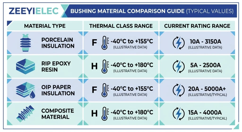
Selection matrix mapping HTN, porous resin, and porcelain bushing materials against thermal class, current rating, and best-fit application scenarios.Procurement teams cross-referencing this against a full transformer accessory RFQ can use ZeeyiElec’s transformer accessories RFQ checklist for the complete parameter list needed at quotation stage.
Field Conditions That Stress Thermal Performance
Lab thermal class ratings describe material behavior under controlled conditions, but field installations rarely match test-chamber uniformity. Ambient temperature, enclosure design, and loading pattern all interact to push actual operating temperatures above or below what the nameplate rating alone would suggest.
High-Ambient / Poor Ventilation Environments
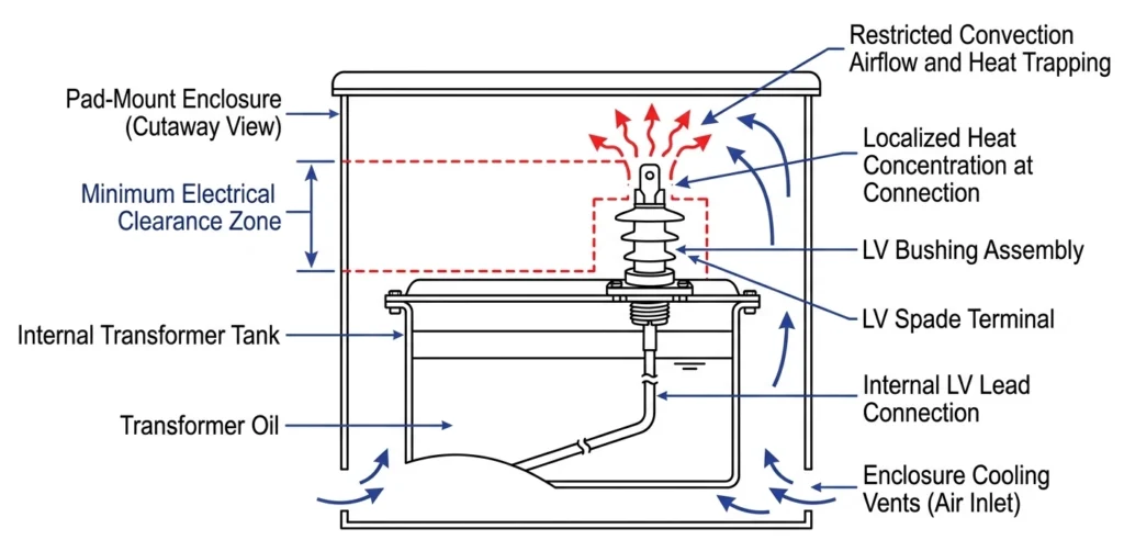
Enclosures with restricted airflow — common in compact pad-mount cabinets or indoor switchgear rooms — trap heat around the bushing terminal, raising effective operating temperature above open-air conditions at the same current. In field surveys of transformers operating in enclosures with ambient temperatures reaching 40°C to 45°C during peak summer conditions, bushing surface temperatures have measured 15°C to 20°C above open-air installations carrying identical load. That gap matters most for materials already running near the top of their thermal class, where a modest additional temperature rise can meaningfully shorten expected insulation life.
Cyclic Overload Conditions
Distribution transformers serving mixed commercial or industrial loads often see current cycling between 50% and 110% of rated capacity within a single day rather than holding a steady average load. This repeated expansion-contraction cycling stresses the conductor-to-insulation interface more than sustained loading at a lower average current would. On commissioning work for transformers feeding facilities with heavy motor-starting loads, bushings subjected to frequent inrush-driven thermal cycling have shown earlier terminal connection loosening at scheduled maintenance checks compared to bushings on steadier commercial loads carrying similar average current.
LV bushing installed in a pad-mount enclosure, illustrating ventilation clearance zones and ambient heat buildup areas around the terminal.
Installation and Commissioning Checks for Thermal Reliability
Installation practice has a direct bearing on long-term thermal performance — loose terminal connections, inadequate torque, or restricted clearance at commissioning are often the earliest sources of localized heating.
Pre-Energization Checks
Terminal connections should be torqued to the manufacturer’s specified value — commonly 15 N·m to 40 N·m for LV bushing terminal hardware depending on stud size and current rating — since under-torqued connections raise contact resistance and create a localized hot spot under load. Installers should also confirm clearance around the bushing body matches the enclosure manufacturer’s ventilation allowance, typically 50mm to 100mm depending on cabinet design, to avoid trapping heat against adjacent components. Undersized clearance in densely packed pad-mount cabinets has been a recurring root cause when thermal imaging later flags an unexpectedly hot bushing during initial energization testing.
Post-Energization Thermal Scan
A thermal imaging scan performed within the first 24 to 72 hours of energization, ideally near expected peak load, establishes a baseline temperature profile for each bushing and terminal connection. A reading roughly 10°C or more above comparable bushings carrying similar current is generally worth investigating with a torque recheck before it’s attributed to a material or design issue. This baseline also gives maintenance teams a reference point for spotting thermal drift at future inspections.
Skipping the post-energization thermal scan removes the clearest signal for catching an installation defect early
A 10°C+ gap between comparable bushings is the practical threshold for a torque recheck
Clearance shortfalls in tight cabinets are a more common root cause than material defects
Common Thermal Failure Modes and Diagnostic Indicators
Thermal-related bushing failures usually develop gradually, and catching early diagnostic indicators during routine maintenance can prevent an unplanned outage caused by a fully degraded terminal connection or cracked insulation body.
Discoloration and Surface Crazing
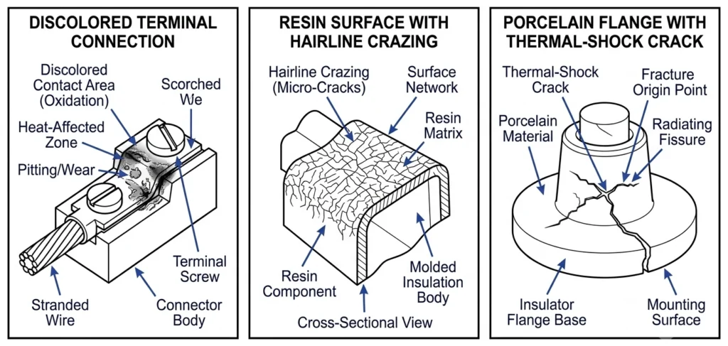
Progressive discoloration at the terminal connection point — light tan to dark brown staining on resin or HTN surfaces — usually points to sustained overheating at that specific contact rather than uniform aging across the whole bushing. Fine surface crazing, a network of shallow hairline cracks, often appears on resin bodies after repeated thermal cycling and is generally an early-stage indicator rather than an immediate failure risk, though it should be logged and monitored.
Terminal Loosening and Rising Contact Resistance
Repeated thermal expansion and contraction at the conductor-to-terminal interface can gradually loosen mechanical connections, raising contact resistance and creating a self-reinforcing heating cycle. A measured contact resistance increase of roughly 20% or more above the commissioning baseline is a reasonable trigger point for scheduling a torque recheck at the next planned outage.
Insulation Cracking (Porcelain-Specific)
Because porcelain is brittle relative to HTN or resin, its dominant failure mode is cracking from thermal shock — a sudden cold-water contact during a storm following sustained high-load heating, for example — rather than the gradual crazing seen in polymer materials. Visual inspection for hairline cracks near the flange-to-shed transition is a standard part of periodic porcelain bushing maintenance.
Side-by-side comparison of common LV bushing thermal failure modes: terminal discoloration, resin surface crazing, and porcelain insulation cracking.
Thermal aging behavior for transformer insulation systems generally follows the temperature-life relationship established by IEEE C57.91, which models winding insulation aging using Montsinger’s rule and the Arrhenius relationship — the same underlying thermal-endurance principle that governs bushing insulation materials, though C57.91 itself is scoped to oil-immersed transformer insulation systems rather than bushing-specific materials.
Get Engineering Support for LV Bushing Material Selection
Selecting the right LV bushing material for a given thermal profile depends on details specific to each installation — enclosure type, ambient conditions, current rating, and expected load cycling pattern. Sharing transformer nameplate data and enclosure specifications allows for a more precise recommendation than general guidelines alone can provide.
ZeeyiElec’s technical team supports LV bushing selection across HTN, porous resin, and porcelain options, matching material to current rating (600A–5000A+) and thermal class requirements (105°C–155°C) based on actual project conditions rather than default assumptions, including enclosure ventilation constraints and expected duty cycle.
For projects still finalizing the full accessory scope, ZeeyiElec’s cable accessories line addresses similar thermal and environmental considerations on the cable side of a project.
Submit transformer nameplate details, enclosure drawings, or existing bushing specifications for a technical review and quotation response.
Frequently Asked Questions
What thermal class is typical for LV transformer bushings?
LV bushing materials generally fall in the 105°C–155°C thermal class range depending on resin or nylon formulation, though the exact class depends on the manufacturer’s material certification and mounting configuration.
Is HTN or porcelain better for high-temperature environments?
HTN typically resists thermal cycling and mechanical shock better in compact designs, while porcelain holds dimensional stability well under sustained heat, so the better choice depends on ambient conditions and current loading pattern rather than one material being universally superior.
Can porous resin bushings handle overload conditions?
Porous resin can tolerate moderate overload for limited durations, but repeated cyclic overloading accelerates thermal aging, so duty cycle and cooling design should be checked against the manufacturer’s rating before relying on overload margin.
How does current rating affect material selection for thermal stability?
Higher current ratings generate more resistive heating at the terminal interface, which generally favors materials with a higher thermal class and better heat dissipation, though enclosure ventilation plays an equally significant role in the final decision.
What signs indicate thermal degradation in an LV bushing?
Common indicators include surface discoloration, minor surface crazing, or terminal loosening from repeated thermal expansion, and any of these findings typically warrant closer inspection during scheduled maintenance rather than immediate replacement.
Does ambient temperature change which bushing material is recommended?
Yes — installations in consistently high-ambient or poorly ventilated enclosures often benefit from a material with a higher continuous thermal rating, while standard ambient conditions allow more material flexibility.
How often should thermal scans be repeated after commissioning?
Many operators repeat thermal imaging at annual maintenance intervals or after any significant load profile change, since a shift from the commissioning baseline is often the first measurable sign of developing thermal stress.
yoyo shi
Yoyo Shi writes for ZeeyiElec, focusing on medium-voltage accessories, transformer components, and cable accessory solutions. Her articles cover product applications, technical basics, and sourcing insights for global electrical industry buyers.





 English
 한국어
한국어 العربية
 Español
 हिन्दी
 தமிழ்
தமிழ் Deutsch (Sie)
 Français
 Português do Brasil
 Русский