연락처 정보
지이일렉은 글로벌 유통업체와 프로젝트 계약업체를 위한 변압기 및 케이블 액세서리를 공급합니다. 기술 선택 및 RFQ 지원은 당사에 문의하세요.
주소:
리우시, 웨칭, 원저우, 저장성, 중국
전화 / WhatsApp / 위챗:
+86 150 5877 8024
이메일:
[email protected]
안정적인 품질, 실용적인 리드 타임, 수출 지원으로 공장에서 직접 부품을 조달하세요.
아래 양식을 작성하여 카탈로그와 가격을 받아보세요.
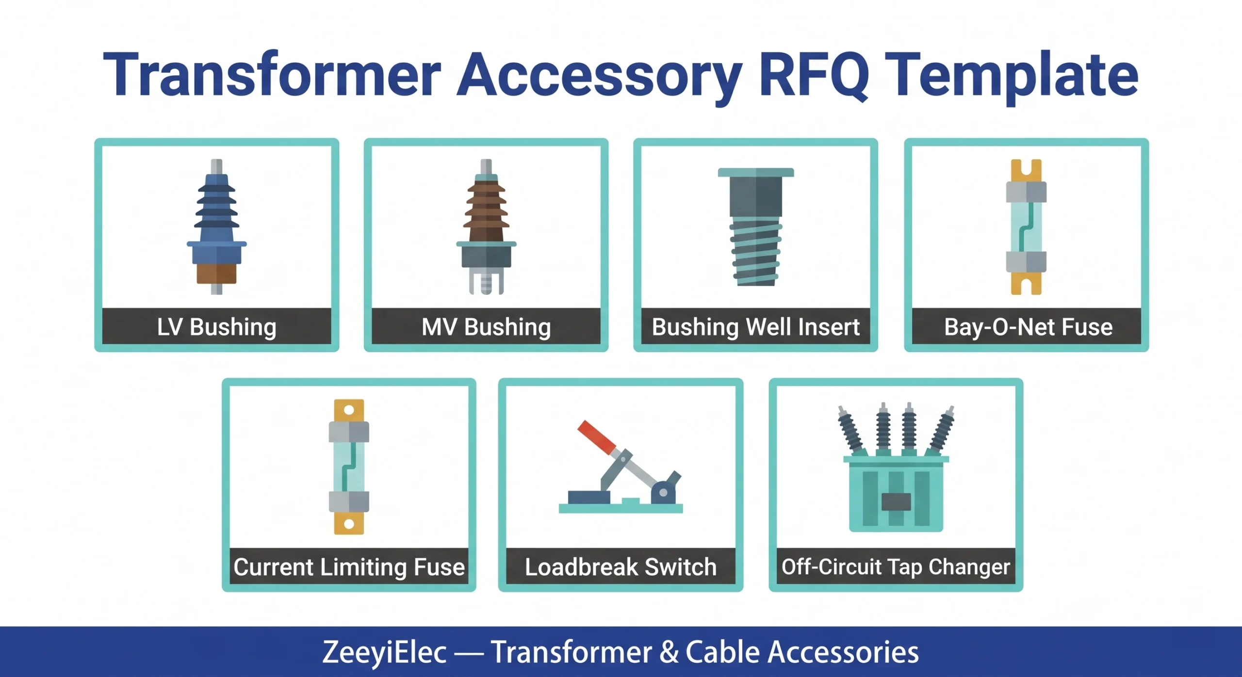
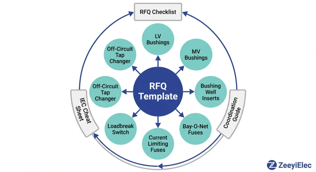
A complete transformer accessory RFQ requires: transformer nameplate data (kVA, HV/LV voltage, vector group, cooling type), highest system voltage Um in kV, BIL in kVp, site conditions (altitude, pollution class, ambient temperature), quantity with spare ratios per family, and accessory-specific parameter fields for all seven families LV/MV bushings, bushing well inserts, Bay-O-Net fuses, current limiting fuses, loadbreak switches, and off-circuit tap changers.
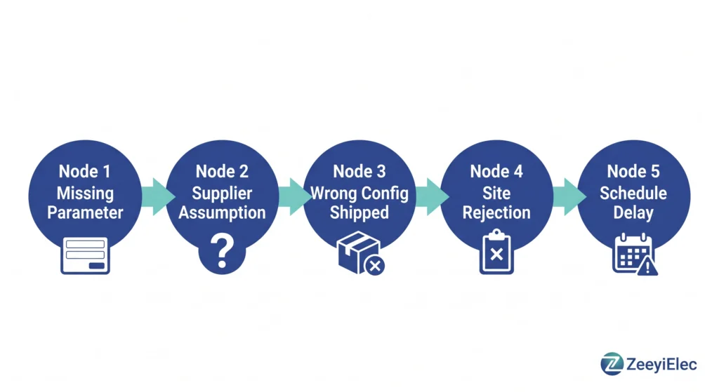
Procurement teams routinely underestimate how much specification detail a transformer accessory order requires. A nameplate provides kVA rating and voltage ratio it does not specify bushing BIL, fuse coordination thresholds, tap changer current rating, or contamination class. When those parameters are missing, the supplier guesses, requests clarification, or ships the nearest available configuration. Field data consistently points to incomplete RFQs as the primary driver of accessory mismatches not counterfeit product, not manufacturing defect.
Two procurement failure scenarios illustrate the cost:
A project specified “35 kV class bushings” without confirming BIL. The supplier shipped 170 kVp units; the insulation coordination study required 200 kVp. Replacement units required re-manufacturing. Commissioning shifted by 23 days.
A Bay-O-Net fuse link was selected at 65 A against a transformer with an 83 A full-load primary current at 15 kV. The coordination margin was negative before the transformer was energized. Both fuse accessories required replacement.
The sections below structure specification into required, conditional, and optional fields across all seven transformer accessory families available through ZeeyiElec’s transformer accessories range.
This template addresses seven transformer accessory families in the 10–35 kV range. Before completing any section, confirm transformer nameplate data is available attempting to size fuse links or tap changer steps without a confirmed nameplate introduces specification errors that propagate through every downstream field.
Each section uses REQUIRED, CONDITIONAL, and OPTIONAL field designations. REQUIRED fields must be completed before submission; CONDITIONAL fields apply only when a specific configuration is selected; OPTIONAL fields improve quotation accuracy but will not block a valid supplier response. On-load tap changers, protection relays, transformer oil, and cable accessories fall outside this template’s scope.
Every RFQ requires a completed header block before any accessory-specific fields are addressed. Suppliers use it to confirm compatibility across the full accessory scope and flag configuration conflicts before manufacturing begins.
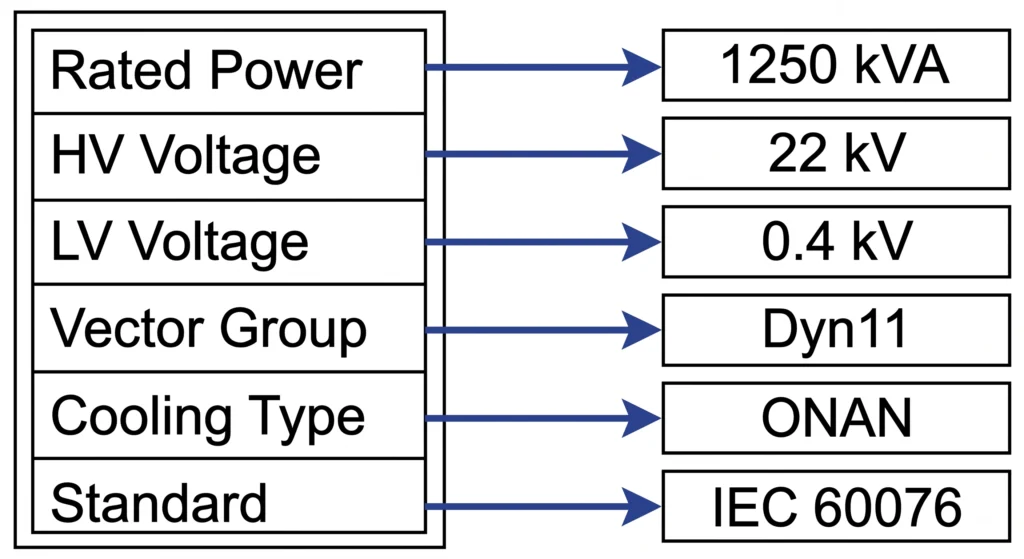
| Field | Example Entry | 참고 |
|---|---|---|
| Rated power | 1,250 kVA | Confirm MVA for large units |
| HV voltage | 22 kV | Nominal — not highest system voltage |
| LV voltage | 0.4 kV | Secondary winding output |
| Vector group | Dyn11 | Affects bushing phase arrangement |
| Cooling type | ONAN | ONAN / ONAF / OFAF |
| Applicable standard | IEC 60076 | Or ANSI/IEEE C57 series |
Highest system voltage Um must be stated separately from nominal voltage. For a 22 kV nominal system, Um typically reaches 24 kV this value directly governs bushing creepage distance and BIL selection.
Basic insulation level (BIL) must be stated in kVp. For 24 kV Um class, standard BIL values are 125 kVp or 145 kVp depending on the insulation coordination study. Confirm which applies before completing bushing and fuse sections. [VERIFY STANDARD: IEC 60071-1 insulation coordination confirm BIL table for Um = 24 kV]
Additional required site fields: installation altitude in metres dielectric derating applies above 1,000 m; maximum ambient temperature (°C) typical range 40°C to 50°C for tropical and desert sites; pollution level per IEC classes I–IV; and installation environment (indoor / outdoor / pad-mounted / pole-mounted).
Altitude and contamination class are the two site parameters most frequently omitted from first-draft transformer accessory RFQs. Both directly determine whether a standard-catalogue bushing is acceptable or whether an upgraded creepage configuration is required.
Specify spare ratios per accessory family: 10–15% for consumable fuse links; 5% or one spare unit per project for non-consumables such as bushings and tap changers. Confirm export documentation requirements at header stage test reports, certificate of origin, packing list, and HS code classification are standard minimums. The IEC specification and procurement cheat sheet provides a parallel reference for standards alignment across these header fields.
[전문가 인사이트]
- Um and nominal voltage diverge by 5–15% depending on system design always use Um for bushing and fuse specification, never nominal voltage alone
- Pollution class IV (very heavy) requires creepage distances of 53 mm/kV or greater catalogue bushings rated for class II (25 mm/kV) will track and fail within one wet season at coastal industrial sites
Bushings require simultaneous confirmation of electrical class, mechanical interface, insulation material, and terminal configuration. A bushing that is electrically correct but dimensionally incompatible with the tank flange cannot be installed. One that fits mechanically but carries insufficient creepage for the site pollution class will fail within its first wet season.
| Field | Range / Options | 참고 |
|---|---|---|
| 전압 등급 | 1.2 kV / 2.0 kV / 3.0 kV | Match to transformer LV winding |
| 현재 등급 | 600 A – 5,000 A+ | Calculate from kVA ÷ (√3 × LV kV) |
| Insulation material | HTN / porous resin / porcelain / epoxy | HTN preferred for high-humidity sites |
| Terminal configuration | Flat pad / threaded stud / DIN spade | Confirm cable lug or busbar interface |
| Mounting flange OD | State in mm | Must match transformer tank bore |
For a 1,000 kVA transformer with LV winding at 0.4 kV, secondary current reaches approximately 1,443 A per phase (I = S ÷ (√3 × ULV)). A bushing rated at 1,250 A continuous would be undersized specify 1,600 A minimum with a 10% thermal margin confirmed by the supplier.
The applicable standard for bushing performance testing is IEC 60137, which defines impulse withstand, power frequency withstand, and thermal current rating test requirements for bushings in liquid-filled transformers.
| Field | Range / Options | 참고 |
|---|---|---|
| 전압 등급(Um) | 12 kV / 24 kV / 36 kV / 52 kV | State Um, not nominal |
| 현재 등급 | 55 A – 3,150 A | Per phase; calculate from HV side |
| BIL | 75 kVp – 250 kVp | Match insulation coordination study |
| Standard interface | ANSI porcelain / DIN porcelain / epoxy | Confirm transformer OEM preference |
| 연면 거리 | 25 mm/kV (light) – 53 mm/kV (very heavy) | Per IEC 60815 pollution class |
For projects bridging ANSI and IEC supply chains common in Middle East and Southeast Asian utility tenders confirm interface standard explicitly. ANSI and DIN porcelain MV bushings are not interchangeable at the transformer flange; field substitution is not feasible without adapter hardware.
| Field | Range / Options | 참고 |
|---|---|---|
| 전압 등급 | 15/25 kV or 15/25/35 kV | Two standard class groups |
| 현재 등급 | 200 A continuous | Fixed by deadfront system geometry |
| Elbow acceptance | Confirm Y/N | State loadbreak or non-loadbreak elbow |
Confirm elbow manufacturer compatibility at RFQ stage. Dimensional differences at the elbow interface that prevent full seating are only detectable during energization preparation — not during visual inspection after delivery.
Fuse coordination must be resolved before either fuse family is sized. Switch voltage class must be confirmed against Um, not nominal voltage. These three families are interdependent — an incomplete specification in any one affects the validity of the other two.
| Field | Range / Options | 참고 |
|---|---|---|
| 전압 등급 | 15 kV / 25 kV | Match to HV winding Um |
| BIL | 150 kVp | Standard for 15/25 kV class |
| Fuse link current rating | 6 A – 200 A | Size from FLA + inrush margin |
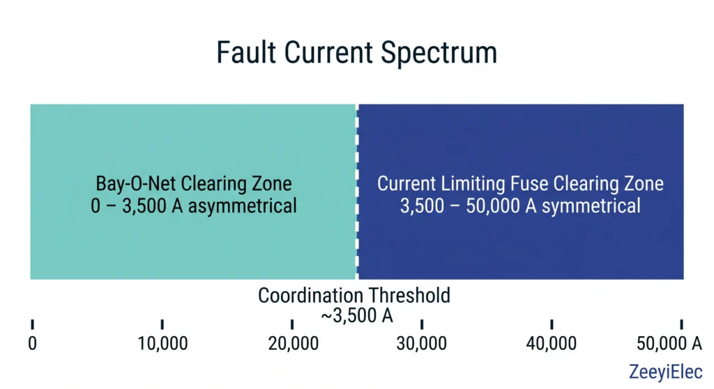
| Interrupting rating | Up to ~3,500 A asymmetrical | Expulsion limit; CLF handles above |
| Hot-stick operability | Required Y/N | Mandatory for live-front installations |
In pad-mounted installations with restricted enclosure clearances, confirm the expulsion arc path is unobstructed before specifying an open-expulsion Bay-O-Net assembly.
Per IEC 60282-1, current limiting fuses for transformer protection must be characterized by rated voltage, continuous current, and maximum interrupting current all three are required RFQ fields without exception.
| Field | Range / Options | 참고 |
|---|---|---|
| System voltage | 12 kV / 24 kV / 36 kV | State Um |
| Rated continuous current | 2 A – 200 A | Size from transformer HV FLA |
| Maximum interrupting current | Up to 50 kA symmetrical | Confirm against fault level study |
| Coordination threshold | ~2,500 A – 3,500 A | Confirm handoff with protection engineer |
| Let-through I²t | State in A²s | Required for winding damage assessment |
The let-through energy of a current limiting fuse is expressed as I2t in units of A2s. For transformer protection coordination, the fuse I2t at maximum fault current must remain below the transformer’s withstand I2t derived from short-circuit impedance Zk % and winding thermal time constant. Omitting this field prevents the supplier from confirming the protection margin.
그리고 Bay-O-Net vs current limiting fuse coordination guide provides the technical basis for completing both fuse sections in a coordinated submission.
| Field | Range / Options | 참고 |
|---|---|---|
| 전압 등급 | 15/25 kV or 38/40.5 kV | Match to HV system Um |
| 현재 등급 | 630 A continuous | Standard for distribution class |
| 구성 | 2-position / 4-position | 4-position for loop-feed applications |
| 작동 모드 | Hook-stick / stored-energy | Stored-energy preferred |
| Motor operator | Y/N | Required for SCADA-integrated switching |
Stored-energy mechanisms are preferred over direct manual operation at 15 kV and above interruption speed is consistent regardless of operator technique, directly reducing contact erosion rate across the switch’s service life.
[전문가 인사이트]
- Never size a Bay-O-Net fuse link from transformer kVA alone full-load primary current must be calculated, then multiplied by an inrush margin of 8–12× FLA for 0.1 s to avoid nuisance operation during energization
- Let-through I²t must be confirmed against the transformer’s short-circuit withstand rating before fuse selection procurement teams frequently omit this field, treating it as a supplier responsibility when it is not
Off-circuit tap changers adjust transformer turns ratio across a discrete set of positions typically five, spaced at 2.5% intervals giving ±5% adjustment around the nominal voltage ratio. The transformer must be fully de-energized before any position change; this constraint governs every parameter in this section.
| Field | Range / Options | 참고 |
|---|---|---|
| 전압 등급 | 15 kV / 25 kV / 35 kV | Match to HV winding Um |
| 현재 등급 | 63 A / 125 A | Select from transformer HV FLA |
| 포지션 수 | 5 (standard) | ±2 × 2.5% around nominal |
| Tap step voltage | Calculate in V | HV winding voltage × 2.5% per step |
| Rotation type | Linear / rotary | Confirm from transformer OEM drawing |
| Motor operator | Y/N | Conditional — see below |
Tap step voltage must be calculated before RFQ submission. For a transformer with HV winding rated at 22 kV and a standard 5-position tap arrangement, each 2.5% step equals 550 V. The full adjustment range spans 20,900 V (position –2) to 23,100 V (position +2) a total window of 2,200 VAC. Specifying only “22 kV, 5-position” without step voltage confirms nothing about winding compatibility.
Confirming rotation type requires the transformer OEM drawing or direct manufacturer confirmation, it cannot be inferred from kVA rating or voltage class alone. In one documented field case, a replacement tap changer ordered on electrical parameters alone required 40% more linear travel clearance than the tank interior allowed; installation was not possible without internal transformer modification.
| Field | Specify If Applicable |
|---|---|
| Motor operator voltage | 24 V DC / 110 V AC / 230 V AC |
| Control signal type | Local / remote / SCADA interface |
| Position feedback | 4–20 mA / digital pulse / none |
| Environmental enclosure | IP rating for motor housing |
Every tap changer RFQ should request the supplier’s recommended interlock labeling specification. Field incidents involving tap changers operated under load consistently trace to inadequate lockout/tagout labeling or personnel confusion between this device and a loadbreak switch.
| Field | 요구 사항 |
|---|---|
| Quality system | ISO 9001 request current certificate |
| Product certification | CE / RoHS as applicable by destination market |
| Factory test reports | Routine reports required; type test on request |
| Sample lead time | 3–6 weeks typical for standard configurations |
| OEM/ODM capability | Confirm for custom dimensions or private-label marking |
| Export documentation | COO, packing list, test certificate, HS code confirm before PO |
Before submitting, confirm all eight points are resolved:
A single missing item is sufficient grounds for a supplier clarification request resetting the quotation clock by days or weeks.
ZeeyiElec supports technical RFQ responses across all seven transformer accessory families in this template. Submit project parameters and nameplate data via the project inquiry form. For a parallel field-by-field procurement reference with IEC standard alignment notes, the 변압기 액세서리 RFQ 체크리스트 covers the same accessory families. For cable accessory procurement on the same project, the cable accessories series provides a parallel selection and RFQ framework.
At minimum, you need transformer nameplate data (kVA, HV/LV voltage, vector group, cooling type, and applicable standard), highest system voltage Um, BIL in kVp, installation altitude, and site pollution class without these, no accessory family can be correctly specified without supplier assumption filling the gaps.
Calculate the transformer’s full-load primary current using kVA ÷ (√3 × HV kV), then apply an inrush margin of 8 to 12 times FLA for 0.1 seconds to identify a fuse link rating that carries normal load without operating while clearing overload faults below the Bay-O-Net interrupting limit of approximately 2,500–3,500 A.
Nominal voltage is the network’s design reference; Um is the maximum voltage the system sustains under normal operating conditions typically 5–15% higher and bushing creepage distance, BIL, and flashover requirements are all governed by Um, not nominal voltage.
Linear and rotary tap changer mechanisms have different internal travel geometry and tank clearance requirements, meaning a unit specified on electrical parameters alone may need more internal clearance than the transformer allows making installation physically impossible without transformer modification.
Specify a loadbreak switch when the application requires making or breaking load current while the transformer remains energized; specify an off-circuit tap changer when voltage ratio adjustment is needed only during planned de-energization despite similar external appearance, these devices are not operationally interchangeable.
Consumable accessories such as fuse links warrant 10–15% spare allowance per project; non-consumable mechanical components such as bushings, tap changers, and loadbreak switches are commonly held at 5% or one spare unit per project, with higher ratios justified for remote sites where replacement lead times exceed four weeks.
Yes, and consolidating into one submission reduces coordination effort but each accessory family must occupy a separate section with its own parameter fields, since bundling undifferentiated specifications into one block is the most common cause of misquotation and wrong shipment on multi-family transformer accessory orders.
