The Role of Voltage Class in Heat Shrink Termination Design
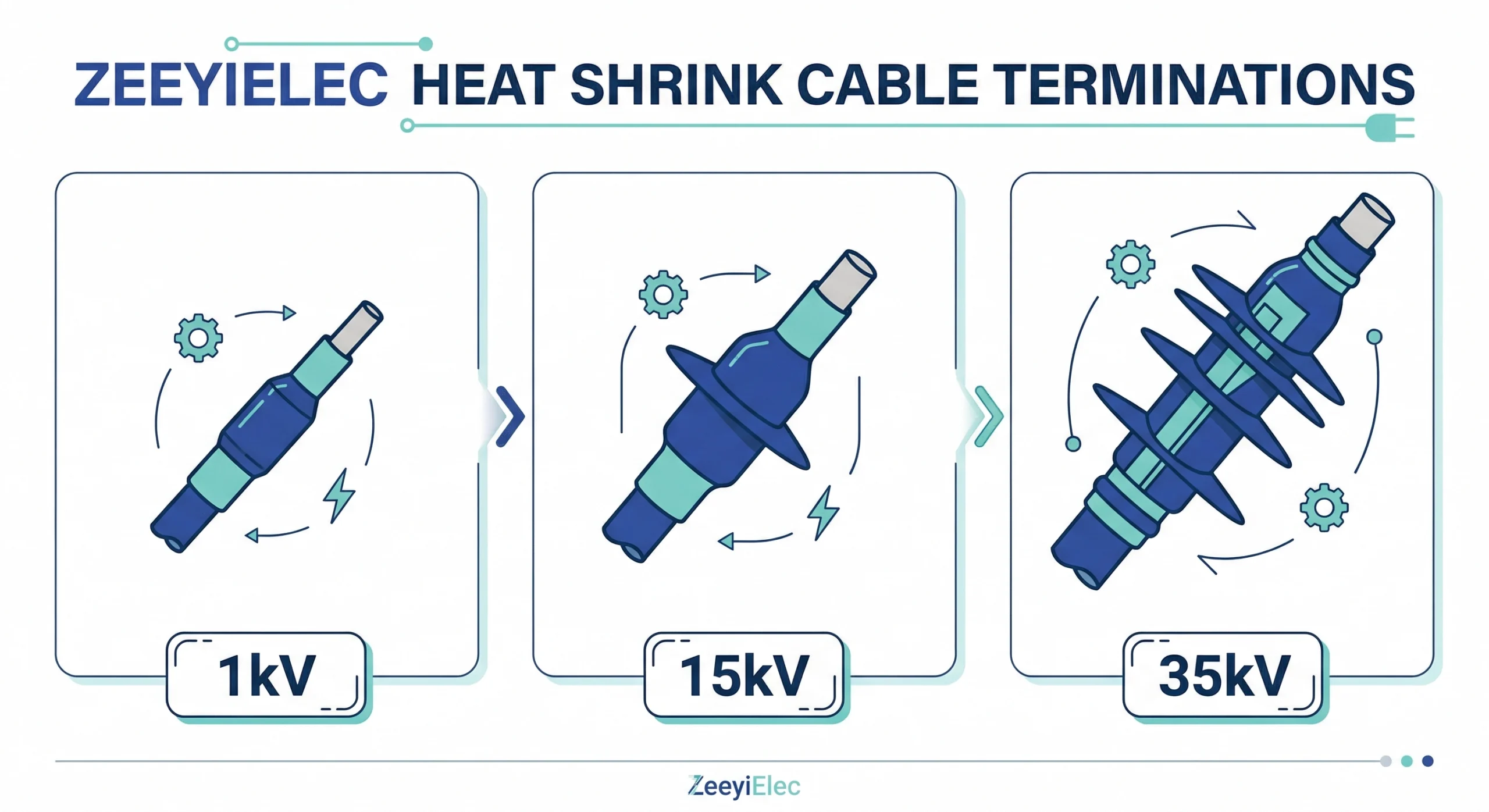
When specifying a heat shrink cable termination, voltage class is the foundational parameter dictating material performance and physical dimensions. A heat shrink termination is not merely a weatherproofing sleeve; it is an engineered dielectric barrier designed to restore insulation integrity and manage the severe electrical stress fields generated at the point where a cable’s factory insulation and screening are removed.
The transition from a continuous cable to an open termination point creates concentrated stress zones, particularly at the semi-conductive screen cut-back. In low voltage (1kV) applications, the electrical stress is relatively benign, meaning the primary function of the heat shrink component is physical protection and environmental sealing against moisture ingress. However, as the system voltage scales to medium voltage classes like 10kV, 20(24)kV, and up to 35kV, the electrical stress field becomes highly concentrated. Without proper management, these levels would cause immediate dielectric breakdown or destructive partial discharge.
To safely operate across these medium voltage gradients, heat shrink terminations employ stress control mechanisms. These typically involve high-permittivity stress control tubes or specially formulated mastics that refract and distribute the electrical field lines evenly along the termination interface, preventing localized stress from exceeding the dielectric strength of the surrounding materials.
The necessary insulation thickness (t) directly correlates with the maximum electric field strength (Emax) and the specific dielectric constant (εr) of the heat shrink material. For example, a 35kV termination requires substantially thicker insulation layers and more complex stress relief geometry than a 10kV termination to ensure the field stress remains well below the critical threshold (typically maintaining operational stress below 3–4 kV/mm in the critical cut-back region).
The dielectric requirements scale predictably with voltage class. A standard 15kV rated termination must successfully pass impulse withstand tests, typically demonstrating a Basic Impulse Level (BIL) of 95kV or 110kV depending on the governing regional standard. This demands a specific combination of material thickness and overlap length during field installation to achieve the necessary creepage distance and prevent flashover.
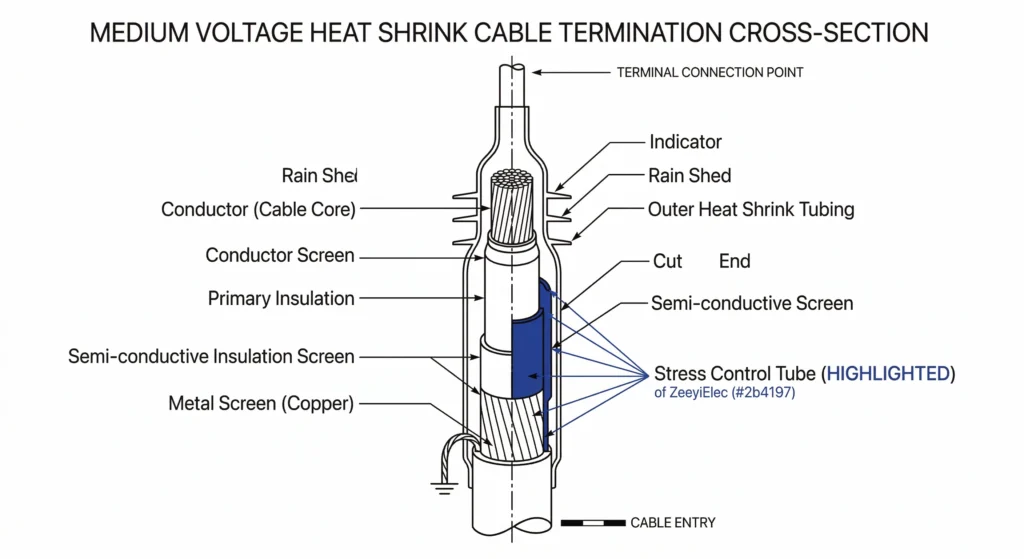
FIG-01:Cross-section illustration of a medium voltage heat shrink termination, highlighting the critical stress control tube positioned over the semi-conductive screen cut-back.
Selection Matrix: 1kV, 10kV, 20(24)kV, and 35kV Applications
Selecting the correct heat shrink termination requires aligning the specific system voltage with the corresponding performance parameters established by international standards. The termination must withstand continuous operating voltage while simultaneously managing transient overvoltages, such as lightning impulses or switching surges. The following sections outline the fundamental requirements across the major voltage tiers.
1kV Heat Shrink Termination Requirements
In 1kV applications, the primary function of the heat shrink component is to provide robust environmental sealing and physical protection for the cable core. Because electrical stress at this level is minimal, these kits generally do not require dedicated stress control tubes. Selection focuses on ensuring proper dimensional fit to the cable cross-section (e.g., 4×185 mm²) and selecting high-quality hot-melt adhesives within the tubing to guarantee a secure, moisture-proof seal over the termination point.
Medium Voltage (10kV to 20kV) Specifications
The transition into the 10kV to 20(24)kV range necessitates active stress management. These kits must incorporate stress control tubing or high-permittivity mastic applied directly over the semi-conductive screen cut-back to refract the electric field. A standard 15kV termination is engineered to meet specific impulse withstand levels (BIL), typically around 95kV. Selection at this tier requires careful matching of the kit to the specific conductor size and insulation diameter to ensure the stress control components are positioned correctly during shrinking. Incorrect sizing here frequently leads to partial discharge and premature failure.
35kV Heat Shrink Termination Kit: Design Demands
Applications operating at 35kV represent the upper echelon of medium voltage distribution and demand the most rigorous heat shrink termination designs. The electrical stress at the screen cut-back in a 35kV system is exceptionally high. Consequently, these kits utilize thicker insulation layers, more sophisticated stress control mechanisms, and a greater number of rain skirts for outdoor applications to maintain sufficient creepage distance. A 35kV termination must reliably withstand basic impulse levels often reaching 150kV or higher, demanding precise installation execution and strict adherence to the manufacturer’s recommended clearances and cut-back dimensions.
[Expert Insight] Procurement Red Flags
Never accept a 15kV kit for a 24kV system even if the physical cable fits perfectly; the BIL (Basic Impulse Level) rating will fail site acceptance testing and compromise safety.
Always request the manufacturer’s type test reports for 35kV kits to verify dielectric performance and tracking resistance under extreme electrical stress.
Confirm that the kit’s recovery range specifically overlaps your cable’s primary insulation diameter, not just the raw conductor size.
Creepage Distance and Environmental Clearances
In field environments, the theoretical dielectric strength of a termination is continually tested by ambient moisture, dust, salt spray, and industrial contaminants. Creepage distance—defined as the shortest path along the surface of an insulating material between two conductive parts—serves as the primary defense against surface tracking and phase-to-ground flashover.
Creepage Path Scaling by Pollution Level
The required creepage distance does not simply scale with voltage class; it is heavily dictated by the installation site’s environmental pollution severity.
To ensure reliable long-term operation, engineers calculate the required total creepage distance (L) based on the maximum continuous system voltage (Um) and local conditions. In environments with light pollution, a specific creepage of ≥ 16 mm/kV is typically sufficient. However, in heavy marine or dense industrial zones, this requirement strictly increases to ≥ 31 mm/kV to prevent contaminant-induced tracking.
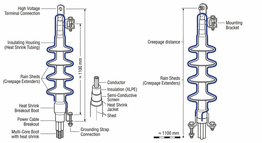
For a 35kV outdoor termination installed near a coastal facility, securing a total surface creepage distance exceeding 1,100 mm is standard practice. Outdoor heat shrink kits achieve this extended path through the addition of distinct rain skirts (often referred to as sheds). The geometry and downward-facing angle of these skirts are engineered specifically to break the continuous path of surface water and airborne contaminants, creating “dry bands” that effectively disrupt leakage currents. To formally classify environmental severity and verify necessary minimum creepage parameters, procurement teams should refer to IEC TS 60815-1:2025, the international framework governing insulator selection under polluted conditions.
Mitigating Clearance Constraints in the Field
When consulting the Complete Selection Map for Cable Accessories, engineers must balance the necessary creepage requirements with the physical, dimensional realities of the installation site.
A frequent field failure mode observed during project execution occurs when site personnel attempt to install heavily-skirted outdoor terminations inside confined indoor enclosures. Facing tight air clearances, installers sometimes compress the heat shrink rain skirts too closely together, or worse, manually trim the edges of the sheds to force a fit between narrow phase-to-phase barriers. This unauthorized field modification drastically reduces the effective creepage path, inviting moisture bridging and rapid dielectric breakdown upon energization. Proper engineering planning dictates verifying the physical dimensions of the switchgear or connection box before finalizing the kit specification, ensuring the chosen voltage class configuration can be installed cleanly without compromising clearances.
FIG-02:Diagram demonstrating creepage distance measurement across the rain skirts, a critical parameter that scales heavily with voltage class and pollution severity.
Indoor vs. Outdoor Termination Distinctions by Voltage
When specifying heat shrink terminations across any voltage class, differentiating between indoor and outdoor operating environments is just as critical as selecting the correct conductor size. A common and costly procurement error occurs when buyers assume a specific voltage rating universally qualifies a kit for any physical location. In reality, the material formulation and physical profile of the termination must directly match the specific environmental exposures it will face.
Indoor Switchgear Confined Spaces
Indoor terminations are engineered for controlled environments, such as inside substations, connection boxes, or metal-clad switchgear. Because these connections are shielded from direct precipitation and ultraviolet (UV) radiation, indoor kits prioritize a streamlined, low-profile design. For standard 10kV and 20(24)kV applications, indoor heat shrink terminations generally do not require rain skirts, relying instead on the inherent dielectric strength of the straight anti-tracking tubing to manage surface currents.
The primary engineering challenge indoors is spatial restriction. When terminating cables inside compact 12kV or 24kV switchgear panels, the available phase-to-phase and phase-to-ground clearances are strictly limited, sometimes measuring ≤ 120 mm depending on the specific enclosure design. Utilizing a bulky outdoor kit in this confined space significantly increases the risk of partial discharge due to compromised air gaps between the phases.
Outdoor UV and Weather Exposure
Conversely, outdoor terminations must survive decades of relentless exposure to UV light, driving rain, thermal cycling, and airborne pollutants. To combat these elements, outdoor kits utilize specialized, highly UV-resistant polymeric materials that resist molecular degradation and surface cracking over time.
Furthermore, outdoor kits are equipped with multiple heat-shrinkable rain skirts to manage leakage currents along the outer insulation surface. The application of these skirts scales predictably with system voltage: a standard 10kV outdoor termination typically employs a single skirt per phase, a 24kV termination utilizes three skirts, and a 35kV termination requires four or more skirts to reliably achieve the necessary creepage distance.
From a field diagnostic perspective, accidentally installing an indoor-rated termination in an outdoor environment is a fatal execution error. Without UV inhibitors and properly angled rain sheds, the smooth indoor tubing will rapidly succumb to severe surface tracking, leading to complete dielectric breakdown—often within the first year of energization. To prevent these specification gaps, procurement teams should strictly utilize a Cable Accessories RFQ Checklist to confirm that the physical environmental application explicitly matches the quoted voltage class design.
Core Component Verification Checklist Before Procurement
Incomplete specifications cause a significant portion of cable accessory site rejections. Procurement teams often inherit generic requirements, leading to situations where accessories arrive on site and problems surface during factory acceptance testing or after energization. To prevent this, buyers must utilize a rigorous verification framework before finalizing the purchase order. Relying solely on the voltage class is insufficient; a precise cable accessory specification sheet must capture the physical realities of the cable being terminated to translate international standards into actionable procurement language.
Conductor and Insulation Dimensional Verification
The most frequent mismatch occurs between the cable’s physical dimensions and the heat shrink kit’s recovery range. Kits are typically designed to cover a predetermined span of conductor sizes to reduce inventory complexity.
For example, a single 15kV termination kit might be rated for a conductor cross-section of 70–120 mm², while a larger variant covers 150–240 mm². However, specifying solely based on the conductor area introduces risk.
Engineers must verify the exact diameter over the primary insulation. If the actual cable insulation diameter is even 1.5 mm smaller than the heat shrink tubing’s fully recovered (shrunk) inner diameter, the material will not exert sufficient active compressive force. Field experience routinely demonstrates that this lack of radial pressure prevents the internal hot-melt mastic from forming a secure, watertight seal. As the cable undergoes daily thermal cycling and expands or contracts, moisture readily bypasses the compromised seal, leading to tracking and eventual dielectric failure.
Earthing System and Screen Interface Requirements
Procurement teams must also explicitly confirm the cable’s metallic screen configuration. Medium voltage cables typically utilize either a copper wire screen or a copper tape screen. The termination kit must include the correct grounding accessories—specifically constant force springs and properly sized tinned copper braids—matched exactly to the screen type.
A common execution error occurs when a kit designed for a wire screen is forced onto a tape screened cable. This mismatch forces installers to improvise ground connections in the field, frequently resulting in high-resistance joints that overheat or completely burn off during transient fault current conditions. By systematically verifying the conductor size, primary insulation diameter, screen type, and intended installation environment, procurement professionals eliminate the specification gaps that trigger project delays.
[Expert Insight] Field Verification Protocol
Measure the cable insulation diameter immediately after carefully peeling the semi-conductive layer to ensure the most accurate measurement for kit compatibility.
Always visually confirm that constant force springs match the exact screen type (wire vs. tape) before application to prevent high-resistance, heat-generating ground faults.
Cross-reference the accessory kit’s published recovery range against the specific cable manufacturer’s datasheet prior to scheduling the installation outage.
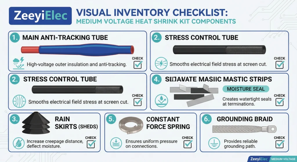
FIG-03:A standard medium voltage heat shrink kit requires specific components, including stress control tubing, environmental sealing mastic, and grounding hardware matched to the screen type.
Securing the Right Heat Shrink Cable Accessories for Your Project
Specifying heat shrink terminations strictly by voltage class is a foundational step, but as field data demonstrates, it is rarely sufficient to guarantee long-term reliability. A 24kV system demands careful coordination of insulation thickness, stress control mechanisms, and environmental clearances that a simple part number cannot fully capture. To prevent site rejections and premature dielectric failures, procurement and engineering teams must evaluate the complete physical reality of the installation environment. Proactive specification prevents the costly delays associated with mismatched equipment arriving at the project site.
Before issuing a purchase order, ensure your technical documentation accounts for the cable’s primary insulation diameter, the specific screen interface, and the exact dimensional constraints of your switchgear or pole-mounted arrangement. By bridging the gap between international standard ratings and practical site conditions, you mitigate the risk of high-resistance faults and costly distribution outages.
For technical support on your next distribution network upgrade or substation commissioning, explore our comprehensive range of cable accessories and transformer accessories to find the exact engineering match for your system. Engaging with specialized manufacturing engineering teams during the RFQ phase ensures that every critical parameter—from 1kV environmental seals to 35kV stress control profiles—is verified before manufacturing begins.
Frequently Asked Questions
How does voltage class dictate the number of rain skirts on an outdoor termination?
Outdoor terminations typically require 1 to 4 rain skirts depending on the system voltage—usually 1 for 10kV, 3 for 24kV, and 4 or more for 35kV applications—to properly manage surface tracking. This skirt count strictly scales with the voltage class and local pollution severity, though heavily contaminated marine environments may necessitate uprating the kit configuration to achieve longer creepage distances.
Can I use a 24kV heat shrink termination kit on a 10kV cable system?
While a 24kV kit possesses superior dielectric strength and will safely terminate a 10kV cable from an electrical standpoint, it is generally an uneconomical over-specification. Furthermore, the larger physical footprint and longer termination length of the 24kV kit frequently introduce severe clearance issues inside standard, compact 10kV indoor switchgear compartments.
What is the typical shelf life of medium voltage heat shrink kits?
Heat shrink termination kits typically offer a reliable shelf life of 2 to 5 years when stored in temperature-controlled environments, usually maintained between 10°C and 40°C. Actual viability depends entirely on preventing continuous ultraviolet exposure and moisture ingress during warehouse storage, as degraded hot-melt adhesive linings will compromise the final environmental seal upon field installation.
How does altitude affect heat shrink termination voltage class selection?
Installations exceeding 1,000 meters in altitude experience reduced air density, which typically lowers the dielectric flashover voltage by approximately 1 percent per 100 meters of additional elevation. To compensate for this environmental dielectric derating, engineers must often select a termination kit rated for the next highest voltage class, such as utilizing a 24kV kit on a 15kV system operating at high altitude.
Why do 35kV heat shrink kits require more complex stress control mechanisms than 1kV kits?
A 35kV system generates significantly higher electrical stress at the cable screen cut-back, often exceeding 3 to 5 kilovolts per millimeter, compared to the relatively negligible electrical stress found in 1kV systems. This extreme gradient necessitates dedicated high-permittivity stress control tubing and specialized mastics in 35kV kits to safely refract the electric field, whereas 1kV kits focus primarily on robust physical protection and basic moisture sealing.
yoyo shi
Yoyo Shi writes for ZeeyiElec, focusing on medium-voltage accessories, transformer components, and cable accessory solutions. Her articles cover product applications, technical basics, and sourcing insights for global electrical industry buyers.