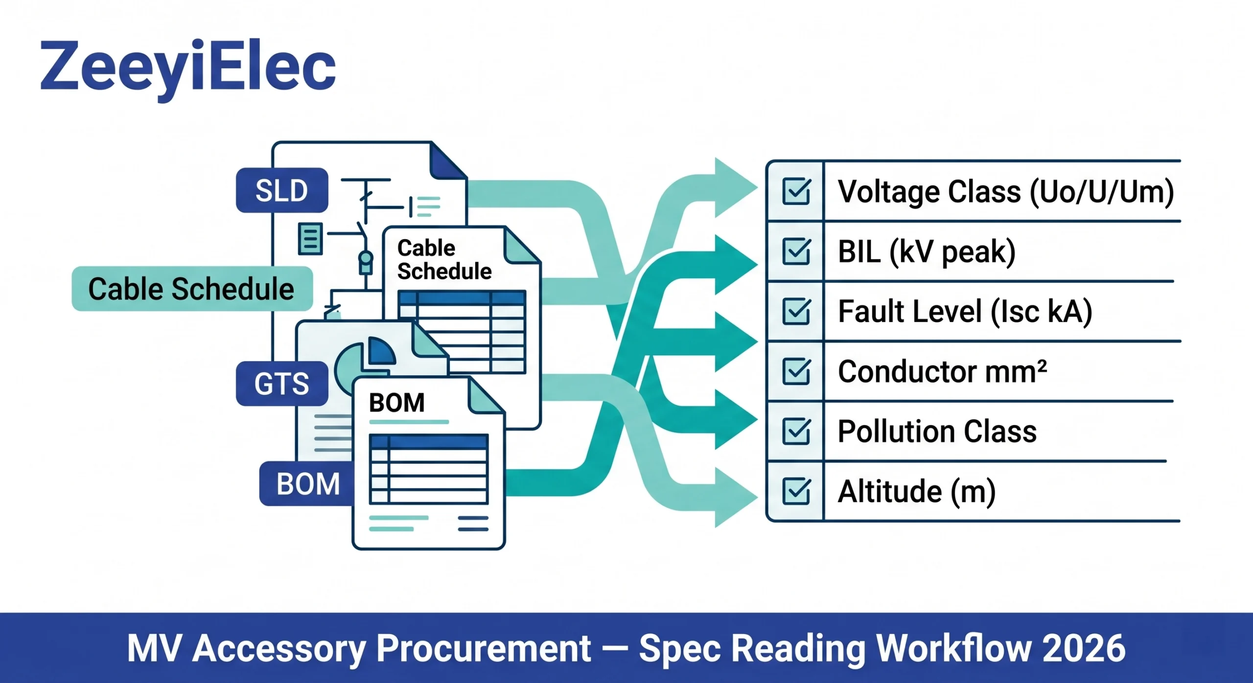
Reading a medium-voltage accessory project specification correctly requires extracting six parameter groups voltage class, fault level, conductor dimensions, environmental conditions, BIL, and standards compliance from four separate document layers before an RFQ is issued. Missing any one group produces accessories that fail site acceptance regardless of manufacturing quality.
Procurement teams routinely treat a project specification as a product filter a document that narrows down which catalogue item to order. That framing is the first mistake. A project specification is a system document: it encodes voltage architecture, fault behaviour, environmental exposure, and installation constraints simultaneously. Field data consistently shows that 30–40% of site rejections trace back to incomplete or misinterpreted specifications rather than manufacturing defects.
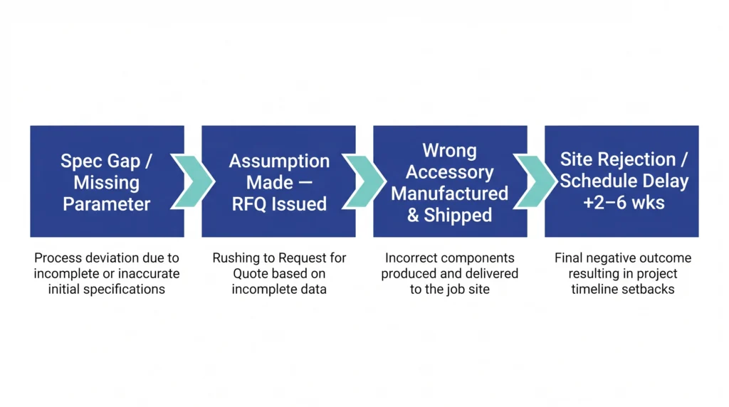
The Specification Gap Failure Chain
The failure pattern follows a predictable sequence. A spec parameter is ambiguous or missing. The procurement team makes a reasonable assumption. The accessory is manufactured and shipped. During factory acceptance testing or worse, after site installation the mismatch surfaces. At that point, the replacement cycle adds 2–6 weeks to the project schedule depending on lead time for the corrected item.
One recurring field case: a 15 kV cold shrink termination kit specified for a 95 mm² conductor arrives on site for a 150 mm² cable. Both fall within the “10–35 kV” voltage range stated in the general technical specification, but the inner diameter tolerance of the cold shrink tube is dimensioned for 95 mm² geometry. The accessory cannot be installed correctly. The conductor cross-section was listed in the cable schedule appendix a section many procurement engineers never open.
The specification gap failure chain: a missing or misread parameter propagates through assumption, manufacture, and shipment before surfacing as a site rejection that adds 2–6 weeks to the project schedule.
The Anatomy of a Project Specification Package for MV Accessories
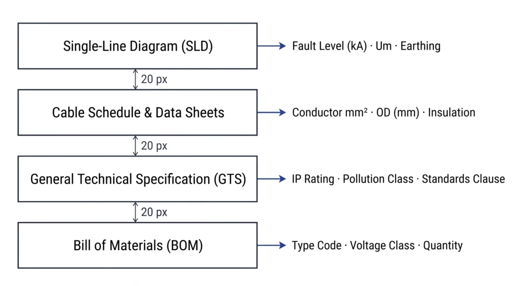
No single document contains all the parameters needed to procure MV accessories correctly. The specification is distributed across at least four document types, each carrying information the others do not duplicate. Engineers who read only the general technical specification the most commonly reviewed layer routinely miss dimensional data, fault levels, and environmental riders sitting elsewhere.
Single-Line Diagrams (SLD)
The SLD is the primary source for system-level electrical parameters. Extract: system voltage (nominal and maximum Um), neutral earthing configuration (solidly earthed, resistance earthed, or isolated neutral), and prospective fault level at the point of supply typically expressed in kA symmetrical. For distribution transformer applications, fault levels at the MV bus commonly range from 5 kA to 31.5 kA, a spread that directly controls fuse interrupt rating selection.
Cable Schedules and Data Sheets
The cable schedule carries dimensional and material parameters that determine physical compatibility. Extract conductor cross-section (mm²), insulation material (XLPE or EPR), insulation screen construction, and nominal outer diameter with tolerance band. Cold shrink and heat shrink termination kits are dimensioned to specific conductor and overall diameter ranges a kit designed for 95–240 mm² conductors will not install correctly on a 300 mm² cable even if the voltage class matches.
General Technical Specifications (GTS)
The GTS states the contractual standards framework: which IEC publication governs acceptance testing, what temperature class applies, and what environmental category the installation falls under. For outdoor MV cable terminations, the GTS typically specifies IP rating commonly IP65 for sealed outdoor installations and UV resistance requirements.
Bill of Materials and Equipment Lists
The BOM provides type codes, quantities, and sometimes manufacturer reference numbers. Cross-check BOM voltage class designations against the SLD. Discrepancies between these two documents are more common than expected on projects where the BOM was generated early and the SLD was revised later.
A project specification package for MV accessory procurement comprises four distinct document layers, each carrying non-overlapping parameter groups essential for accessory compatibility verification.
[Expert Insight] — What Experienced Procurement Engineers Check First
Cross-reference the BOM voltage class against the current SLD revision date mismatches are most common when the SLD was updated after the BOM was issued.
Cable schedule outer diameter tolerances are rarely checked at RFQ stage; they determine cold shrink fit more reliably than voltage class alone.
When the GTS references an environmental survey rather than stating a pollution class directly, treat this as a mandatory document request before issuing any RFQ line item.
A spec package without a fault level study appended is incomplete raise this as a formal clarification request, not an assumption.
Decoding Voltage Class and Insulation Parameters
Voltage class is the parameter that appears most frequently in MV accessory procurement documents and is most frequently misread. The confusion originates in notation: technical packages, IEC standards, and accessory catalogues each use different voltage expressions for what is nominally the same system. Reconciling them before issuing an RFQ prevents the most common class of accessory incompatibility.
Uo/U/Um Notation and What Each Value Controls
IEC voltage designation follows a three-value format: Uo/U(Um). Uo is the rated power-frequency voltage between conductor and earth the value that controls insulation thickness and phase-to-earth withstand requirement. U is the rated voltage between conductors. Um is the maximum system voltage, defining the upper continuous operating limit the accessory must withstand without degradation.
Realistic distribution network designations follow standard steps. Common values in MV accessory procurement include: 6/10(12) kV, 8.7/15(17.5) kV, 18/30(36) kV, and 26/35(40.5) kV. A termination kit specified for Um = 17.5 kV is not interchangeable with one rated Um = 12 kV, even though both are loosely described as “medium voltage” in non-technical procurement language.
Authority reference: IEC 60071-1 governs insulation coordination principles and defines the relationship between Um and required withstand levels for equipment selection.
BIL Cross-Check Against Accessory Catalogue
Basic Impulse Insulation Level (BIL) is expressed in kV peak and represents the impulse voltage the accessory must withstand without flashover or puncture. Project technical packages state a required BIL; accessory catalogues list a rated impulse withstand voltage. These must match or the catalogue value must exceed the specification requirement.
For a 15 kV class system (Um = 17.5 kV), the standard BIL is typically 95–110 kV peak. For a 35 kV class system (Um = 40.5 kV), BIL commonly reaches 170–200 kV peak. Specifying a termination kit with a 95 kV BIL on a system requiring 110 kV creates a latent failure risk that may not surface until the next lightning event or switching transient.
Procurement teams working from older BOMs sometimes carry forward a 95 kV BIL entry into a project where the updated insulation coordination study specifies 110 kV. Checking BIL against the current protection coordination document not the BOM alone catches this before manufacturing.
Voltage Class Alignment Reference
Classe de tension du système
Um (kV)
Typical BIL (kV peak)
Accessory Catalogue Check
10 kV class
12
75–95
Confirm rated impulse ≥ 95 kV
Classe 15 kV
17.5
95-110
Confirm rated impulse ≥ 110 kV
30 kV class
36
150–170
Confirm rated impulse ≥ 170 kV
35 kV class
40.5
170-200
Confirm rated impulse ≥ 200 kV
Cross-referencing this table against both the project GTS and the accessory catalogue rated impulse voltage eliminates the most common voltage class mismatch in medium-voltage cable accessory procurement. For transformer-side accessories including bushings and fuse assemblies, the same Um and BIL logic applies consult the guide de sélection des accessoires pour transformateurs for bushing-specific voltage class mapping.
Reading Protection and Fault Parameters for Transformer Accessories
Voltage class determines whether an accessory can operate in the system. Fault parameters determine whether it can protect the transformer when something goes wrong. Both parameter groups are mandatory; neither substitutes for the other.
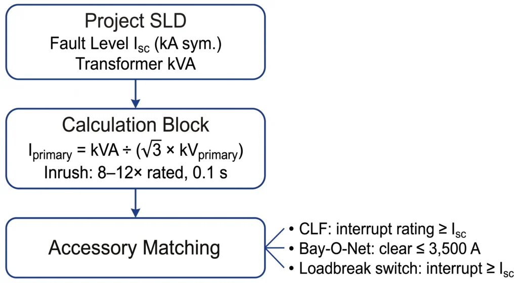
Fault Level (Isc) — The Most Misread Parameter
Prospective fault current, abbreviated Isc, is stated in kA symmetrical on the SLD, typically at the MV busbar. For distribution transformer applications, realistic values range from 5 kA at the end of a long rural feeder to 31.5 kA at a substation bus directly fed from a large grid transformer. A current limiting fuse (CLF) rated for 20 kA symmetrical installed on a bus with 31.5 kA prospective fault current will not clear the fault safely.
The misread occurs when procurement teams confuse prospective fault current with let-through current after the CLF operates. Accessory selection must reference the prospective value the worst-case condition the fuse must survive and interrupt.
Transformer kVA Rating and Primary Current for Fuse Sizing
Fuse selection begins with deriving nominal primary current from the kVA rating and primary voltage: Iprimary = kVA ÷ (√3 × kVprimary) for three-phase transformers. A 500 kVA three-phase transformer on a 15 kV primary produces approximately 19.3 A nominal primary current. A 1,000 kVA unit on the same voltage produces approximately 38.5 A. Current limiting fuses must be sized to carry nominal current continuously while remaining selective against inrush typically 8–12× rated current for durations up to 0.1 seconds during transformer energisation.
When inrush multiplier is absent from the procurement document, engineering practice treats 10× rated current at 0.1 s as a conservative starting point for CLF minimum melting time coordination. The transformer test report should confirm the actual inrush profile before finalising fuse selection for distribution transformer protection.
Switch Interrupting Duty vs. Fault Level
Loadbreak switches carry two separate current ratings that must each be checked: continuous load current rating and fault interrupting capability. A switch rated 630 A continuous with 10 kA fault interrupting capacity is correctly applied only where prospective fault current does not exceed 10 kA. If the technical package states 12.5 kA, the switch is underrated for fault duty regardless of its load current margin.
Technical packages sometimes list switchgear interrupting ratings in MVA rather than kA. Convert using: Isc (kA) = MVAfault ÷ (√3 × kVsystem). For a 250 MVA fault level on a 15 kV system: Isc = 250 ÷ (1.732 × 15) ≈ 9.6 kA symmetrical. Always convert to kA before comparing against accessory interrupt ratings.
For Bay-O-Net fuse assemblies used in coordination with CLFs, the technical package should also state the maximum fault current the Bay-O-Net element is expected to clear typically below 3,500 A, with higher fault levels handled by the backup CLF. The Série d'assemblage de fusibles Bay-O-Net page covers interrupt coordination parameters in detail.
Fault parameter extraction follows a three-stage dependency chain: prospective fault level and transformer kVA are extracted from the SLD, converted to primary current and inrush envelope, then matched against CLF interrupt rating, Bay-O-Net clearing capacity, and loadbreak switch fault duty.
[Expert Insight] — Fault Parameter Checks That Prevent Site Rejection
Always confirm whether fault level stated in the technical package is at the HV bus or at the transformer secondary these differ significantly and the wrong reference produces an undersized fuse.
Inrush multiplier is rarely stated explicitly in distribution transformer specs; 10× at 0.1 s is a conservative working assumption, but request the transformer factory test report for units above 1,000 kVA.
Bay-O-Net and CLF coordination requires both devices to be specified together procuring one without confirming the other’s interrupt boundary creates a protection gap.
Reading Environmental and Installation Conditions
Electrical parameters define whether an accessory is compatible with the system. Environmental parameters define whether it will survive the site. A termination kit with correct voltage class and BIL will fail prematurely if its creepage distance is undersized for the pollution level, or if its dielectric strength is not derated for high-altitude installation. These conditions appear in technical packages often in appendices that procurement teams treat as background reading rather than mandatory extraction targets.
Déclassement d'altitude
Most MV accessory designs are type-tested at altitudes up to 1,000 m above sea level. Sites above this threshold require either explicit manufacturer confirmation that the accessory is rated for the installation altitude, or selection of an accessory with a higher BIL than the base insulation coordination study requires.
A commonly applied correction reduces dielectric withstand capability by approximately 1% per 100 m above 1,000 m. A site at 2,000 m carries a 10% dielectric derating relative to sea-level type-test conditions. A termination kit with a rated BIL of 110 kV peak at sea level operates at approximately 99 kV peak equivalent withstand at 2,000 m below the 110 kV requirement if no uprating is applied.
A substation project at 1,800 m elevation specified 15 kV cold shrink terminations using standard sea-level BIL values. The altitude clause sat in Appendix C of the GTS unreviewed during RFQ preparation. Accessories arrived with 110 kV BIL; replacement kits with manufacturer-confirmed altitude rating were sourced before energisation, adding three weeks to the schedule. The clause was present; it was not read.
Pollution Degree and Creepage Distance
Extract pollution class from the GTS environmental section, not from the SLD. SLDs rarely carry pollution data. When the GTS references a site environmental survey rather than stating a class directly, request the survey document before issuing the RFQ.
IEC pollution severity levels map to minimum specific creepage distances: light pollution (Class I/II) requires approximately 16–20 mm per kV of Um; medium pollution (Class III) requires 25 mm/kV; heavy industrial or coastal pollution (Class IV) requires 31 mm/kV or greater. For a 35 kV class accessory (Um = 40.5 kV) in a Class IV environment, minimum creepage reaches 40.5 × 31 ≈ 1,255 mm a requirement that eliminates standard catalogue items and requires explicit supplier confirmation.
Indoor vs. Outdoor Designation and IP Rating
Outdoor cold shrink terminations require UV-stable silicone formulations and weathershed geometry. Heat shrink terminations for outdoor use require adhesive-lined mastic sealing layers at the cable entry point. The IP rating commonly IP54 for sheltered outdoor and IP65 for exposed locations confirms the sealing standard the accessory must meet. For technology selection in outdoor environments, the cold shrink cable accessories series covers UV resistance and installation temperature range parameters that interact directly with site environmental classification.
The MV Accessory Spec-Reading Workflow — Step by Step
The data needed for MV accessory procurement is distributed across multiple documents, written in different notation conventions, and sometimes contradicted between document revisions. The following six-step sequence extracts parameters in order of dependency each step produces outputs that inform the next.
Step 1 — Locate the Master Voltage Designation
Open the SLD first. Identify system voltage in Uo/U(Um) format. If the SLD states only a nominal voltage, cross-reference the GTS to confirm Um. Record all three values and flag any discrepancy between the SLD voltage label and the GTS voltage class statement revisions frequently update one without the other.
Step 2 — Extract Fault Level and Earthing Method
From the SLD protection schedule or appended fault level study, record prospective Isc in kA symmetrical and neutral earthing method. These two values together determine the required insulation class for transformer-side accessories and the interrupt rating floor for fuse and switch selection. If fault level is stated in MVA, convert to kA before proceeding.
Step 3 — Pull Cable Schedule Data
Extract conductor cross-section (mm²), insulation material, screen construction type, and nominal outer diameter with tolerance. Match these against the accessory manufacturer’s dimensional compatibility table not the voltage class table alone. A 150 mm² XLPE and 150 mm² EPR cable of the same voltage class may require different termination kits due to insulation outer diameter differences of 2–4 mm.
Step 4 — Map Environmental Conditions
From the GTS environmental section and any appended site data sheet, record: site altitude in metres, pollution class, indoor/outdoor designation, and IP rating. Apply altitude derating logic if site elevation exceeds 1,000 m. Flag Class IV or coastal pollution designations for extended creepage distance confirmation.
Step 5 — Cross-Check BIL and Creepage Against Accessory Catalogue
With Um, BIL requirement, and creepage distance calculated, verify three values simultaneously against the catalogue: rated impulse withstand voltage meets or exceeds specified BIL; rated Um meets or exceeds system Um; specific creepage distance meets or exceeds pollution class requirement. All three must pass partial compliance is non-compliance for type-tested MV accessories.
Step 6 — Flag Gaps and Raise RFQ Clarification Points
Any parameter that cannot be confirmed from available documents becomes a mandatory clarification point before the RFQ is issued. Common gaps: fault level not stated on SLD, altitude not specified in GTS, cable outer diameter listed without tolerance, BIL not updated after insulation coordination study revision. Document each gap explicitly in the RFQ cover note.
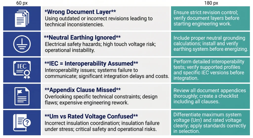
Common Spec-Reading Mistakes and How to Avoid Them
Specification misreading follows recognisable patterns. The same five mistakes appear across projects of different scale, geography, and procurement team experience level.
Mistake 1 — Reading System Voltage from the Wrong Document Layer
The transformer nameplate, SLD voltage label, and cable schedule Uo/U(Um) designation are not guaranteed to agree particularly on projects where documents were generated at different design stages. The cable schedule Uo/U(Um) designation is the controlling value for accessory insulation class. A 10 kV nominal system on an isolated neutral network requires accessories for full phase-to-phase voltage during a single-phase fault not the solidly earthed class where Uo = 5.8 kV.
Neutral earthing method is recorded on the SLD, often as a small symbol at the transformer neutral point. Solidly earthed, resistance earthed, and isolated neutral systems require different Uo ratings for the same nominal voltage an oversight that accounts for a disproportionate share of accessory incompatibility on international projects.
Mistake 3 — Treating IEC Compliance as Interoperability Confirmation
An accessory certified to IEC standards and a technical package referencing IEC standards do not automatically produce a compatible combination. IEC standards define test methods and minimum performance thresholds not dimensional interchangeability between manufacturers or compatibility with a specific cable construction. Compliance confirms a performance floor; it does not confirm site fit.
Mistake 4 — Missing Altitude and Pollution Clauses in Appendices
Environmental conditions are contractually binding when stated in any section of the technical package, including appendices distributed separately from the main GTS.
A pollution class upgrade from Class II to Class III increases minimum required creepage distance from approximately 20 mm/kV to 25 mm/kV of Um. For a 35 kV class accessory (Um = 40.5 kV), this represents a minimum creepage increase from 810 mm to 1,012 mm a difference that separates standard catalogue items from extended-profile variants.
Mistake 5 — Confusing Um with Rated Voltage in Catalogue Matching
Accessory catalogues express voltage rating inconsistently some list nominal system voltage, others list Um, others list the full IEC designation string. Always confirm which convention the catalogue uses before populating the order. When uncertain, request the accessory’s full IEC type test certificate it will state Um explicitly in the test conditions.
Five recurring specification misreading errors — from incorrect voltage document sourcing to catalogue notation confusion — each paired with a single corrective action applicable before RFQ submission.
Where to Go After Reading the Spec — Procurement Action Path
A completed spec-reading pass produces a parameter set, not a purchase order. The extracted values voltage class, fault level, conductor cross-section, environmental conditions, and BIL requirement need to be transferred into a structured RFQ before a supplier can quote accurately. An unstructured list produces a quotation that cannot be validated against the technical package.
The two most common failure points at this stage are parameter omission and format mismatch. Structured RFQ documentation eliminates both. For transformer accessory procurement: bushings, tap changers, fuse assemblies, and loadbreak switches, the parameter transfer framework is covered in the Transformer Accessories RFQ Checklist. For cable termination and jointing kits, the equivalent framework is at the Liste de contrôle de l'appel d'offres pour les accessoires de câbles. Both checklists map directly to the six parameter groups this article covers.
Submit your extracted parameters to ZeeyiElec’s engineering team for accessory matching, catalogue confirmation, and quotation. Technical response is provided without obligation. Contact the team at zeeyielec.com/contact.
Questions fréquemment posées
What is the most important parameter to extract from an MV project spec for cable accessory selection?
The voltage designation (Uo/U/Um) and conductor cross-section are the two non-negotiable starting points getting Um wrong by one voltage class produces a completely incompatible accessory, and an incorrect conductor diameter means the termination kit cannot be physically installed regardless of electrical rating.
How do I find the fault level in a project specification document?
Fault level (Isc in kA symmetrical) is typically stated in the protection coordination study or on the single-line diagram near the busbar, if absent, request it formally before issuing any RFQ, as it directly controls fuse interrupt ratings and switch fault duty selection.
What does BIL mean in a transformer accessory specification, and how do I match it?
BIL (Basic Impulse Insulation Level) is expressed in kV peak and represents the impulse withstand capability of the accessory for a 15 kV class system, a typical BIL of 95–110 kV peak should be confirmed against the accessory catalogue’s rated impulse voltage before ordering.
Why does the earthing method affect MV accessory selection for the same nominal voltage?
Neutral earthing determines the phase-to-earth voltage (Uo) on an isolated or high-impedance earthed network, a single-phase fault raises Uo to the full phase-to-phase level, requiring accessories rated for a higher voltage class than a solidly earthed system of identical nominal voltage.
How does site altitude affect which MV accessory I should specify?
Above approximately 1,000 m elevation, air dielectric strength decreases progressively, requiring either a higher BIL-rated accessory or written manufacturer confirmation of altitude derating acceptance the specific correction depends on altitude, insulation geometry, and accessory type.
When should I raise a formal clarification request instead of making a procurement assumption?
Raise a clarification request whenever any of these five parameters are missing or ambiguous: fault level (kA), neutral earthing method, site altitude above 1,000 m, pollution class, or cable outer diameter tolerance proceeding with assumptions on any of these carries a high probability of accessory incompatibility.
What is the difference between Um and rated voltage in an accessory catalogue?
Um is the maximum continuous system voltage the accessory must withstand, while a catalogue’s “rated voltage” may reference nominal class rather than Um always verify the accessory Um meets or exceeds the project’s Um directly, since the nominal voltage label alone does not confirm this.
yoyo shi
Yoyo Shi écrit pour ZeeyiElec, en se concentrant sur les accessoires de moyenne tension, les composants de transformateurs et les solutions d'accessoires de câbles. Ses articles couvrent les applications des produits, les bases techniques et les perspectives d'approvisionnement pour les acheteurs de l'industrie électrique mondiale.