A bushing well interface is the standardized mating boundary where a transformer-mounted bushing well and a removable bushing insert seat together to form a sealed, electrically continuous separable connection. Both halves must conform on the same interface plane — get it right and the connection is watertight and dielectrically sound; get it wrong and nothing else on the datasheet matters.
What Is a Bushing Well Interface?
In a distribution transformer, the bushing well is the fixed component bonded to the tank wall, while the bushing insert (or separable connector) is the half that lands the cable side. They belong to the same separable insulated connector family, which is why dimensional conformance — not brand — governs whether they pair correctly. This interface is most common at the 200 A continuous current class, across system voltage classes of 15, 25, and 35 kV.
The two mating halves
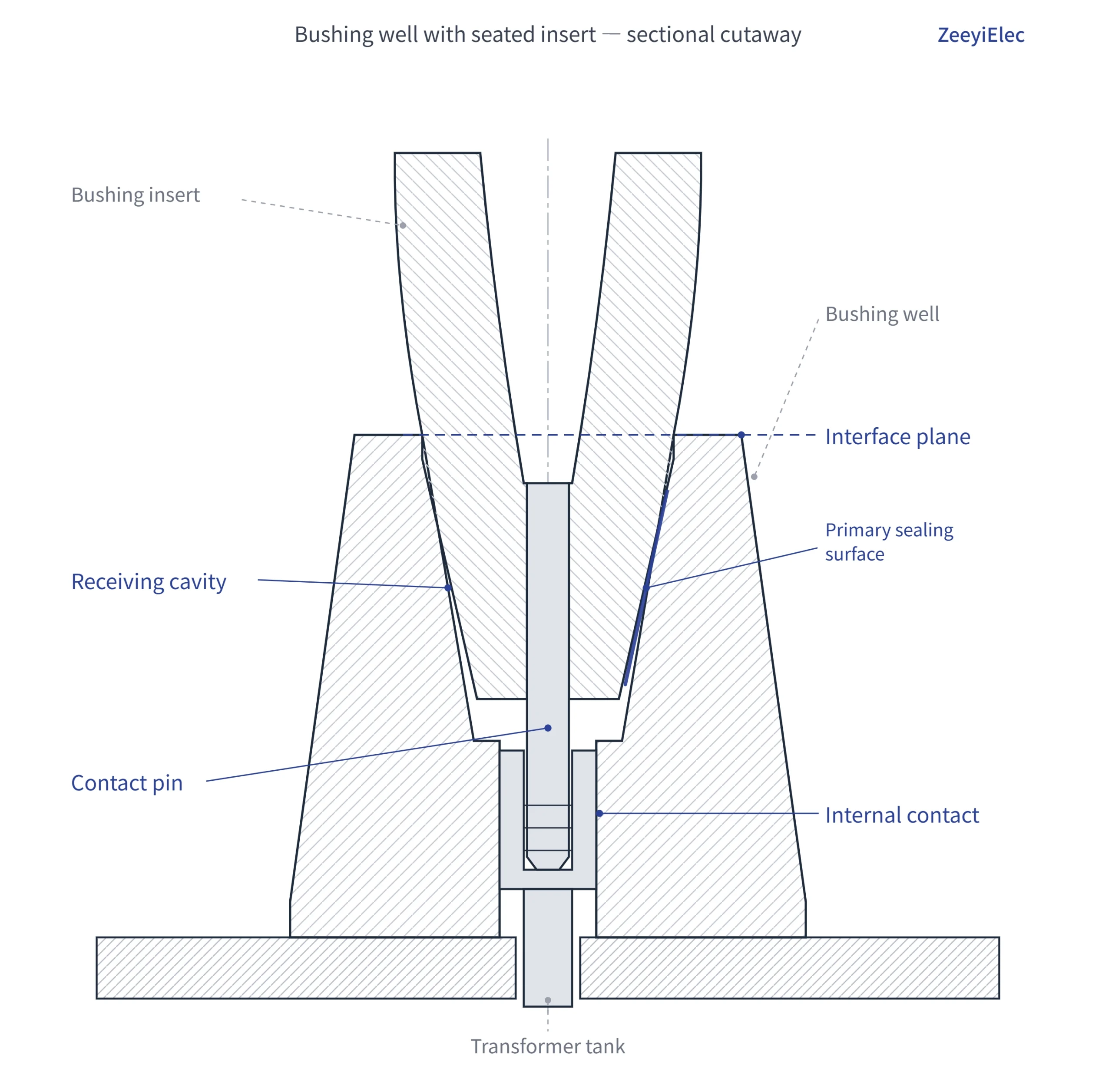
The well provides the receiving cavity, the internal contact, and the primary sealing surface. The insert provides the contact pin, the matching sealing land, and the semiconductive shield that carries the screen continuously across the joint. Three things must travel together: the geometry that controls fit, the surfaces that control sealing, and the shield path that controls electrical stress. A well built for one interface class will physically reject — or worse, partially accept — an insert from another.
Why “interface” is the operative word
Specifying a bushing well by voltage alone, then assuming any 200 A insert will land, is a common error. The controlling detail is the interface designation, which fixes cavity depth, contact-pin engagement, and sealing-surface diameter as a coordinated set. Substituting a non-matching half shifts the dielectric stress field unpredictably.
Interface conformance is governed by a coordinated set of dimensions, not a single number. The controlling reference is the interface designation, which fixes how the well cavity and insert engage so fit, sealing, and electrical stress all stay within design intent. In North American practice this interface family is defined by IEEE Std 386-2016, which establishes ratings and interchangeable construction features for separable insulated connector systems on distribution systems rated 2.5 kV through 35 kV and 900 A or less. Review the scope at the IEEE Standards Association record for IEEE 386.
The five dimensions that must conform between a bushing well and insert—interface class, cavity depth, sealing-surface diameter, voltage class, and current class.
Must-match parameter table
Paramètres
What it controls
Realistic class/range
Why it must match
Interface class/profile
Overall mating geometry
200 A or 600 A class
A mismatched profile prevents seating or seats only partially
Cavity depth & pin engagement
Contact pressure and continuity
Set by interface class
Short engagement raises contact resistance and local heating
Sealing-surface diameter
Watertight interference fit
Set by interface class
Under/over-sized lands break the moisture seal
Classe de tension
Insulation thickness, creepage
15 / 25 / 35 kV
Drives BIL coordination, typically 95–150 kV
Continuous current class
Thermal capacity
200 A continuous (typical)
Over-duty accelerates thermal aging
How the parameters interact
These five are not independent. The interface class effectively bundles cavity depth, pin engagement, and sealing-surface diameter into one designation, so matching the class usually resolves the mechanical dimensions in one step. Voltage and current class then sit on top as electrical qualifiers. Where a datasheet does not state the interface class, treat the pair as unverified rather than interchangeable — visual similarity between 200 A interfaces has misled more than one commissioning crew.
Interface Geometry & Sealing Surfaces — Why the Numbers Exist
Every dimension on the interface drawing serves a physical job: hold the conductor connection, exclude moisture, and keep the electric field controlled. That is why substituting a near-match half is risky rather than merely imperfect.
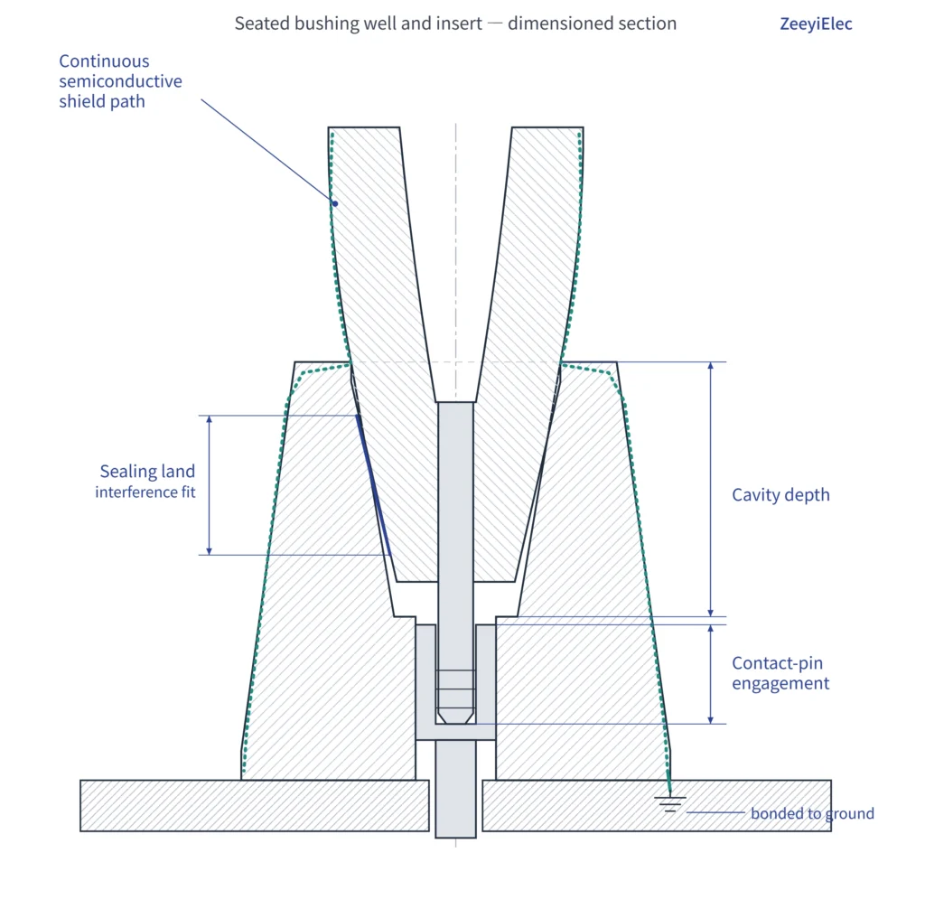
Cross-section of a mated separable interface, marking contact-pin engagement depth, the sealing land’s interference fit, and the semiconductive shield crossing the joint.
Cavity depth and contact pin engagement
The cavity depth and the insert’s contact-pin length are matched so the pin fully bottoms into the well’s internal contact. Full engagement delivers low, stable contact resistance and even current transfer at the 200 A continuous class. When engagement falls short, contact area drops and localized heating rises.
A properly engaged separable interface typically holds contact resistance in the low hundreds of micro-ohms (on the order of 100–300 μΩ); partial or misaligned engagement can push this several times higher, concentrating I²R heating at the contact and accelerating thermal aging.
Sealing surface and interference fit
The sealing land is sized for a deliberate interference fit between the insert’s elastomer and the well bore, making the joint watertight in buried or pad-mounted service. If the sealing diameter is off — even by a fraction of a millimetre because the halves come from different interface classes — the seal either won’t compress enough to exclude water or will be forced past its design strain.
Semiconductive shield continuity across the interface
A separable connector is a fully shielded, dead-front device, so the semiconductive layer must stay electrically continuous as it crosses from insert to well. The geometry exists to keep that screen unbroken and the field uniform.
A continuous shield holds partial discharge low — well-designed 15–35 kV interfaces are generally expected to show PD on the order of ≤ 3 pC at rated voltage. A geometry mismatch that interrupts the screen creates a local field enhancement where discharge initiates, the first step toward tracking and eventual breakdown.
[Expert Insight] Three physical checks before you trust an interface
Confirm the pin seats to a positive stop — no visible shoulder standoff.
Inspect the sealing land for grit, nicks, or lubricant on the wrong surface.
Verify the shield/screen is unbroken across the mated joint before capping.
When any of the three is in doubt, treat the interface as unverified.
Voltage Class & Current Class Compatibility
Once the mechanical interface class is confirmed, two electrical qualifiers decide whether the pair is fit for the system: voltage class and continuous current class. Both halves — and the apparatus they connect to — have to agree.
Matching voltage class (15/25/35 kV)
Bushing wells and inserts are offered in discrete voltage classes, most commonly 15, 25, and 35 kV for distribution work. The class sets insulation thickness, creepage distance, and the rated BIL. A 15 kV-class insert seated in a 25 kV-class well may mate mechanically yet leave the assembly under-insulated. The conservative practice is to specify well, insert, and connected cable accessory to a single voltage class. Near a class boundary, the LV-versus-MV bushing selection guidance helps frame the decision.
Matching continuous current class (200 A)
Separable interfaces are built around standard current classes — 200 A loadbreak being dominant for distribution bushing wells and inserts, with 600 A used for higher-duty connections. The 200 A class defines the thermal design of the contact and surrounding elastomer. Sustained operation above the rated continuous current accelerates thermal aging, so the insert’s current class must equal or exceed the circuit’s continuous load, with headroom for ambient and loading cycles.
When the bushing side also constrains the choice
The well lands against the transformer bushing interface on its other side. If the bushing follows a different standard family, the well selection must follow it. Bushing insulation requirements are governed by IEC 60137 for insulated bushings rated above 1000 V, and by ANSI/IEEE families on the North American side, so confirm which standard the apparatus follows before fixing the well. The medium-voltage bushing range shows how ANSI and DIN interfaces differ at this boundary — a difference that propagates straight into the well-and-insert decision.
Field Realities — Seating, Contamination & Mismatch Symptoms
Interface problems rarely announce themselves at install. They surface weeks or months later as heating, moisture, or partial discharge, so crews benefit from recognizing a marginal interface before energization.
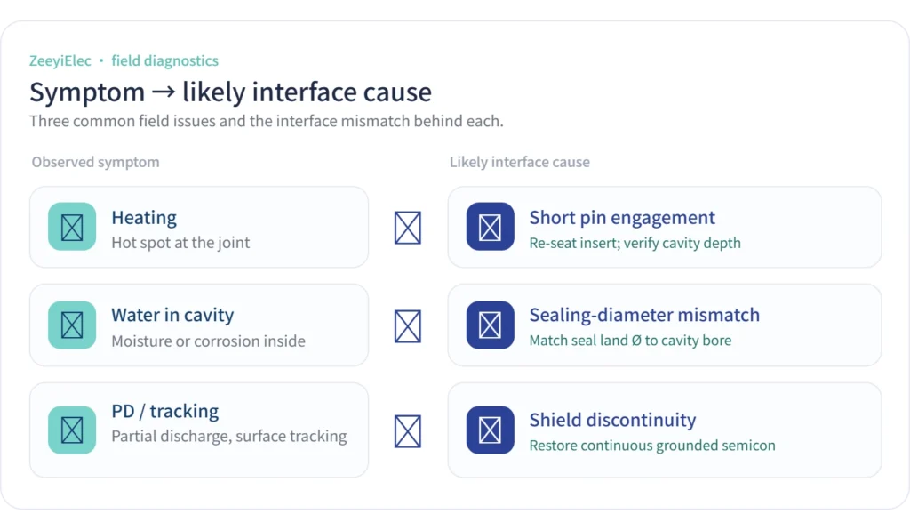
A field-diagnostic flow linking common symptoms—heating, water in cavity, partial discharge—to the likely interface cause behind each.
Incomplete seating and partial engagement
The most common field issue is an insert that looks installed but is not fully home. On one pad-mounted distribution unit, a separable elbow that felt seated by hand was later found about 6 mm short of full engagement; the joint ran noticeably warm under load, consistent with reduced contact area. Partial engagement can drive the contact 20–40 °C above ambient at full load — enough to age the surrounding elastomer prematurely. Seat to the manufacturer’s positive-stop indication and confirm the audible or tactile latch rather than judging by feel.
Moisture ingress and surface contamination
The sealing interference fit only works on clean, undamaged surfaces. During one commissioning check, light tracking on a 25 kV insert traced back to grit on the sealing land that had broken the watertight seal and admitted moisture. Contamination, misplaced lubricant, or a nicked elastomer all defeat the seal even when dimensions are correct. Keep the cavity capped until assembly, apply only the specified jointing compound, and inspect both surfaces under good light before mating.
What a dimensional mismatch looks like at energization
A true class mismatch — a 200 A insert forced toward a different interface profile — typically shows as a unit that will not seat fully, an unusually high mating force, or a visible standoff at the shoulder. Because consequences range from no immediate symptom to failure within months, a non-conforming or unverified pair should be treated as not ready for service.
As a field rule of thumb: if seating force feels abnormal or the shoulder does not close, stop. A separable interface that does not seat cleanly should be treated as a mismatch until the interface class and rating on both halves are confirmed against datasheets.
[Expert Insight] Habits that prevent late-life interface failures
Cap cavities and inserts until the moment of assembly.
Seat to positive stop, then re-check the shoulder is fully closed.
Record megohmmeter readings at commissioning as a baseline.
Treat any warm elbow found later as an interface check, not a cable fault.
Verifying Interface Compatibility Before Energization
Compatibility is confirmed on paper first and in the field second. A short, disciplined sequence catches mismatches while correction is still cheap.
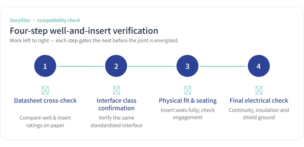
A four-step pre-energization sequence: datasheet cross-check, interface-class confirmation, physical fit and seating, then the final electrical check.
Desk verification (before the crew mobilizes)
Step 1 — Cross-check datasheets. Confirm the bushing well, the insert/connector, and the connected cable accessory all state the same voltage class (15, 25, or 35 kV) and current class (typically 200 A). A blank or ambiguous interface field means unverified, not compatible.
Step 2 — Confirm the interface designation. Match the published interface class on both halves rather than inferring it from a photograph. Where one datasheet omits it, request written confirmation before release. Treat this as the gate: nothing ships to site until the interface class is confirmed on both halves.
Field verification (at install and commissioning)
Step 3 — Physical fit and seating. Hand-fit the insert, watch for abnormal mating force, and seat to the positive-stop indication. A visible standoff is a stop-work signal.
Step 4 — Final electrical check. After seating, verify the assembly with the project’s pre-energization tests.
A typical pre-energization check confirms shield/screen continuity and insulation resistance with a megohmmeter at 2.5–5 kV DC, expecting a clean, stable reading (commonly ≥ 1000 MΩ for a sound MV interface, though acceptance limits should follow the project spec). A reading that drifts or reads low points back to moisture or a seating fault, not necessarily the cable.
Crews who treat Step 2 as a hard gate spend far less time later diagnosing warm elbows and water-in-cavity findings — problems that almost always trace back to an interface assumption no one verified.
Specify the Right Bushing Well & Insert Interface
Most interface failures are specification failures caught too late — and also the easiest to prevent, because the information needed fits on a single line of an RFQ. When you request a bushing well and insert, send the three parameters that decide compatibility: the interface class designation, the voltage class (15, 25, or 35 kV), and the continuous current class (typically 200 A). Add the connected cable size and the apparatus bushing standard, and a supplier can confirm a true match rather than guess from a model number.
If any of those fields are unknown, that is the conversation to have before ordering — not after a warm elbow shows up at commissioning. A short technical exchange up front replaces weeks of field diagnosis later.
ZeeyiElec’s engineering team can match the well-and-insert interface to your transformer and cable side, and supply the datasheet confirmation your QA process needs. Start a technical review through the bushing well and insert series, or, if your scope also covers the cable termination side of the same separable interface, the gamme d'accessoires pour câbles covers the mating half. Share your interface class, voltage, and current rating, and you will get a verified compatibility answer rather than an assumption.
Questions fréquemment posées
What dimensions must match between a bushing well and a bushing insert?
The mating interface profile, contact-pin engagement depth, sealing-surface diameter, voltage class, and continuous current class all must conform; exact values depend on the chosen interface class and system rating, so confirm both halves against their datasheets before ordering.
Can a 200 A bushing insert fit any bushing well?
Generally only when both share the same interface class and voltage rating, since a 200 A insert is built for a specific separable-connector interface; mixing ampere or interface classes typically prevents proper seating, so verify ratings on both components.
Are bushing well interfaces standardized across manufacturers?
The separable-connector interface family is broadly standardized, which often allows cross-brand mating within the same class — but tolerances, sealing details, and shielding can still vary, so a physical fit and seating check before energization remains advisable.
Does voltage class affect bushing well interface dimensions?
Voltage class (commonly 15, 25, or 35 kV) influences insulation thickness and creepage, which can change overall dimensions and the rated interface; selecting a well and insert in the same voltage class is the safest baseline.
What happens if the bushing well and insert dimensions don’t match?
Mismatch can cause incomplete seating, elevated dielectric stress, moisture ingress, or tracking, with consequences ranging from no symptoms at install to failure within months, so non-conforming pairs should not be energized.
How do I confirm compatibility before installation?
Cross-check both datasheets for matching interface class, voltage, and current rating, then perform a physical fit and seating verification on site; final confirmation should rest on the manufacturer’s stated interface designation rather than visual similarity.
Is the bushing well interface the same as a separable connector interface?
They belong to the same separable insulated connector family and share interface logic, but the well is the fixed transformer-mounted component while the insert is the mating half; compatibility still hinges on matching the same interface class and rating.
yoyo shi
Yoyo Shi écrit pour ZeeyiElec, en se concentrant sur les accessoires de moyenne tension, les composants de transformateurs et les solutions d'accessoires de câbles. Ses articles couvrent les applications des produits, les bases techniques et les perspectives d'approvisionnement pour les acheteurs de l'industrie électrique mondiale.