Was eine Abgriffreihe ist und warum Verteilungstransformatoren eine benötigen
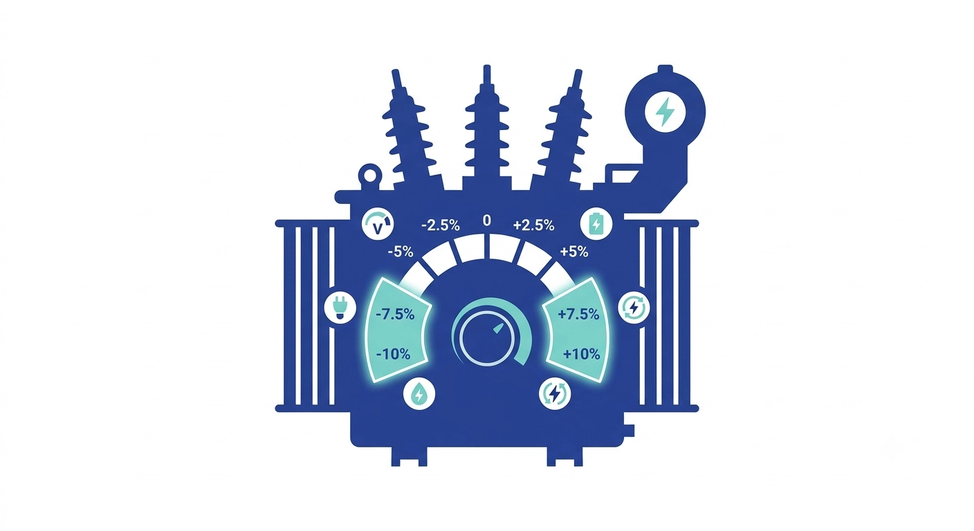
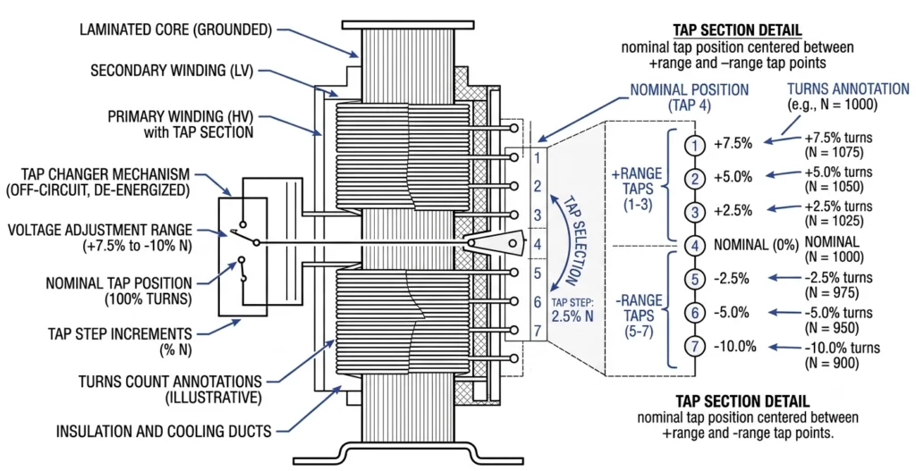
Der Schaltbereich bei Verteiltransformatorprojekten bestimmt, in welchem Umfang ein Stufenschalter die Sekundärspannung bei schwankenden Versorgungsbedingungen korrigieren kann. Bei den meisten Verteiltransformatoren erstreckt sich dieser Bereich von ±5% bis ±10% der Nennspannung und ist in eine feste Anzahl diskreter Schaltstufen unterteilt, anstatt eine stufenlose Einstellung zu ermöglichen. Der Mechanismus legt eine feste Korrektur des Übersetzungsverhältnisses fest, die bis zur nächsten geplanten Abschaltung bestehen bleibt – er regelt die Spannung unter Last nicht dynamisch, was die Aufgabe eines Laststufenschalters bei Leistungstransformatoren ist.Die Primärwicklung verfügt über mehrere Anzapfstellen, von denen jede eine leicht unterschiedliche Anzahl von Windungen verbindet. Durch die Auswahl einer Anzapfstelle näher am Anfang oder Ende der Wicklung wird das effektive Windungsverhältnis verschoben, wodurch die Sekundärspannung um einen bekannten Wert nach oben oder unten verlagert wird. A ±5% Das Fenster bietet in der Regel fünf Positionen in 2.5% Schritte; a ±10% Das Fenster erstreckt sich oft über fünf Positionen 5% Schritte, wobei dies je nach Hersteller und kVA-Klasse variiert.
Ein Transformator in der Nähe des Umspannwerks weist in der Regel eine höhere Spannungsstabilität auf als einer am Ende einer langen Zuleitung, wo der Spannungsabfall bei Spitzenlast die Sekundärspannung ohne ausgleichende Anpassung außerhalb der zulässigen Grenzen treiben kann. Wird dieser Wert bereits in der Planungsphase falsch gewählt, lässt sich dies vor Ort nicht mehr korrigieren – die Wicklungsabgriffe werden bei der Herstellung festgelegt, sodass ein zu klein bemessenes Fenster keinen Spielraum für die tatsächlichen Bedingungen vor Ort lässt, während ein zu groß bemessenes Fenster unnötige Komplexität bei der Wicklung und zusätzliche Kosten verursacht.
Jeder Abgriff verbindet eine unterschiedliche Anzahl von Wicklungswindungen, wodurch der Stufenschalter das effektive Windungsverhältnis in festen prozentualen Schritten verändern kann.
Bereich vs. Schrittweite vs. Anzahl der Positionen
Der Bereich ist das prozentuale Gesamtfenster (zum Beispiel, ±5%). „Step“ ist der Abstand zwischen benachbarten Positionen (zum Beispiel, 2.5%). Die Positionszahl ergibt sich aus der Summe beider Werte – eine ±5% Fenster bei einem 2.5% Dieser Schritt ergibt fünf Positionen.
Wesentliche Eingaben, die das erforderliche Anpassungsfenster bestimmen
Bevor eine prozentuale Angabe in eine Spezifikation aufgenommen wird, müssen Daten aus vier Kategorien erhoben werden.
Spannungsschwankungen auf der Versorgungsseite
Die Primärspannung an einer Verteilungsleitung kann um ±5% zu ±8% der Nennspannung über einen täglichen Lastzyklus hinweg; bei Zuleitungen mit intensiver industrieller Schaltaktivität oder saisonaler Pumpenbetrieb ist die Schwankungsbreite größer. Dies sollte auf der Grundlage einer tatsächlichen Spannungsmessung am Anschlusspunkt ermittelt werden und nicht anhand eines angenommenen Wertes.
Impedanz und Spannungsabfall eines Transformators
Die Impedanz (Z%) wirkt sich direkt auf den Sekundärspannungsabfall unter Last aus, unabhängig von Schwankungen auf der Primärseite. Ein Verteilungstransformator mit einer Impedanz, die typischerweise im Bereich von 4% zu 6% Der Bereich weist bei nahezu Volllast einen messbaren Sekundärabfall auf, und dieser erhöht die Marge, die das Schaltfenster abdecken muss – er ersetzt sie jedoch nicht.
ΔVsekundär ≈ ILaden × Z% (als Anteil der Nennspannung, um den Leistungsfaktor bereinigt)
Beziehen Sie die Impedanzwerte dem Werksprüfbericht und nicht den Standardwerten aus dem Katalog, da die tatsächlichen Werte innerhalb der Fertigungstoleranz schwanken.
Lastprofil und Regelungsziel
Das Lastprofil bestimmt, wie groß der Spannungsabfall zwischen Schwachlast- und Spitzenlastbedingungen ist. Das Regelungsziel – üblicherweise ±5% des Nennwerts – legt fest, welches Sekundärband im Abwärtsbereich zulässig ist. Eine Zuleitung mit variabler industrieller Last benötigt ein anderes Fenster als eine Zuleitung, die eine stabile Haushaltslast bei identischer Primärschwankung versorgt, da sich die Schwankungen auf der Sekundärseite anders auswirken.
[Experteneinblick]
Verwenden Sie den Werksprüfbericht zur Impedanz und nicht den auf dem Typenschild angegebenen Standardwert.
Eine Erhebung, die sich ausschließlich auf Zeiten außerhalb der Spitzenlastzeiten bezieht, unterschätzt die tatsächlichen Schwankungen – bestehen Sie auf einem vollständigen Spitzenlastzyklus
Bei Standorten mit hohem Motor-Anlaufstrom sollte die Eingabe des Lastprofils stärker auf transiente Durchhängungen ausgerichtet werden
Schritt-für-Schritt-Anleitung zur Berechnung des Anpassungsfensters
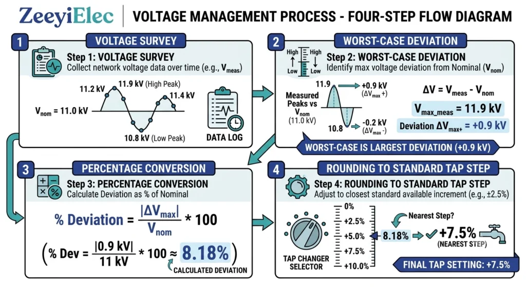
Schritt 1 – Erfassung von Spannungsmessdaten
Erfassen Sie die Minimal- und Maximalwerte der Primärspannung über einen repräsentativen Zeitraum. Beispiel: Nennspannung 11 kV, erfasster Schwankungsbereich zwischen 10,45 kV und 11,55 kV — a ±5% Variation.
Schritt 2 – Ermittlung der Abweichung im ungünstigsten Fall
Addieren Sie den erwarteten sekundärseitigen Spannungsabfall aufgrund der Impedanz bei Spitzenlast zur größeren primärseitigen Abweichung. Bei 4.5% Im Fall von Impedanz und Betrieb nahe der Volllast verstärkt sich dieser Abfall durch den Niederspannungszustand, da beide die Sekundärspannung in dieselbe Richtung beeinflussen.
Schritt 3 – In den erforderlichen Prozentsatz umrechnen
Erforderlicher Bereich (%) ≈ Primärspannungsabweichung (%) + Impedanzabfall im ungünstigsten Fall (%) bei Spitzenlast, separat für die Niederspannungs- und Hochspannungsbedingungen berechnet
Hier, ein 5% Niederspannungszustand sowie ein 4.5% Der Impedanzabfall deutet auf ±10% statt eines Feuerzeugs ±5% Einheit.
Schritt 4 – Auf Standardstufen abrunden
Standard-Schrittweiten — üblicherweise 2.5% — das bedeutet, dass ein berechneter Bedarf von 8,71 TP3T aufgerundet wird auf ±10% unter 2.5% Schritte statt einer nicht standardmäßigen Bruchzahl. Bei ländlichen Zuleitungsprojekten wird dieser Rundungsschritt häufig übersprungen, was den Lieferanten dazu zwingt, eine Rückfrage zur Klärung zu stellen, und den Beschaffungszyklus verlängert.Der Berechnungsablauf für den Abgriffbereich reicht von den Spannungsmessdaten über die Berechnung des Impedanzabfalls bis hin zur endgültigen, gerundeten Auswahl der Abgriffstufe.
Die technischen Daten und die Fachbegriffe für Wasserhähne sind offiziell definiert in IEC 60076-1, die allgemeine Norm für Leistungstransformatoren, die sich auf Nennleistungen, Spezifikationen für Abzweigwicklungen und Anforderungen an die Typenschildkennzeichnung bezieht.
Typische Werte nach Anwendungsszenario
Anwendungen im städtischen Bereich/für Kurzstrecken-Zubringer
Variation innerhalb von ±2,51 TP3T zu ±5% ist typisch in der Nähe eines Umspannwerks an kurzen, gut geregelten Zuleitungen. A ±5% Fenster bei einem 2.5% Dieser Schritt reicht in der Regel aus.
Anwendungen im ländlichen Raum/für lange Zuleitungen
Schwankungen von ±8% zu ±10% treten häufig am Ende langer Leitungen auf und werden durch den Impedanzabfall bei saisonalen Spitzenlasten noch verstärkt. ±10% Dies ist die übliche Grundvorgabe; einige Versorgungsunternehmen legen für Randzuleitungen breitere, individuell angepasste Fenster fest.
Industrielle und vorwiegend auf erneuerbare Energien ausgerichtete Stromversorger
Ein Rückstrom aus dezentralen Erzeugungsanlagen kann die lokale Spannung in Zeiten geringer Nachfrage über den Nennwert ansteigen lassen, während das Anlaufen von Motoren zu vorübergehenden Spannungseinbrüchen führt. ±10% ist typisch, manchmal asymmetrisch zugunsten der Hochspannungsseite gewichtet.
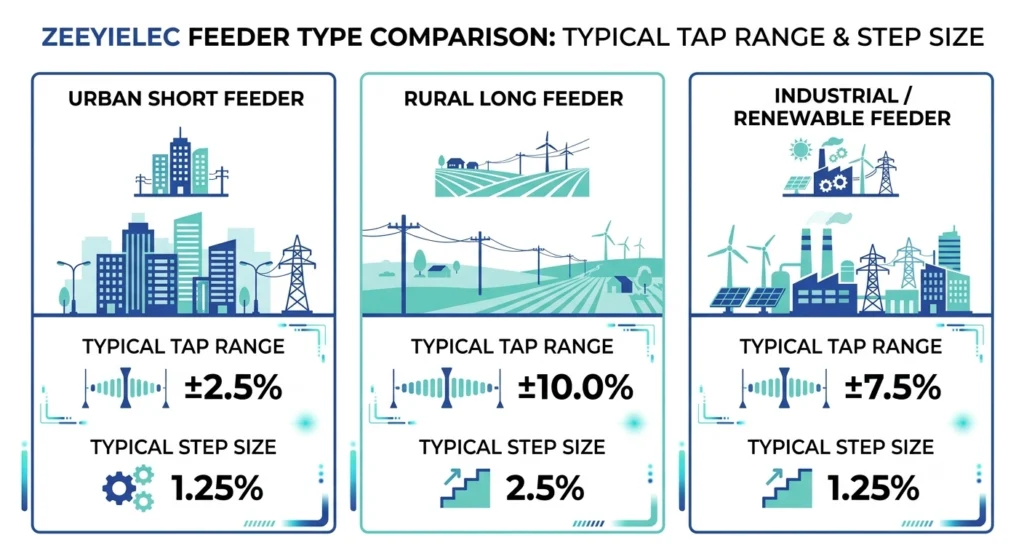
Tabelle: Typische Werte nach Szenario
Szenario
Typische primäre Variation
Gemeinsamer Bereich
Gemeinsamer Schritt
Stadtverkehr / Kurzstrecken-Zubringer
±2,51 TP3T–51 TP3T
±5%
2.5%
Ländlich / lange Zuführstrecke
±8%–10%
±10%
2.5%–5%
Industrie / mit hohem Anteil an erneuerbaren Energien
Variabel, bidirektional
±10%
2.5%
Die typischen Anforderungen an den Entnahmebereich variieren je nach Art der Einspeiseanlage – von enger gefassten städtischen Bereichen bis hin zu weiter gefassten Szenarien in ländlichen Gebieten und bei der industriellen Stromerzeugung.
Diese Bereiche gehen von einer Standardausführung des Abzweig-Stufenschalters aus; bei ungewöhnlichen Spannungsprofilen ist dennoch eine vollständige Berechnung erforderlich.
Feldbedingungen, die das Fenster verbreitern oder verengen
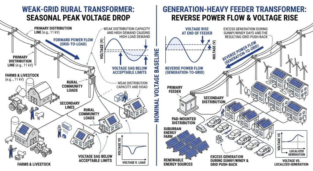
Schwache Netzabschnitte und saisonale Lastschwankungen
Ein “schwaches” Segment – hohe Quellenimpedanz im Verhältnis zur Last, häufig am anderen Ende einer langen Leitung – kann saisonale Schwankungen aufweisen, die über 10% selbst wenn der Jahresdurchschnitt eher bei 6% zu 7%. Eine Dimensionierung auf den höchsten jemals verzeichneten saisonalen Spitzenwert – und nicht auf den Jahresdurchschnitt – verhindert eine zu geringe Auslegung.
Dezentrale Energieerzeugung und Rückspeisung
Wenn die Leistung aus dezentralen Erzeugungsanlagen den lokalen Verbrauch übersteigt, fließt Strom zurück in Richtung Umspannwerk und kann die Sekundärspannung über den Nennwert ansteigen lassen – manchmal um 5% oder mehr. Damit kehrt sich die traditionelle Sichtweise auf ländliche Zuleitungen um, bei der das Risiko fast immer eher bei Niederspannung als bei Hochspannung liegt.Segmente mit schwachem Netz erweitern den Abgriffbereich aufgrund saisonaler Spannungsabfälle, während Zuleitungen mit hoher Erzeugungsleistung eine Reserve für Spannungsanstiege bei Rückstrom benötigen.
[Experteneinblick]
Bei Netzabschnitten mit geringer Netzfestigkeit ist die Dimensionierung auf den höchsten saisonalen Spitzenbedarf auszurichten, nicht auf den Jahresdurchschnitt.
Stromversorgungen mit hoher Erzeugungsleistung benötigen einen Spielraum für Spannungsanstiege, nicht nur für Spannungsabfälle
Führen Sie einen Abgleich mit den Daten einer früheren Saison durch, wenn ein einzelnes Erhebungszeitfenster unzuverlässig ist
Häufige Fehler bei der Festlegung des Anpassungsfensters
Unterdefinierung
Wenn man bei Projekten mit Verteilungstransformatoren bereits in der Planungsphase den richtigen Abgriffbereich festlegt, lassen sich zwei häufig auftretende Fehler vermeiden. Ein Projekt, das lediglich auf einen 5% Hauptschwung ohne den zusätzlichen 3% zu 5% Ein typischer Rückgang tritt häufig in einem Zeitfenster auf, das für den Spitzenbedarf zu eng ist – und die Absperrpositionen lassen sich nach der Fertigung nicht mehr korrigieren.
Überspezifizierung
Eine weniger auffällige Variante dieses Fehlers besteht darin, einen “Standardwert” aus einem früheren Projekt zu übernehmen, ohne die Berechnung für den neuen Standort erneut durchzuführen – zwei Zuleitungen mit derselben Nennspannung können sehr unterschiedliche Schwankungsprofile aufweisen. Der Abgriffbereich und die Notation des Abgriffkoeffizienten sind in Abschnitt 5 der Norm IEC 60076-1 formal definiert, während die Methode zur Umrechnung von Lastfällen und Betriebsspannungsschwankungen in einen bestimmten Abgriffbereich in der Norm IEC 60076-8 behandelt wird; keine der beiden Normen schreibt einen universell “richtigen” Bereich vor, daher sollten die Werte aus einem früheren Projekt vor der Wiederverwendung stets anhand der aktuellen Standortdaten erneut überprüft werden.
Die richtige Spezifikation in Ihrer Angebotsanfrage
Eine gut strukturierte Position in einer Angebotsanfrage sollte den berechneten Betrag enthalten (zum Beispiel, ±10%), der bevorzugte Schritt (üblicherweise 2.5%) sowie die zugrunde liegenden Daten – Nenn-Primärspannung, erfasste Schwankungen und Impedanz –, damit das Ingenieurteam des Lieferanten etwaige Unstimmigkeiten noch vor Beginn der Fertigung erkennen kann.
Der Standortkontext ist ebenso wichtig wie die Zahlen: Beachten Sie, ob die Anlage an einem schwachen Netzabschnitt liegt, saisonalen Schwankungen unterliegt oder an dezentrale Erzeugungsanlagen angeschlossen ist, da dies Anhaltspunkte für Anpassungen liefert, die eine bloße Prozentzahl nicht vermitteln würde. Bei Projekten, die mehrere Anschlussgruppen umfassen, sollten diese Daten zusammen mit der Spannungsklasse der Durchführungen, dem BIL und den Parametern zur Sicherungsabstimmung angegeben und nicht separat eingereicht werden. Projekte, in denen auch kabelseitige Komponenten spezifiziert werden, können auf Das Sortiment an Kabelzubehör von ZeeyiElec als Leitfaden für die parallele Auswahl im Rahmen desselben Ausschreibungszyklus.
Das Ingenieurteam von ZeeyiElec prüft diese Berechnungen im Rahmen der standardmäßigen Bearbeitung von Angebotsanfragen für Spezifikationen von außerhalb des Stromkreises liegenden Stufenschaltern. Eine vollständige Anleitung zu den Parametern finden Sie unter Checkliste für Angebotsanfragen zu Transformatorzubehör von ZeeyiElec.
Häufig gestellte Fragen
Wie sieht ein typischer Abgriffbereich bei Projekten mit Verteiltransformatoren aus?
Die meisten Verteilungstransformatoren nutzen einen Bereich zwischen ±5% und ±10% der Nennspannung, abhängig von den Schwankungen der Primärspannung und der Impedanz am jeweiligen Standort. Bei einer stabilen Versorgung über kurze Leitungen tendiert man zum engeren Bereich; lange ländliche Zuleitungen erfordern in der Regel den breiteren Bereich.
Wie viele Schaltstufen hat ein handelsüblicher Off-Circuit-Stufenschalter?
Standardkonfigurationen bieten in der Regel fünf Positionen, wobei die Anzahl von der Kombination aus Gesamtbereich und gewählter Schrittweite abhängt. Ein ±5%-Fenster mit einer Schrittweite von 2,5% und ein ±10%-Fenster mit einer Schrittweite von 5% ergeben in der Regel jeweils fünf Positionen mit unterschiedlichen Spannungsinkrementen.
Kann der Anzapfbereich nach der Herstellung eines Transformators noch geändert werden?
Nein – die Entnahmestellen werden bereits bei der Wicklung festgelegt, sodass ein zu kleines oder zu großes Fenster vor Ort nicht korrigiert werden kann, ohne das Gerät neu zu wickeln oder auszutauschen. Aus diesem Grund muss die Berechnung vor der Auftragserteilung genau durchgeführt werden.
Hat der Anzapfbereich Auswirkungen auf die Impedanz oder die Verluste des Transformators?
Die Nennimpedanz wird dadurch zwar nicht direkt verändert, doch ein breiterer Einstellbereich mit mehr Positionen kann zu geringen Schwankungen der Impedanz zwischen den einzelnen Einstellungen führen. Bei Standardgeräten der Verteilungsklasse sind diese Schwankungen in der Regel gering, sollten jedoch bei strengen Regelungsanforderungen mit dem Lieferanten abgeklärt werden.
Wie wirkt sich das Lastprofil auf den erforderlichen Schaltbereich aus?
Eine Einspeiseanlage mit starken Schwankungen zwischen Leerlauf und Spitzenlast verstärkt die Schwankungen auf der Primärseite durch einen Impedanzabfall, wodurch das erforderliche Fenster größer ausfällt, als es die Schwankungen auf der Primärseite allein vermuten lassen würden. Stabile, vorhersehbare Lastverläufe ermöglichen in der Regel ein engeres Fenster als der industrielle oder saisonale landwirtschaftliche Bedarf.
Was passiert, wenn der Abgriffbereich für die örtlichen Spannungsbedingungen zu eng ist?
Die Sekundärspannung liegt unter den ungünstigsten Bedingungen außerhalb der zulässigen Regelungsgrenzen, ohne dass eine Möglichkeit zur Kompensation besteht. Eine Korrektur bedeutet in der Regel, dass ein Betrieb außerhalb der Toleranz bis zum nächsten Transformatoraustausch in Kauf genommen werden muss.
Ist der Spannungsbereich dasselbe wie die Spannungsregelung?
Nein – hierbei handelt es sich um eine feste, manuell gewählte Korrektur, die bei der Inbetriebnahme oder während geplanter Abschaltungen eingestellt wird, während sich der Begriff „Spannungsregelung“ in der Regel auf die dynamische, lastabhängige Steuerung von Laststufenschaltern bezieht, die bei Leistungstransformatoren zum Einsatz kommen. Off-Circuit-Einheiten nutzen den festen Regelbereich, um bekannte, relativ stabile Zustände zu korrigieren, anstatt auf momentane Schwankungen zu reagieren.
Yo-Yo-Shi
Yoyo Shi schreibt für ZeeyiElec und konzentriert sich dabei auf Mittelspannungszubehör, Transformatorenkomponenten und Kabelzubehörlösungen. Ihre Artikel behandeln Produktanwendungen, technische Grundlagen und Einblicke in die Beschaffung für Einkäufer der globalen Elektroindustrie.





 English
 한국어
한국어 العربية
 Español
 हिन्दी
 தமிழ்
தமிழ் Deutsch (Sie)
 Français
 Português do Brasil
 Русский