Replacing a bushing well or insert on an in-service legacy transformer is one of the highest-leverage, lowest-glamour jobs in distribution maintenance. The interface is small, but it carries both the dielectric path and the environmental seal at the tank wall — and it fails more often than the windings it serves. This checklist walks the retrofit end to end: what changes, how to judge feasibility, how to verify compatibility before ordering, how to execute and test, and where retrofits go wrong.
What a Bushing Well Retrofit Actually Changes on a Legacy Transformer
A bushing well retrofit replaces the insulated interface connecting a transformer’s internal circuit to its external separable connectors — without rebuilding the transformer. On legacy oil-filled units this interface is often the reliability bottleneck, so knowing which parts a retrofit touches is the precondition for every step below.
What a retrofit replaces versus retains
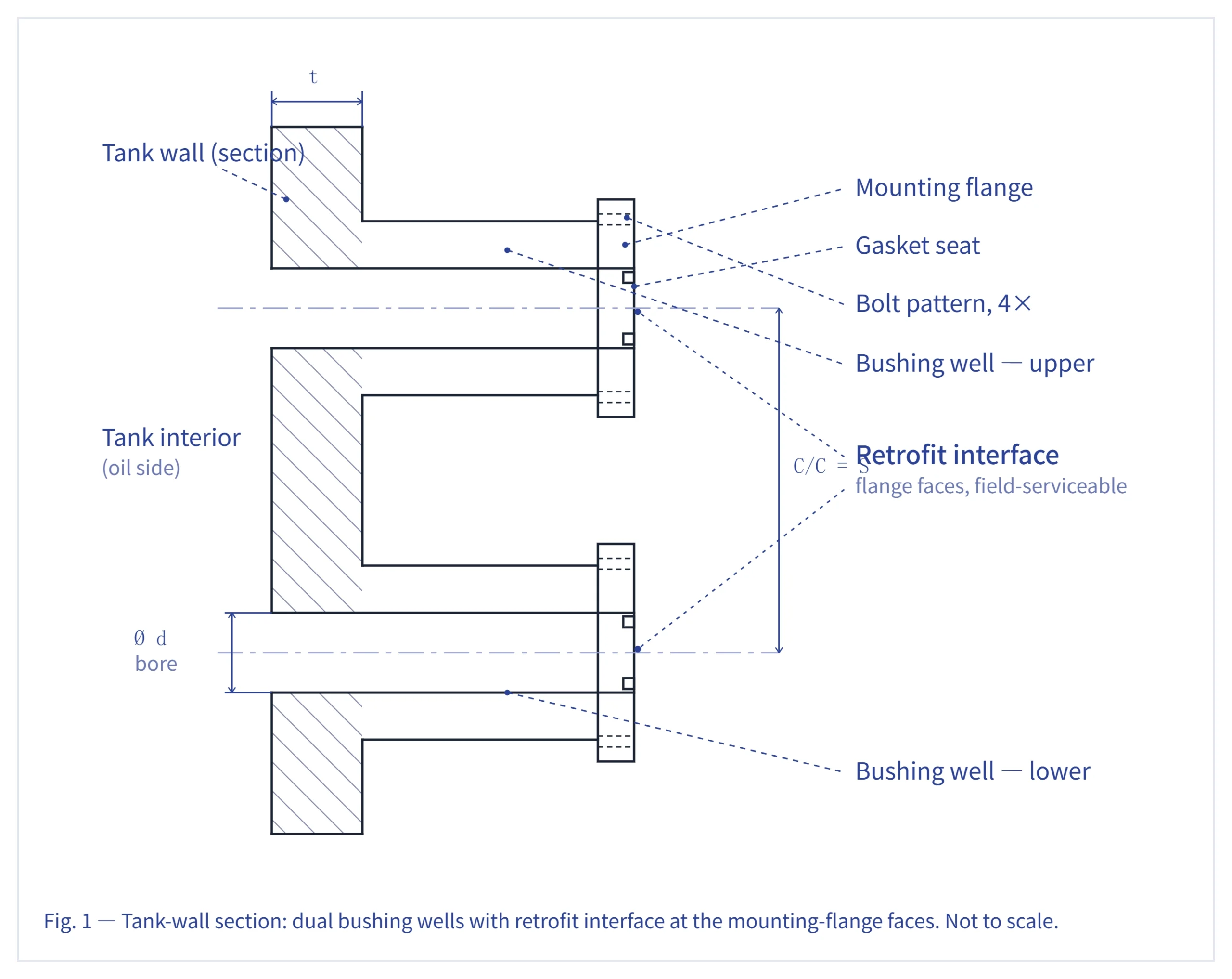
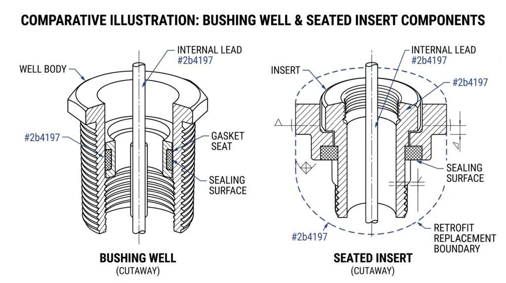
The fixed well body — bonded or bolted to the tank wall — defines the interface geometry and the 200 A continuous-current class typical of distribution wells. A retrofit may replace the well, the seated insert, or both, while retaining the tank, internal lead, and mounting flange. Crews most often replace the insert and gasket set on a sound well body; full well replacement is reserved for cracked epoxy, surface tracking, or a non-standard interface that won’t accept modern inserts.
The insert is the serviceable element seated into the well, rated to the same class — commonly 15/25 kV or 15/25/35 kV. Matching it to the well’s interface standard, not just the voltage number, is what prevents partial seating.
Why the sealing interface defines reliability
The well’s sealing surface does double duty: dielectric integrity and moisture exclusion from the oil. Legacy wells tend to fail here rather than in the bulk insulation, making a retrofit as much a sealing operation as an electrical one. Whatever the class, the assembly’s BIL must be preserved end to end — a degraded seat or mismatched insert erodes it long before an outage makes it visible. For the product-side scope, see ZeeyiElec’s bushing well and insert series.
Cutaway of a tank-wall bushing well and seated insert, identifying the well body, sealing surface, insert, internal lead, and the boundary a retrofit replaces versus retains.
Pre-Retrofit Field Assessment: Is the Legacy Well Retrofittable?
A field assessment decides whether the existing interface can host a modern well or insert, or whether the unit needs tank work first. It prevents the most expensive failure mode: a crew on site with parts that cannot be seated.
Tank-wall and mounting-flange condition
Inspect the flange face and surrounding tank wall for corrosion, pitting, weld cracking, and prior gasket damage. On one legacy 15/25 kV pad-mount unit, the wells tested sound, but flange-face corrosion under the gasket seat meant no new gasket would seal — turning a “simple insert swap” into a flange-repair job first. Flag any flatness defect; even a fraction of a millimetre of distortion breaks the moisture seal.
Existing interface identification
Record the bolt pattern, thread or clamp type, well-cavity dimensions, and the 200 A interface class. Legacy stock often mixes interface generations across one fleet, so identify each position individually rather than by transformer model.
Oil level, moisture, and contamination indicators
Assess the oil before opening it. Note oil level, visible contamination, and recent dissolved-moisture results: in-service distribution oil trending above roughly 25–30 ppm is a common signal that seals are already compromised. Please see the standard as IEEE SA – IEEE C57.106-2015. Plan any opening to minimise atmospheric exposure, especially in humid conditions. For how accessories age together across a unit, see ZeeyiElec’s transformer accessories overview.
[Expert Insight] Capturing a legacy interface with no records
Photograph the cavity, sealing surface, and bolt pattern straight-on, with a scale reference in frame.
Measure cavity depth and sealing-surface diameter directly; don’t infer them from the nameplate.
Treat each position as unique — fleets built over decades mix interface generations.
Log oil level and any moisture or DGA history before opening.
Compatibility failures are interface failures, not voltage failures. A part can carry the correct kV rating and still refuse to seat — or seat and partially discharge — if the interface standard or seating geometry doesn’t match.
Voltage class and BIL match
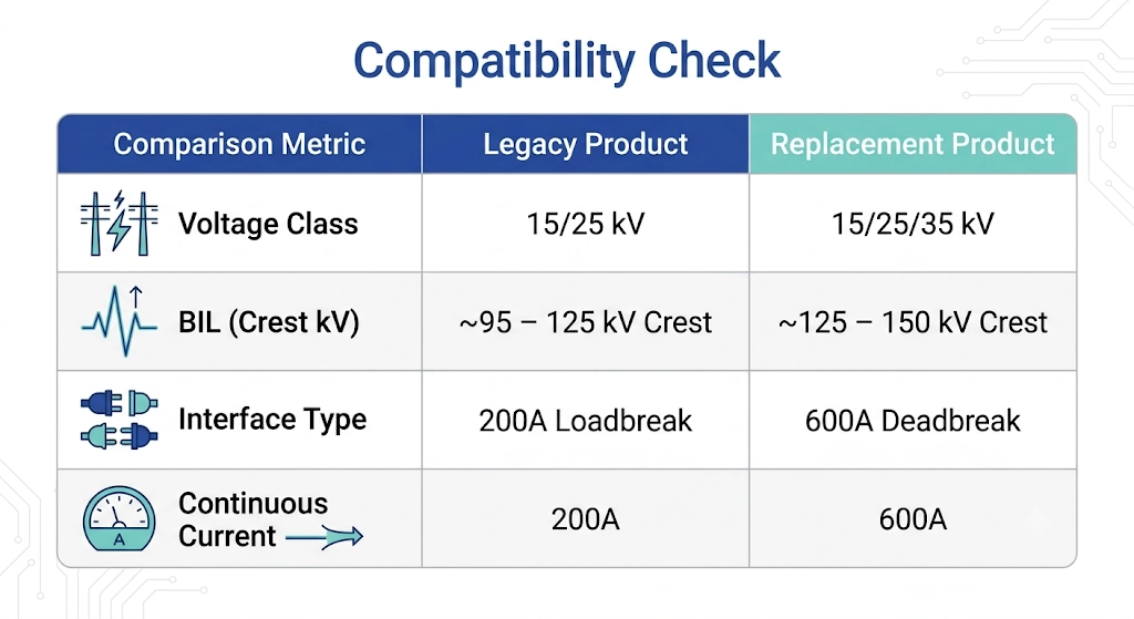
Confirm both the system voltage class and the basic insulation level. Legacy wells commonly sit in the 15/25 kV and 15/25/35 kV classes, with BIL in the order of 95–150 kV crest depending on class. An insert rated to a higher class may seat physically but is no substitute for verifying the well’s BIL still governs the assembly.
Continuous current and interface standard
Match the continuous current rating and, critically, the separable-connector interface standard. Distribution wells and inserts are predominantly built to the 200 A loadbreak interface, with 600 A deadbreak interfaces on larger apparatus. These dimensions are governed by IEEE Std 386, the standard for separable insulated connector systems rated 2.5 kV through 35 kV, which defines the geometry that lets a 200 A insert from one source seat correctly in another’s well. [NEED AUTHORITY LINK SOURCE — suggested anchor: “IEEE Std 386 separable connector interface”]
Dimensional and seating compatibility
Even within one interface class, confirm cavity depth, sealing-surface diameter, and gasket geometry against the legacy part. Where records are missing, supplier verification from photos and measurements beats catalogue assumptions.
Side-by-side compatibility reference comparing the four parameters that decide whether a replacement bushing well or insert will seat correctly in a legacy interface.
Step-by-Step Bushing Well Retrofit Execution Checklist
With assessment and compatibility cleared, this is the operational core. Treat the sequence as a baseline to reconcile with the manufacturer’s instructions — torque and handling values are part-specific.
Isolation, de-energization, and lockout
De-energize and isolate the transformer; interface work is performed dead, never under load.
Apply lockout/tagout and verify zero voltage before opening.
Disconnect and label the cable-side separable connector (elbow) at each position, and inspect it — a retrofit is the natural moment to renew aged cable-side accessories. ZeeyiElec’s cable accessories range covers the elbow and termination side that re-mates to the new insert.
Old well removal and sealing-surface preparation
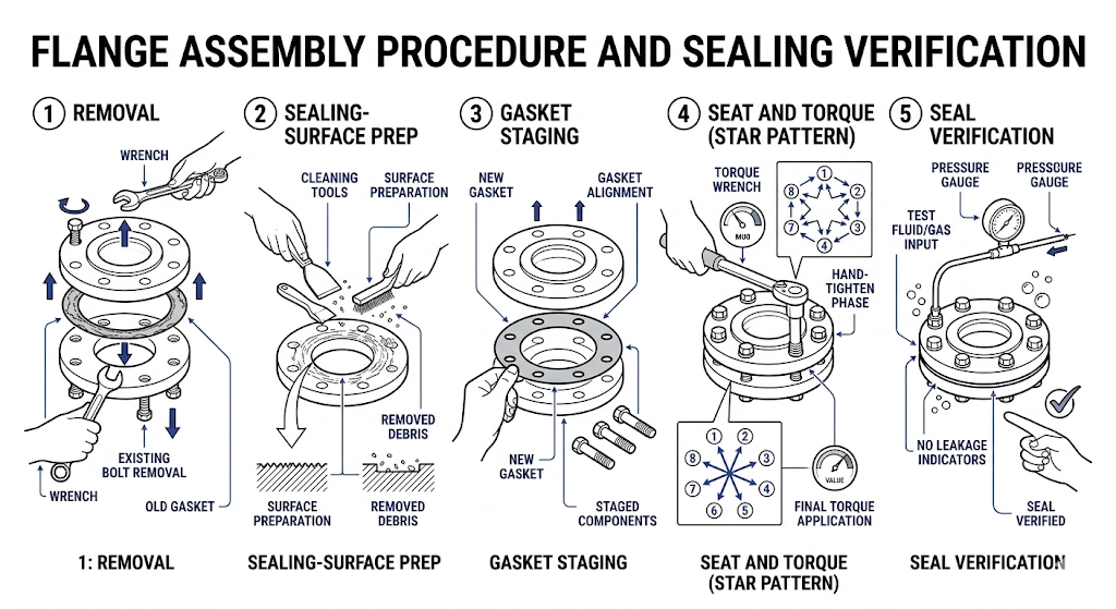
Note oil level, then remove the old insert and, if scoped, the well body, controlling oil loss and minimising the open-interface window.
Clean the sealing surface to bare, defect-free metal or epoxy; reject any seat with pitting or distortion.
Stage a new gasket dry and clean — never reuse a legacy gasket.
New well/insert installation and torque sequence
Seat the new well/insert squarely and start all fasteners by hand to avoid cross-threading.
Tighten in a cross/star pattern to the manufacturer’s value — commonly in the order of 40–70 N·m for distribution well hardware, verified against the datasheet rather than assumed.
Confirm full insert seating and gasket compression; a partially seated 200 A insert is the most common source of post-retrofit partial discharge.
Re-mate the cable-side elbow only after seating is confirmed.
Field note: on multi-position units, fully retrofitting and torque-verifying one position before opening the next limits atmospheric exposure — worth the discipline on humid days, when an open interface re-absorbs moisture within minutes.
The five-step retrofit execution sequence, from old-insert removal and surface preparation through star-pattern torque and final seal verification.
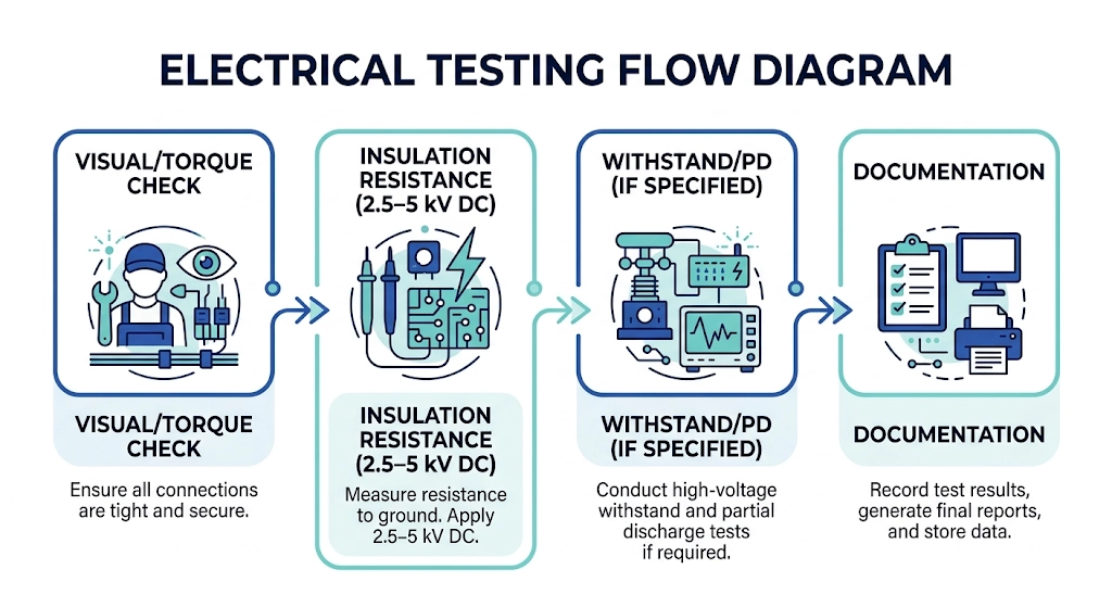
A retrofit is complete when test data confirms the interface is sound before energization, not when the insert is seated. Treat the thresholds below as starting points; governing pass criteria come from the project specification and the applicable test standard.
Visual and torque re-verification
Re-inspect every position after the assembly settles. Confirm the star-pattern torque has held, the gasket line is even, and no sealing surface is proud or pinched. A second torque check after a short settling period catches the relaxation that bedding-in gaskets show.
Insulation resistance and dielectric checks
Insulation resistance is the first electrical screen, applied at a DC test voltage matched to the class and read after a stabilisation interval.
For medium-voltage distribution interfaces, insulation-resistance tests are commonly applied at 2.5–5 kV DC, with healthy readings frequently in the order of several GΩ; a marked drop versus sister positions matters more than any single absolute value. Where the specification calls for it, an AC withstand or partial-discharge check follows, with PD ideally at or below a few pC — exact acceptance limits depend on the governing standard and should be confirmed per project.
A reading that trends low, or PD that climbs with applied voltage, points to a seating or contamination issue rather than the bulk insulation — re-seat before re-testing.
Documentation and as-left record
Capture the as-left state: torque values, test voltages, IR and PD readings, oil notes, and photos per position — supporting warranty, future diagnosis, and fleet trending.
[Expert Insight] Reading commissioning results in context
Compare each position against its siblings on the same transformer, not a fixed pass number.
A low-but-stable IR with clean PD often beats a high IR that drifts under sustained voltage.
Re-seat, then re-test — don’t average out a single bad reading.
File raw readings, not just pass/fail, so the next crew can trend them.
The commissioning verification flow run before energization, sequencing visual and torque re-checks, insulation resistance, optional withstand/PD testing, and as-left documentation.
Common Retrofit Pitfalls & Field Lessons
Most retrofit failures repeat: the same execution shortcuts produce the same delayed failures, so building each fix into the checklist as a positive action breaks the cycle.
Why most retrofit failures are delayed, not immediate
Interface failures are defined by latency. A marginal seat or pinched gasket passes commissioning, then degrades as thermal cycling and moisture work on it. On one legacy 15/25 kV unit, a retrofit that tested clean developed moisture ingress roughly four months later; the cause was a gasket seated unevenly on a surface never fully cleaned of old compound. The fix wasn’t a better insert — it was cleaning and seating discipline that should have been applied first.
Clean to bare defect-free surface; verify even gasket line
Post-retrofit partial discharge
Partially seated 200 A insert
Confirm full seating before re-mating the elbow
Torque relaxation
No settling re-check
Re-torque after a short bedding-in interval
Interface won’t seat
Interface-class mismatch
Verify separable-connector class before ordering
Premature oil degradation
Excess open-interface exposure
Work one position at a time in humid conditions
The recurring root cause
Contamination and seating discipline dominate these modes. In-service oil drifting above roughly 25–30 ppm moisture after a retrofit is rarely the insert’s fault and almost always the seal’s — which is why the sealing surface, not the part number, deserves the most field attention. Treat any single low IR reading or rising PD trend as a prompt to re-seat, not to energize and hope.
Sourcing Compatible Bushing Wells & Inserts for Legacy Fleets
Because legacy interfaces vary position by position, a supplier matches parts from specifics, not from a transformer model number — so send the data block below up front and most compatibility back-and-forth disappears.
What to send your supplier
Voltage class and BIL (e.g., 15/25 kV or 15/25/35 kV; BIL ~95–150 kV crest)
Continuous current and interface class (typically 200 A loadbreak)
Cavity dimensions, sealing-surface diameter, and bolt pattern
Photos of the existing well, insert, and seating surface per position
Quantity per position and any mixed interfaces across the fleet
ZeeyiElec’s transformer accessories RFQ checklist extends this specifics-first logic to bushings, fuses, and switches when a retrofit is bundled with other work. For legacy fleets, the team can verify interfaces from your photos and measurements before quoting, so parts arrive ready to seat rather than ready to return.
Frequently Asked Questions
Can any legacy transformer accept a bushing well retrofit?
Most can, but feasibility depends on tank-wall and flange condition plus a matchable interface; a minority of units with corroded seats or non-standard interfaces need flange or tank work first, so feasibility is decided per position rather than per fleet.
What voltage classes do bushing wells and inserts usually cover?
Distribution wells and inserts typically span the 15/25 kV and 15/25/35 kV classes at a 200 A interface, though the correct class is set by the host transformer’s system voltage and BIL and should be confirmed for each unit.
How long does a bushing well retrofit take per phase?
Field timing commonly runs from about one hour to a few hours per phase, varying with access, sealing-surface condition, and whether oil handling is required, so schedules should allow for unit-specific variation.
Do I have to de-energize the transformer for the retrofit?
Yes in practice — interface work is done de-energized and isolated, with the exact lockout and oil-handling steps depending on the transformer design and site safety procedures.
What’s the difference between a bushing well and a bushing well insert?
The well is the fixed insulated interface mounted to the tank, while the insert is the replaceable element seated into it; a retrofit may renew one or both depending on the failure mode and what the compatibility check allows.
How do I confirm interface compatibility before ordering replacements?
Match voltage class, current rating, interface standard, and seating dimensions against the legacy part, and where records are missing, send interface photos and measurements so the supplier can verify before quoting rather than after delivery.
What testing should follow a retrofit before energizing?
Expect torque re-verification plus insulation or dielectric checks, with the specific thresholds and pass criteria set by the applicable site standard and the transformer’s voltage class rather than a universal figure.
yoyo shi
Yoyo Shi writes for ZeeyiElec, focusing on medium-voltage accessories, transformer components, and cable accessory solutions. Her articles cover product applications, technical basics, and sourcing insights for global electrical industry buyers.





 English
 한국어
한국어 العربية
 Español
 हिन्दी
 தமிழ்
தமிழ் Deutsch (Sie)
 Français
 Português do Brasil
 Русский