A Bay-O-Net operation procedure is the defined sequence a maintenance crew follows to safely remove, inspect, or replace the fuse carrier and fuse link on an oil-immersed distribution transformer without breaching the tank’s dielectric integrity. The assembly mounts through the transformer sidewall so the active fuse link hangs submerged in insulating oil, which insulates live parts from the grounded tank and quenches the arc when the link clears an overcurrent.
The Mechanical Basis for the Procedure
The name comes from the bayonet-style locking mechanism connecting the fuse carrier to the stationary housing — a quarter-turn twist-and-lock action. This lets a lineman withdraw the carrier with a hot-stick tool without draining oil or de-tanking the unit, provided the transformer is de-energized or the operation stays within the assembly’s rated hot-stick handling class. On typical 15/25 kV class assemblies, the carrier is rated to interrupt fault currents up to roughly 3,500 A symmetrical, with fuse link ratings for 25 kVA–500 kVA distribution transformers commonly falling in the 2 A–50 A range.
Why Sequence Discipline Matters
Because the link sits below oil level, pulling the carrier out of sequence — before confirming de-energization or verifying full lock disengagement — risks arc exposure as the carrier breaks the seal. Field experience shows most Bay-O-Net incidents trace to a rushed or reordered procedure, not a defective link: a skipped load-status check, a forced partial seat, or a link reinstalled outside its coordination window. Fuse mounting structures, supports, and interrupting duty for this class of expulsion-type distribution fuse fall under ANSI/IEEE C37.42, which governs distribution-class fuses, fuse cutouts, fuse disconnecting switches, fuse links, and their mounting accessories.
Locking geometry, oil-immersion role, and interrupting-capacity ceiling are the three factors every step below is built around.
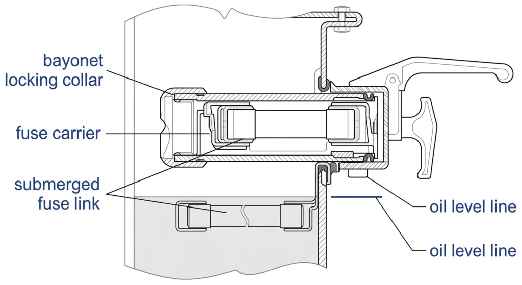
Cross-section of a Bay-O-Net fuse assembly showing the bayonet locking collar, fuse carrier, and submerged fuse link relative to oil level.
Pre-Operation Safety and PPE Requirements
Before the carrier is touched, the crew confirms load and energization status through the utility’s switching order or lockout-tagout process. A carrier withdrawn on a circuit believed de-energized but still carrying residual load can produce an arc flash the moment the bayonet lock releases.
De-Energization and Load-Status Confirmation
Crews verify zero-energy state through a documented switching sequence, not visual inspection, since carrier position gives no reliable external indication of load current. On hot-stick-only assemblies, this check also confirms the circuit falls within the carrier’s rated switching envelope — load-current interruption, not fault clearing, which remains the fuse link’s job.
Hot-Stick and Dead-Front PPE Requirements
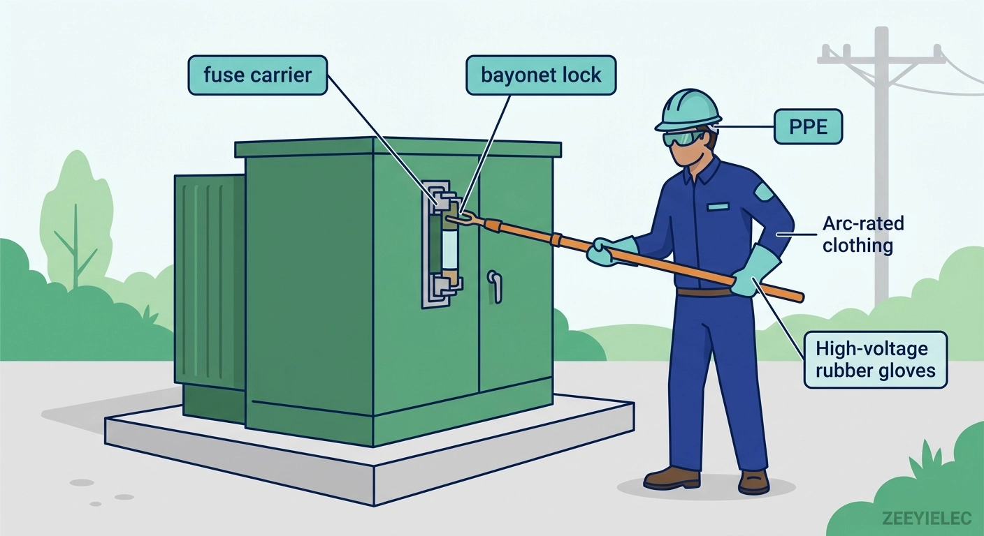
Crews use insulated hot-stick tools rated for the system voltage class (commonly 15 kV or 25 kV), paired with dielectric gloves and arc-rated clothing matched to the site’s incident energy. Dead-front dress standards apply throughout — no bare-hand contact with the housing until isolation is confirmed.
Weather and Site Condition Checks
Operating during active precipitation or high humidity risks moisture ingress the moment the carrier breaks the seal. Crews generally defer non-emergency replacements in rain or when dew point sits close to surface temperature, since trapped moisture at the reseated gasket has been linked to accelerated tracking failures.
[Expert Insight]
Skipping the documented load-status check is the most common root cause of Bay-O-Net field incidents.
An audible lock click is not proof of full engagement — feel for a positive rotational stop.
Deferring during marginal weather beats a repeat visit for a moisture-related seal failure months later.
Step-by-Step Bay-O-Net Removal and Fuse Link Replacement Procedure
With de-energization confirmed and PPE in place, the procedure follows three stages.
Removing the Fuse Carrier
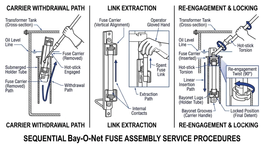
Using an insulated hot-stick, the technician engages the carrier’s pull ring and applies a controlled quarter-turn to disengage the lock. The carrier withdraws slowly and vertically — pulling at an angle can shear the sealing gasket. Withdrawal travel typically runs 300 mm–450 mm depending on carrier length; the crew holds the carrier briefly clear of the tank opening to let trapped oil drain before inspection.
Extracting and Replacing the Fuse Link
The spent link is removed from the holder tube and inspected: a clean melt at the calibrated element suggests normal overcurrent clearing, while full-length discoloration or carbonized tracking on the carrier body points to a fault current that approached the link’s interrupting rating. The replacement must match both the original current rating and the coordination point set against the backup current limiting fuse — a mismatched rating causes nuisance clearing or leaves the transformer under-protected.
Reseating and Locking the Carrier
The carrier is lowered along the same vertical path, seated fully against the flange, then rotated a quarter-turn to re-engage the lock — confirmed by a positive rotational stop, not appearance alone. A carrier that “almost” locks often looks seated but works loose under thermal cycling within weeks.
Sequential illustration of carrier withdrawal, fuse link extraction, and bayonet lock re-engagement during a Bay-O-Net maintenance operation.
Selecting the Correct Replacement Fuse Link Rating
Selecting the right rating is what actually restores protection. The link must be sized against nameplate kVA and full-load current, not simply matched to whatever was pulled from the failed carrier — that original rating may itself have been wrong.
Matching Link Rating to Transformer Capacity
Rated current is chosen to carry full-load current continuously while clearing sustained overloads and low-to-moderate faults, with margin for inrush. A link sized too close to full-load current risks nuisance clearing; one sized too high delays clearing on a genuine fault long enough to stress winding insulation.
Coordinating With the Backup Current Limiting Fuse
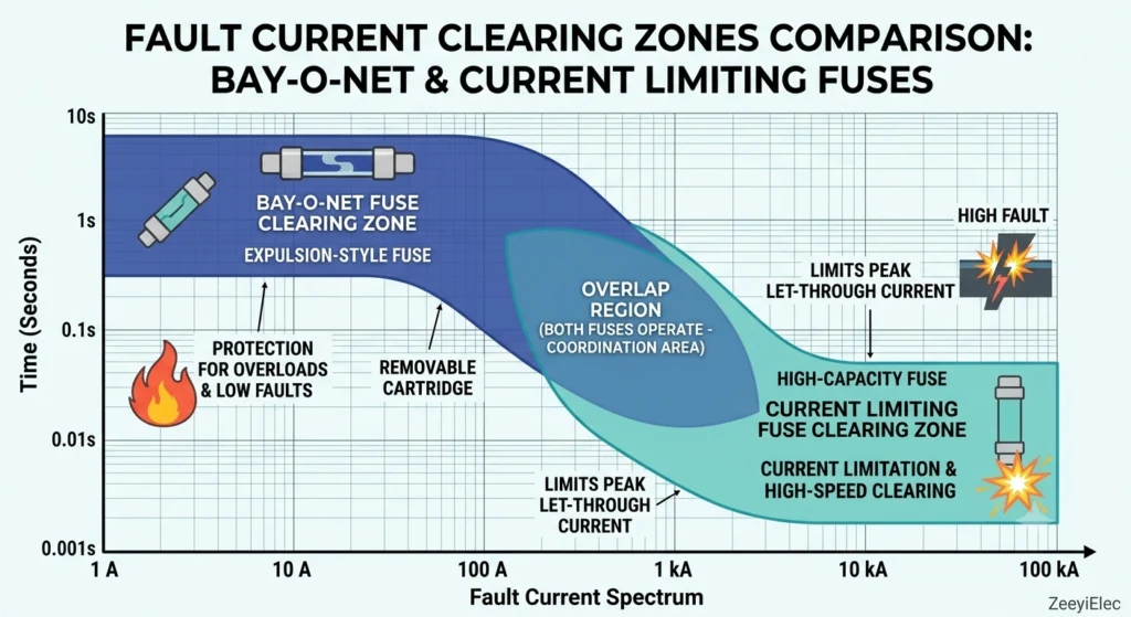
The Bay-O-Net link clears low-to-moderate faults while a backup current limiting fuse handles high-magnitude faults beyond the Bay-O-Net’s interrupting capacity. Selecting a link without checking this boundary against the current limiting fuse’s minimum melt curve can leave a gap where neither device clears reliably. Selecting a link without checking this boundary against the current limiting fuse’s minimum melt curve can leave a gap where neither device clears reliably, a coordination principle detailed in the IEEE Guide and Tutorial for the Application of High-Voltage Fuses and Accessories.
Field Verification Before Final Selection
Where the original rating is undocumented or load has changed since commissioning, crews cross-check nameplate kVA against the fuse manufacturer’s time-current coordination tables rather than trusting the carrier’s prior rating.
Coordination chart illustrating the Bay-O-Net fuse clearing zone versus the backup current limiting fuse clearing zone across the fault current spectrum.
Post-Operation Verification and Re-Energization Checks
Verification isn’t optional — treating the lock click as sufficient confirmation is a recurring cause of repeat callouts on pad-mounted units.
Visual and Torque Verification
The technician confirms the carrier sits flush against the flange with no gasket gap, and that the lock shows full rotation with no play. Where a retaining bolt is present, torque commonly falls in the 15 N·m–25 N·m range on 15/25 kV class housings, though exact values vary by design. Under-torqued hardware risks the carrier working loose; over-torqued hardware risks cracking the housing.
Oil Level and Seal Inspection
The crew confirms oil level has returned to the sight-glass reference mark and checks that the gasket shows even compression around its circumference — an uneven seal line often signals the carrier wasn’t seated squarely, which can allow slow moisture ingress even though the lock engaged correctly.
Re-Energization Sequencing
Before re-energizing, the crew confirms the replacement link’s rating matches the intended coordination point, then follows the utility’s standard switching order — closing the primary source first and monitoring for abnormal readings before applying full load. A brief post-energization load check catches marginal connections before they cause repeat clearing events.
Common Field Mistakes During Bay-O-Net Operation
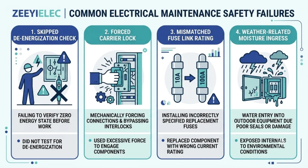
Skipping the De-Energization Verification Step
Proceeding on assumed load status rather than documented confirmation is the most consequential mistake — a carrier withdrawn under even modest residual load can produce an arc flash, since the assembly isn’t designed for load-break operation at the carrier itself.
Forcing a Partially Seated Carrier
Applying extra rotational force to a resistant carrier, rather than checking for gasket misalignment or debris, often produces a false-positive lock that loosens under normal thermal cycling.
Installing a Mismatched Fuse Link Rating
Reusing the pulled link’s rating without cross-checking nameplate kVA or the coordination window is a common error, especially where load has changed since commissioning.
Operating in Marginal Weather Without Deferring
Proceeding with non-emergency replacements during rain or high humidity accepts a moisture-ingress risk that surfaces months later as a tracking or sealing failure, hard to trace back to the service date.
Four common field mistakes during Bay-O-Net operation — skipped de-energization checks, forced carrier locks, mismatched fuse ratings, and weather-related moisture ingress.
[Expert Insight]
Two or more clearing events on the same transformer within a short window is a stronger diagnostic flag than any single event.
Carbonized tracking on a pulled carrier signals the fault approached the assembly’s interrupting ceiling.
Undocumented load changes since commissioning are a common hidden cause of coordination drift.
Related reading: ZeeyiElec’s field failure diagnosis workflow covers the broader troubleshooting process once a repeat fault pattern is suspected.
When to Escalate: Coordination With Backup Current Limiting Fuses
Not every abnormal Bay-O-Net event resolves with a simple link replacement.
Signs That Point to Coordination Review
A link clearing repeatedly within a short interval, or one showing carbonized tracking rather than a clean melt, signals the fault condition exceeds what a routine swap can resolve — the response shifts from “replace and re-energize” to “investigate coordination.”
What a Coordination Review Involves
It checks whether the installed link rating and the backup fuse’s minimum melt curve still align with present load profile and fault history — most relevant on transformers re-purposed or load-grown since commissioning, where a correctly rated link can drift out of its coordination window with no physical warning sign.
Escalation Threshold in Practice
As a general field guideline, two or more clearing events within a 12-month window, or a single event showing near-rated carbonization, warrants pulling coordination documentation rather than another straight swap. This isn’t a fixed industry number — site-specific protection philosophy may set a different trigger. Escalating at the right point avoids repeated under-protected re-energizations that eventually damage the winding rather than just the accessory.
Work With ZeeyiElec for Bay-O-Net Assemblies and Replacement Fuse Links
Maintenance teams need consistent nameplate-matched components across a service territory — mismatched carriers between suppliers create the exact coordination gaps this guide covers. ZeeyiElec manufactures Bay-O-Net fuse assemblies for 15/25 kV class oil-filled distribution transformers, engineered for dead-front hot-stick operation with a Basic Impulse Level (BIL) around 150 kV full-wave crest, alongside the current limiting fuses used for backup coordination on the same units.
Technical documentation covering carrier dimensions, link rating tables, and coordination reference data is available to confirm compatibility before ordering — critical when replacing carriers on transformers where original documentation is incomplete or the installed base spans several manufacturers.
ZeeyiElec supports OEM/ODM configuration and export documentation for utility and EPC maintenance programs sourcing components at volume. Our transformer accessories range covers the full protection and switching chain — bushings, tap changers, and loadbreak switches — while our cable accessories line supports the same distribution projects on the cable side.
Reach out with your transformer nameplate data and current link inventory for a technical fit review and quotation.
Frequently Asked Questions
How often should a Bay-O-Net fuse link be inspected in the field?
Routine visual inspection typically follows a transformer’s regular maintenance interval, with closer inspection warranted after any known fault event or sustained overload.
Can a Bay-O-Net fuse be operated while the transformer is still energized?
No — the assembly is designed for de-energized or controlled hot-stick switching depending on the carrier design, and operating outside its rated conditions risks arc flash and equipment damage.
What causes a Bay-O-Net fuse link to fail prematurely?
Premature failure usually traces to sustained thermal overload, an incorrect link rating for the transformer’s kVA class, or oil contamination degrading the arc-quenching medium.
How do I know if the fuse carrier is properly reseated after replacement?
Full mechanical engagement of the locking mechanism plus a flush visual fit against the housing confirms proper reseating, though exact torque or seating specs vary by manufacturer.
What PPE is required for Bay-O-Net maintenance work?
Crews typically need dielectric gloves, face shields, and arc-rated clothing matched to the site’s incident energy, with hot-stick tools used whenever any residual energization risk exists.
When should maintenance teams escalate to a current limiting fuse check instead of just replacing the link?
Escalation is warranted when fault currents approach or exceed the Bay-O-Net’s clearing range, since repeated high-magnitude fault activity points to a coordination review rather than a simple swap.
Why does weather matter when replacing a Bay-O-Net fuse link?
Rain or high humidity during the operation raises the risk of moisture entering the reseated gasket interface, which can cause a slow tracking or sealing failure months later rather than an immediate problem.
yoyo shi
Yoyo Shi writes for ZeeyiElec, focusing on medium-voltage accessories, transformer components, and cable accessory solutions. Her articles cover product applications, technical basics, and sourcing insights for global electrical industry buyers.





 English
 한국어
한국어 العربية
 Español
 हिन्दी
 தமிழ்
தமிழ் Deutsch (Sie)
 Français
 Português do Brasil
 Русский