What Is a Bay-O-Net Fuse Link? Core Definition and Construction
A Bay-O-Net fuse link is the replaceable protective element housed inside a Bay-O-Net fuse assembly, one of the primary protective devices used on oil-filled distribution transformers. The link, not the outer carrier or housing, is the component that actually interrupts overcurrent — it contains the calibrated fuse element that melts and clears the circuit when current exceeds its rated threshold for a sustained period. On a typical distribution transformer sized between 25 kVA and 500 kVA, link ratings commonly fall in a range of 2A to 50A, selected against the transformer’s full-load secondary current rather than assigned by a fixed rule of thumb.
Where the Link Sits in the Bay-O-Net Assembly
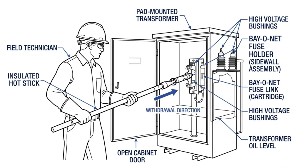
The assembly mounts through the transformer sidewall, submerging the fuse element in the unit’s dielectric oil. The link is the field-replaceable portion — a slender cartridge that a lineworker withdraws and reinserts using a hot stick, without draining oil or de-tanking the transformer. This draw-out design is what makes Bay-O-Net protection practical for utility maintenance: a blown link can be swapped in the field in minutes, provided the correct replacement rating is on hand.
Core Construction Elements
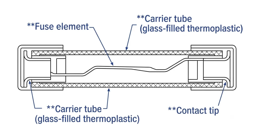
Three components define link performance. The fuse element — typically a silver or tin-alloy wire or ribbon — is calibrated to melt at a specific current-time relationship; its cross-section and alloy composition set the current rating. The carrier tube, usually glass-filled thermoplastic or fiberglass-reinforced epoxy, provides mechanical support and insulation while allowing arc byproducts to vent safely into the surrounding oil. The contact tip at the base makes the electrical connection into the transformer’s internal circuit when the link is seated. Field experience shows that a link’s clearing behavior depends as much on element geometry as on rated amperage — two links with the same current rating from different manufacturers won’t necessarily share an identical time-current curve, which matters when coordinating with a backup current limiting fuse downstream. Element melting-time tolerance is typically defined in the manufacturer’s type test report rather than a single universal standard, so cross-brand substitution should be verified against actual test data rather than assumed from current rating alone.
Cross-sectional view of a Bay-O-Net fuse link, showing the fuse element, carrier tube, and contact tip that determine clearing performance.For broader context on how this fits within the transformer’s protection scheme, see ZeeyiElec’s Bay-O-Net fuse assembly product series within the transformer accessories product line.
Expert Insight
Two links with matching amperage but different manufacturers can still clear at different speeds — always compare published time-current curves, not just the rated number.
Carrier tube material (thermoplastic vs. fiberglass epoxy) affects venting behavior during clearing; check compatibility with the assembly housing before substituting a replacement link.
Bay-O-Net Fuse Link Types: Construction and Clearing Characteristics
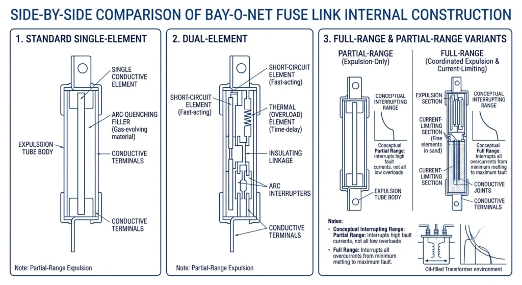
Bay-O-Net fuse links split into distinct types based on clearing speed and fault-current range, and selecting the wrong type is a common source of nuisance outages or delayed fault clearing. The three functional categories that matter most for practical selection are fast-clearing standard links, dual-element (slow-blow) links, and full-range versus partial-range designs.
Standard (Fast-Clearing) Expulsion Links
Standard links use a single-element fuse wire calibrated for a relatively steep time-current curve — they clear quickly once current exceeds rated value, typically interrupting moderate overloads and low-magnitude faults within a fraction of a second to a few seconds, depending on the multiple of rated current involved. This type suits transformers with stable, predictable loading where transient inrush is modest and the priority is fast isolation of developing faults before thermal damage accumulates in the winding.
Dual-Element / Slow-Blow Links
Dual-element links combine a fast-clearing overload section with a thermal or eutectic-alloy section that tolerates brief high-current transients without operating. This construction lets the link ride through transformer magnetizing inrush — which can reach 8 to 12 times rated current for the first few cycles at energization — without nuisance clearing, while still responding to sustained overloads or true fault conditions. Field data from repeated energization cycling shows dual-element links reduce false trips on transformers serving motor-heavy or intermittently switched loads compared to standard single-element links of the same amperage.
Full-Range vs. Partial-Range Links
Full-range links are rated to interrupt the entire fault-current spectrum independently, from low overloads up to the transformer’s maximum available fault current. Partial-range links, by contrast, are only rated to clear low-to-moderate faults — typically up to roughly 3,500A symmetrical, though the exact boundary is manufacturer- and design-specific rather than fixed by a single standard — and rely on a coordinated backup current limiting fuse to handle anything above that threshold. Specifying a partial-range link without confirming a properly coordinated backup fuse is one of the more consequential selection errors, since it can leave a gap in protection at high fault magnitudes; the actual interrupting boundary should always be confirmed against the specific manufacturer’s datasheet rather than assumed from a general figure.
Side-by-side internal construction comparison of standard, dual-element, and full-range versus partial-range Bay-O-Net fuse link types.Related reading: ZeeyiElec’s Bay-O-Net Fuse vs Current Limiting Fuse: Coordination Explained covers how partial-range links pair with backup protection.
Matching Link Current Rating to Transformer Load
Selecting a Bay-O-Net link’s current rating starts with the transformer’s full-load ampacity, not the link amperage listed on a previous unit’s nameplate or a generic catalog default. Getting this step wrong is one of the more frequent causes of either nuisance clearing under normal load swings or, worse, a link that never operates in time to protect the winding.
Reading Transformer Nameplate kVA into Link Amperage
Full-load current on the primary side is calculated from the transformer’s kVA rating and primary voltage, then the link is sized above that value with margin for normal load variation. For a typical 500 kVA, 12.47 kV single-phase distribution transformer, primary full-load current lands in a range that generally calls for a link rated in the 40A to 65A class, though the exact figure depends on connection type and utility-specific sizing tables. A link sized too close to full-load current will operate on ordinary seasonal load growth or temperature-driven demand shifts; one sized too high delays fault clearing and increases thermal stress on the winding during an actual fault.
Inrush and Overload Margin Considerations
Beyond steady-state load, the link must survive transformer energization inrush without operating. Magnetizing inrush current can reach several multiples of rated current for the first several cycles after switching in, which is why dual-element links are frequently specified on transformers subject to frequent switching or backup restoration duty. A margin of roughly 25% to 50% above calculated full-load current is a common starting point for standard links, though this should be checked against the manufacturer’s specific time-current curve rather than applied as a fixed rule. Capturing this loading data at the RFQ stage — rather than after a nuisance-trip complaint — is what keeps link rating from being left to guesswork.
Coordinating Bay-O-Net Links with Backup Current Limiting Fuses
Bay-O-Net links rarely operate as a standalone protection scheme on modern distribution transformers — most installations pair a partial-range link with a series-connected backup current limiting fuse, and the coordination between the two determines whether the transformer is actually protected across its full fault-current spectrum, not just on paper.
Clearing Zone Boundaries Between the Two Devices
The Bay-O-Net link is calibrated to handle low-to-moderate overloads and secondary faults, generally up to a few thousand amperes symmetrical, while the current limiting fuse takes over for high-magnitude primary faults that can reach tens of thousands of amperes within a half-cycle. The two devices must have overlapping time-current characteristics at the boundary between their operating zones — a gap here means neither device clears a fault that falls in the unprotected band.
For a fault current If falling between the link’s maximum interrupting rating and the current limiting fuse’s minimum melting threshold, coordination is verified when the link’s total clearing time Tlink at If remains shorter than the current limiting fuse’s minimum melting time TCLF(min) across the full overlap band — expressed as Tlink(If) < TCLF(min)(If) for all If in the shared range.
Common Coordination Errors That Void Protection
The most frequent field error is specifying a link and backup fuse from different manufacturers’ families without cross-checking published time-current curves, since two “equivalent” ratings from different vendors don’t always share the same melting characteristic. A second common mistake is upsizing the link after a nuisance-trip complaint without re-verifying that the new link rating still coordinates with the existing backup fuse — this can silently widen the unprotected current band. Coordination studies referencing manufacturer time-current curve data, cross-checked against IEC 60282-1 requirements for high-voltage fuse performance, remain the most reliable way to confirm a link and backup fuse pair actually protect the full fault spectrum rather than assuming compatibility from current rating alone.
Expert Insight
Never assume rating equivalence across brands — pull both devices’ time-current curves and check the overlap band before finalizing a link/backup fuse pair.
After any link upsizing to address nuisance trips, re-verify coordination with the existing backup fuse; the fix for one problem can quietly create another.
Field Selection Mistakes and Practical Case Notes
Selection errors on Bay-O-Net links rarely show up on a datasheet review — they surface months later as nuisance trips, delayed fault clearing, or a service call that traces back to a rating decision made without full loading data.
Mistake 1: Rating Selected from Nameplate Alone
A transformer’s nameplate provides kVA and voltage ratio, but not the actual demand profile the unit will see in service. Crews sometimes size the link directly off nameplate full-load current without accounting for site-specific loading — a transformer serving a feeder with heavy motor starting or seasonal peak demand needs different margin than one on a steady residential load. Relying on the nameplate alone tends to produce a link that’s technically correct in isolation but mismatched to actual field conditions.
Mistake 2: Ignoring Ambient/Loading Derating
Link clearing characteristics shift with ambient temperature and prior loading history. A link operating in an enclosure or pad-mount cabinet running consistently warmer than open-air conditions — commonly 10°C to 20°C above ambient in poorly ventilated installations — will clear at a lower actual current than its rated curve suggests at standard test conditions. Selection that ignores this derating effect can leave less margin than the paper rating implies.
Field Case: Nuisance Tripping from Undersized Link
On a pad-mounted 300 kVA transformer serving a commercial feeder with intermittent large-motor starting, a standard single-element link sized tight to calculated full-load current cleared repeatedly during motor inrush events, each requiring a truck roll and field replacement. Root-cause review found the link’s fast-clearing curve had no margin for the feeder’s actual inrush profile. Switching to a dual-element link one step up in rating, verified against the transformer’s magnetizing inrush duration, eliminated the nuisance clearing without compromising fault response — illustrating why loading profile, not just nameplate current, has to drive the selection decision.
Field replacement of a Bay-O-Net fuse link using an insulated hot stick, performed without draining transformer oil.
Replacing Bay-O-Net Links Safely in the Field
Bay-O-Net link replacement is designed for hot-stick, de-energized field service without draining transformer oil, but the procedure still depends on correct sequencing and post-installation verification to confirm the replacement link is seated and rated correctly.
Hot-Stick Removal Sequence
Before any physical work, the transformer circuit must be de-energized and isolated per standard switching procedures — link replacement is not a live-line operation. Once isolated, the lineworker uses an approved hot stick to engage the link’s pulling eye and withdraw it from the carrier housing in a single controlled motion, avoiding side-loading that can crack the carrier tube’s epoxy or fiberglass body. The blown link is inspected visually for the failure signature — a clean element separation typically indicates normal overcurrent operation, while carbon tracking or carrier discoloration can point to a contamination or moisture issue upstream of the fuse itself rather than a simple overload event. The replacement link is confirmed against the assembly’s nameplate rating before insertion; a link with the correct physical dimensions but wrong current rating will seat without resistance, so visual amperage confirmation is a required step, not optional.
Post-Replacement Verification Checks
After the new link is seated and the contact tip fully engages the internal circuit, field crews confirm proper seating resistance and check that the carrier assembly is fully latched before re-energizing. A common oversight is skipping a load-side voltage check after restoration, which would otherwise catch a link seated at an angle or a carrier not fully home. On installations with a coordinated backup current limiting fuse, technicians should also confirm the backup fuse was not affected by whatever event caused the original link to clear — a link operation on a high-magnitude fault can sometimes stress the backup fuse without fully clearing it, a detail easy to miss if the replacement is treated as routine maintenance rather than a fault-response event.
Bay-O-Net Link Type Selection by Application Scenario
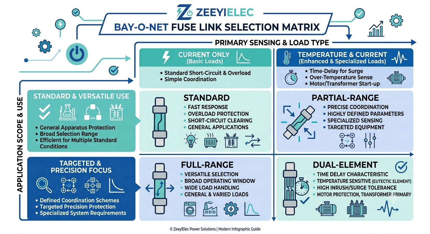
Choosing between standard, dual-element, full-range, and partial-range Bay-O-Net links comes down to matching each type’s clearing behavior to the transformer’s loading profile, switching frequency, and backup protection scheme rather than defaulting to whichever type was used on the last project.
Link Type Comparison by Application
Link Type
Best-Fit Application
Typical Current Range
Key Selection Factor
Standard (fast-clearing)
Stable, steady-load transformers with minimal switching
Commonly 2A–50A class for 25–500 kVA units
Fast response to overloads; limited inrush tolerance
Dual-element (slow-blow)
Transformers with frequent switching, motor starting, or restoration duty
Same nominal range, rated one step above equivalent standard link
Rides through inrush (often 8×–12× rated current) without nuisance clearing
Full-range
Installations without a coordinated backup current limiting fuse
Sized to clear entire available fault current independently
Must interrupt the full fault spectrum alone
Partial-range
Installations with a verified, coordinated backup current limiting fuse
Typically rated up to roughly 3,500A symmetrical
Requires confirmed coordination; unprotected gap risk if backup fuse is mismatched
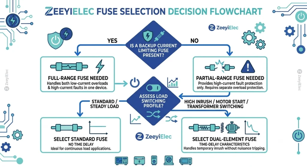
The practical decision sequence is straightforward: confirm whether a backup current limiting fuse is present and coordinated (full-range vs. partial-range), then evaluate the load’s switching and inrush profile (standard vs. dual-element). Skipping the first question and jumping straight to amperage selection is what produces the coordination gaps and nuisance-trip patterns described in the earlier field cases.
Decision flow for selecting Bay-O-Net link type based on backup fuse presence and transformer load switching profile.For system-level context on where these decisions fit within broader accessory specification, see ZeeyiElec’s complete selection map for transformer accessories.
Get the Right Bay-O-Net Fuse Link Specified for Your Project
Bay-O-Net link selection depends on transformer loading, switching behavior, and whether a coordinated backup current limiting fuse is in place — details that vary enough project to project that a generic catalog rating rarely fits without verification. Sharing the transformer’s kVA rating, voltage class, and any known switching or motor-starting characteristics allows link type and amperage to be confirmed against actual site conditions rather than assumed from nameplate data alone.
ZeeyiElec’s engineering team reviews link and backup fuse pairings against manufacturer time-current data to help confirm coordination before an order ships, reducing the chance of a rating mismatch surfacing after installation. Bay-O-Net fuse assemblies rated 15/25kV are supplied with a 150 kV BIL, and technical support can walk through link options within that family for a given loading profile.
Projects specifying transformer accessories alongside cable accessories can consolidate technical review across both product lines. Submit transformer nameplate data, site loading notes, and any existing backup fuse specifications through a project inquiry, and expect a technical response addressing link type, rating, and coordination fit within the standard response window.
Request a quote referencing your transformer’s kVA and voltage class for a rating recommendation.
Frequently Asked Questions
What is the difference between a Bay-O-Net fuse link and a full fuse assembly?
The link is the replaceable internal element, typically rated from a few amperes up to several hundred, while the assembly is the complete tank-mounted housing and carrier that holds it — only the link is swapped during routine fuse replacement, not the housing.
How do I know what current rating my Bay-O-Net fuse link needs?
Link rating is derived from the transformer’s full-load current plus an overload margin, commonly landing in a range determined by kVA and voltage class rather than a single fixed number, so the nameplate current should always be cross-checked against actual loading conditions before ordering.
Can Bay-O-Net fuse links be replaced without draining transformer oil?
Yes — the design’s hot-stick, draw-out construction allows link replacement without de-tanking or draining oil, though de-energization and standard switching procedures still apply before any hands-on work.
What’s the difference between a full-range and partial-range Bay-O-Net link?
A full-range link is intended to clear the entire fault current spectrum on its own, while a partial-range link only handles low-to-moderate faults and depends on a coordinated backup current limiting fuse for high-magnitude events.
How often should Bay-O-Net fuse links be inspected or replaced?
Inspection intervals vary by utility practice and loading history, but links are typically checked during scheduled maintenance windows or after any suspected overload event rather than on a fixed replacement calendar.
Do Bay-O-Net fuse links coordinate with current limiting fuses automatically?
No — coordination depends on selecting a link and backup fuse pair whose time-current characteristics overlap correctly at the design stage, so mismatched ratings can leave a coordination gap even though both devices are physically installed.
What happens if the wrong Bay-O-Net link rating is installed?
An undersized link causes nuisance tripping under normal load swings, while an oversized link can fail to clear a developing fault in time, allowing thermal stress to reach the transformer winding before protection operates.
yoyo shi
Yoyo Shi writes for ZeeyiElec, focusing on medium-voltage accessories, transformer components, and cable accessory solutions. Her articles cover product applications, technical basics, and sourcing insights for global electrical industry buyers.





 English
 한국어
한국어 العربية
 Español
 हिन्दी
 தமிழ்
தமிழ் Deutsch (Sie)
 Français
 Português do Brasil
 Русский