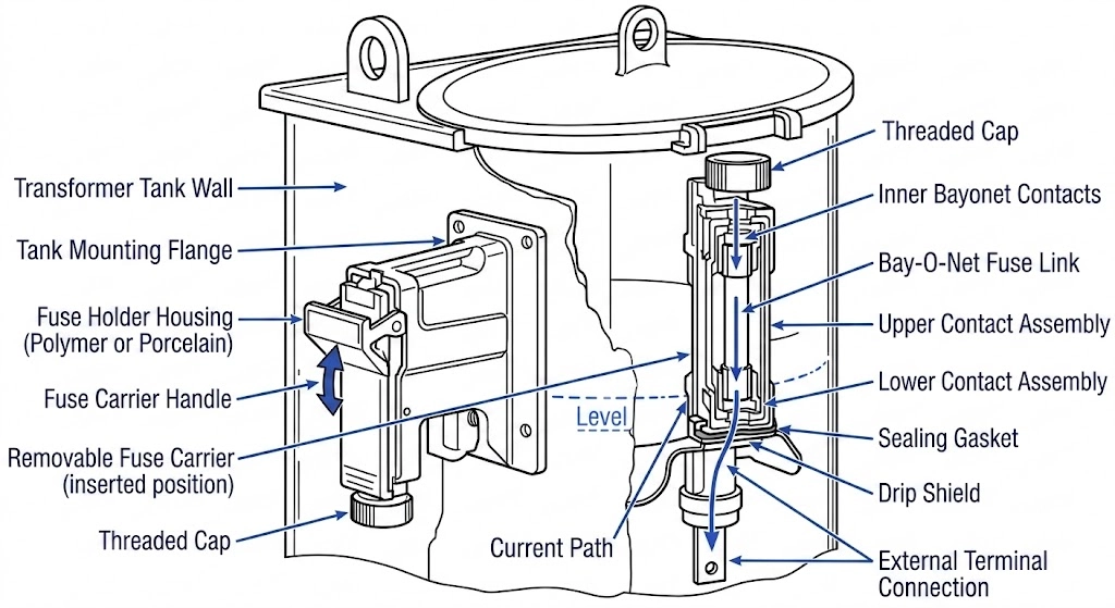
A Bay-O-Net fuse assembly is a specialized, draw-out overcurrent protection device designed explicitly for oil-filled distribution transformers. Unlike standard expulsion fuses mounted externally on utility poles, the Bay-O-Net assembly integrates directly into the transformer tank wall. This configuration submerges the active fuse link within the transformer’s dielectric fluid, leveraging the oil’s high dielectric strength and cooling properties to quench arcs generated during fault interruption.
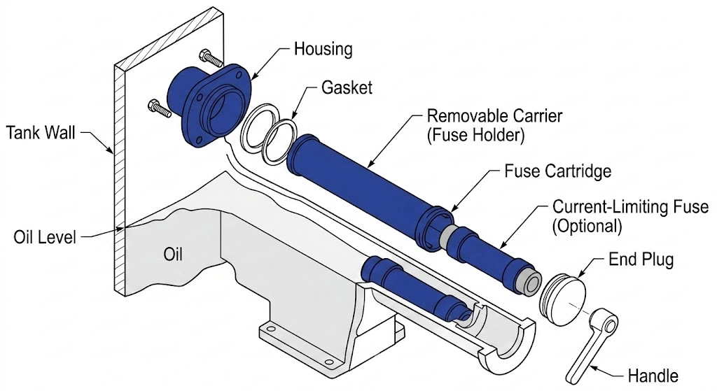
The assembly consists of two primary structural components: a stationary housing permanently mounted and sealed to the transformer tank, and a removable fuse carrier (the “holder”) that contains the replaceable fuse link cartridge. This two-part design facilitates safe, dead-front access for line crews. When a fault occurs or maintenance is required, operators can extract the fuse carrier using a hot-stick without breaching the main transformer tank seal or exposing themselves to live internal high-voltage components.
Operationally, when the internal fuse element melts due to an overcurrent event, the resulting arc rapidly vaporizes the surrounding transformer oil. This phase change creates high-pressure gas that forcibly expels the arc and conductive byproducts down and away from the fuse contacts through the open-ended cartridge tube. The surrounding cold oil immediately collapses back into the arc path, restoring dielectric strength and completing the interruption process within a half-cycle to several cycles, depending on the fault magnitude. This interaction between the fuse element and the insulating oil makes مجموعات صمامات باي-أو-نت critical components within the broader category of ملحقات المحولات, specifically engineered for the thermal and chemical realities of submerged operation.
Application Scope: Where to Specify 15/25kV Assemblies
Specifying the correct Bay-O-Net fuse housing and carrier requires matching the assembly’s dielectric and continuous current capabilities to the distribution transformer’s operational parameters. These assemblies are primarily deployed in liquid-immersed pad-mounted and pole-mounted transformers serving residential, commercial, and industrial utility loads.
Voltage Class and BIL Ratings
The primary distinction when specifying a Bay-O-Net assembly is the electrical network’s maximum operating voltage. A 15kV class assembly is typically deployed on distribution systems operating at 4.16kV, 7.2kV, 12.47kV, or 13.2kV. Conversely, a 25kV class housing is required for 14.4kV through 24.9kV systems to provide adequate strike distance and prevent flashovers along the exterior of the carrier.
Both voltage classes must closely coordinate with the transformer’s overall insulation system. In standard North American utility applications, a 15/25kV Bay-O-Net assembly is engineered to meet or exceed a 150kV Basic Impulse Insulation Level (BIL). This ensures the accessory housing can withstand the same lightning and switching surge transients as the main transformer tank bushings, adhering to the testing parameters outlined in [NEED AUTHORITY LINK SOURCE: IEEE Std C57.12.00 for liquid-immersed distribution transformers].
Transformer Capacity and Load Currents
Bay-O-Net assemblies are not universal for all transformer sizes; their application is strictly bound by continuous current-carrying limits and heat dissipation capabilities within the insulating oil.
For standard single-phase and three-phase distribution transformers, the 15/25kV Bay-O-Net assembly is generally suitable for capacities ranging from 50 kVA up to 2,500 kVA. The continuous current rating of a standard thermoplastic Bay-O-Net housing and contact assembly is typically limited to approximately 160A. If a transformer’s full-load primary current exceeds this threshold (for instance, a large 2,500 kVA unit operating at 4.16kV, which draws ≥ 340A per phase), a standard Bay-O-Net cannot be used. In such cases, engineers must specify an alternative protection scheme, such as a vacuum fault interrupter or an external substation breaker.
When selecting the assembly for a specific project, procurement teams and electrical engineers must verify that the steady-state load current, plus any utility-mandated overload margins, does not exceed the thermal limits of the fuse carrier contacts. Pushing an assembly beyond its continuous thermal rating leads to localized heating, accelerated carbonization of the oil near the tank wall, and eventual dielectric breakdown of the housing itself.
Expert Insight: 160A Continuous Limit
Never push a standard Bay-O-Net housing past its 160A continuous load rating. For a 2,500 kVA transformer operating at 12.47kV, the primary current is approximately 115A, falling well within safe operating parameters. At 4.16kV, the identical kVA draws roughly 347A, necessitating alternative external breaker configurations entirely.
Expert Insight: BIL Verification
Always verify that the housing’s BIL rating directly matches the transformer tank’s overall insulation design. Installing an under-rated assembly creates a weak point in the dielectric envelope, risking localized flashovers during severe switching transients or lightning strikes.
Fuse Link Selection: Current Sensing vs. Dual Sensing
The protective intelligence of a Bay-O-Net assembly resides entirely within its replaceable cartridge. Specifying the correct fuse link dictates whether the transformer is protected solely against electrical faults or also guarded against catastrophic thermal degradation. Engineers must select between two distinct operating mechanisms based on the installation environment and utility loading practices.
Current-Sensing Fuse Links
Current-sensing links operate on a straightforward electro-thermal principle: they melt and clear a circuit based purely on the magnitude and duration of the overcurrent passing through the element.
These links are manufactured with elements that respond strictly to the I2R heating generated by secondary system faults or equipment overloads. For example, a standard 65A current-sensing link might be designed to clear a 1,500A secondary fault within 0.05 seconds. Because the element’s baseline melting point is relatively high, the Time-Current Curve (TCC) of a pure current-sensing link remains largely unaffected by the ambient temperature of the surrounding transformer oil. They are the standard choice for pole-mounted or pad-mounted distribution units where internal thermal monitoring is handled by separate secondary breakers, or where utility operating protocols prioritize maintaining power during peak load conditions unless a hard electrical fault occurs.
Dual-Sensing Fuse Links
Dual-sensing links provide an essential secondary layer of protection by responding to both electrical overcurrents and elevated transformer oil temperatures.
In addition to a standard fault-clearing component, dual-sensing cartridges incorporate a specialized eutectic alloy designed to melt at specific fluid temperatures—typically engineered to operate when oil reaches 145°C. In field applications, severe ambient heat combined with sustained load currents can easily push top-oil temperatures past 105°C. This accelerates insulation aging and causes internal tank pressure to spike, often exceeding safe operating limits of ≥ 10 psi. Field engineers frequently specify dual-sensing links for subsurface commercial vault installations or densely packed industrial substations with poor convective airflow.
If the transformer core begins to overheat due to restricted ventilation, the surrounding hot oil will melt the eutectic element and disconnect the load before catastrophic core damage occurs, even if the steady-state current remains well below the nominal electrical fault threshold. However, this creates a specific field maintenance reality: if a line crew replaces a thermally tripped dual-sensing link without addressing the overloaded phase or the high ambient ΔT, the replacement fuse will inevitably melt again once the oil reheats.
The Two-Fuse Protection Scheme: Coordinating with Current Limiting Fuses
A Bay-O-Net fuse assembly is rarely deployed as a standalone protection device. While excellent at sensing internal thermal overloads and clearing low-magnitude secondary faults, its expulsion-style interrupting mechanism has a definitive physical limit. To achieve full-range protection, engineers specify a two-fuse coordination scheme: a Bay-O-Net fuse wired in series with a صمامات الحد من التيار.
Series Coordination Logic
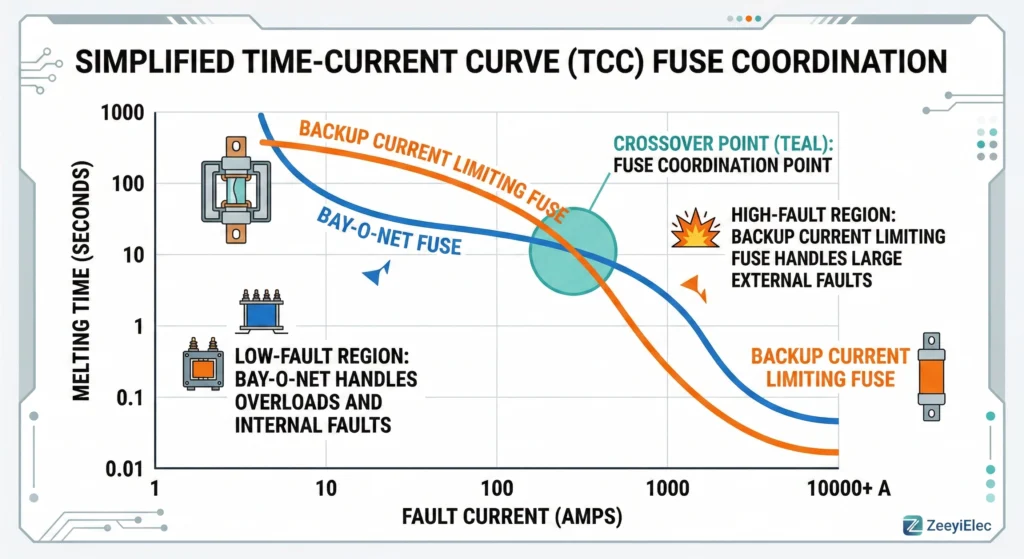
The core logic of this two-fuse approach relies on dividing the fault current spectrum. The Bay-O-Net element acts as the primary defense against typical distribution network issues—such as a secondary short circuit or a sustained overload—that generate fault currents up to approximately 3,500A. When a fault occurs in this low-current region, the Bay-O-Net link melts, expelling the arc within the oil and successfully clearing the circuit before the current limiting fuse is affected.
However, if a catastrophic primary fault occurs (e.g., a bolted short across the primary windings), the resulting fault current can instantaneously spike to tens of thousands of amperes. At these magnitudes, a Bay-O-Net assembly would rupture violently, potentially destroying the transformer tank. This is where the backup partial-range current limiting fuse takes over.
Figure 02:Proper series coordination ensures the Bay-O-Net clears low faults while the backup fuse clears high faults.
The current limiting fuse is engineered to interrupt massive faults—often rated for 50,000A symmetrical or higher—within a fraction of a half-cycle. By operating so rapidly, it limits the peak let-through current (Iالذروة) and the total I2t energy delivered to the transformer. The critical engineering task is selecting the correct ratings so their Time-Current Curves (TCC) intersect perfectly. The Bay-O-Net must clear all faults below the minimum interrupting current of the backup fuse, and the current limiting fuse must operate fast enough to protect the Bay-O-Net from massive primary faults.
Field Operations: Hot-Stick Handling and Oil Maintenance
Replacing a blown fuse link in a live environment is a standard distribution maintenance procedure, but it requires strict adherence to mechanical and physical safety protocols. Even with a dead-front transformer design, the interface between the ambient environment and the internal dielectric fluid presents operational hazards. Before interacting with the fuse assembly, line crews must confirm that the internal مفتاح كسر التحميل is completely open to isolate the load and prevent drawing a dangerous arc during extraction.
Venting Transformer Pressure
During normal operation, internal transformer fluid expands, pressurizing the sealed tank. Before unlocking the Bay-O-Net carrier, operators must manually bleed this pressure using the tank’s pressure relief valve (PRV). If a technician attempts to remove the carrier while the tank is pressurized—often operating at ≥ 8 psi under heavy load—hot dielectric fluid (frequently exceeding 90°C) will forcibly expel through the open housing outward toward the operator.
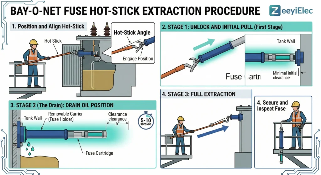
Hot-Stick Extraction Procedure
Extraction requires a standard shotgun hot-stick and a disciplined, two-stage pull. First, the operator latches the hot-stick onto the carrier’s operating eye and rotates it to unlock the mechanical seal. The carrier should be pulled outward approximately 2 to 3 inches and held in place for 5 to 10 seconds. This critical pause breaks the internal vacuum and allows the hot oil trapped inside the cartridge tube to drain back into the main tank. Once properly drained, the operator can swiftly extract the carrier at a slight upward angle to clear the housing.
Figure 03:A mandatory 5-10 second drain pause allows hot oil to clear the cartridge tube before full extraction.
Managing Oil Viscosity in Cold Environments
Ambient temperature drastically alters fluid dynamics inside the transformer tank. In extreme winter conditions where ambient temperatures drop below -20°C, the kinematic viscosity of standard mineral oil increases exponentially. This thick, syrup-like state creates substantial hydraulic drag against the submerged cartridge. If a technician yanks the carrier out too quickly in cold oil, the mechanical stress can snap the fiberglass operating rod or damage the housing’s internal contacts. Furthermore, highly viscous oil drains much slower, requiring the operator to extend the initial drain pause to ≥ 15 seconds to prevent dragging a conductive stream of fluid across the external tank components.
Expert Insight: Stuck Carrier Diagnostics
If the Bay-O-Net carrier heavily resists the initial 2-3 inch pull during extraction, do not force it with the hot-stick. Sustained overloading beyond the 160A continuous rating may have caused the internal housing contacts to micro-weld directly to the carrier base, requiring a de-energized tank inspection.
Expert Insight: Cold Weather Hydraulic Lock
Severe cold weather creates a temporary hydraulic lock inside the tight mechanical tolerances of the cartridge tube. Operators must extend the drain pause beyond the standard 5-10 second guidelines to ensure the thick, viscous oil fully clears before completing the extraction sequence.
Sourcing 15/25kV Bay-O-Net Assemblies for Your Next Project
Specifying the correct Bay-O-Net fuse assembly for your distribution transformer project requires exact alignment between the network’s electrical parameters and the component’s mechanical capabilities. Before finalizing a purchase order, procurement and engineering teams must verify three critical specifications: the primary voltage class (verifying a minimum 150kV BIL rating for 15/25kV networks), the required continuous current capacity (typically capped at 160A for standard housings), and the precise fuse link technology (current-sensing versus dual-sensing).
Mismatched components—such as installing a pure current-sensing link in a subsurface vault transformer prone to severe ambient temperature rises—can lead to catastrophic core failures that bypass standard electrical protection entirely. Furthermore, coordinating the primary transformer protection interfaces with incoming ملحقات الكابلات ensures complete structural integrity from the grid connection point right into the transformer oil.
If your current project requires technical validation of Time-Current curves, dimensional compatibility checks for tank wall mounting, or custom OEM configurations, our engineering team is available for direct consultation. Share your transformer datasheets and specific protection requirements, and we will assist in selecting the exact Bay-O-Net assemblies and coordinated backup fuses to ensure your network remains secure and compliant.
الأسئلة المتداولة
هل يمكن استبدال مصهر Bay-O-Net أثناء تنشيط المحول؟
While physically possible under certain controlled conditions, industry safety protocols strictly require de-energizing the transformer or opening the internal loadbreak switch to drop the load before extraction. Pulling a fuse carrier under load can draw a lethal arc through the oil, especially if the continuous load current exceeds 100A.
What causes a dual-sensing Bay-O-Net fuse to operate if there is no electrical fault?
Dual-sensing links feature a eutectic alloy that melts when bulk oil temperatures exceed specific safety thresholds, typically engineered around 145°C. This thermal trip usually indicates severe ambient heating, poor subsurface vault ventilation, or sustained equipment overloading rather than a distinct short circuit.
Does the transformer oil level affect Bay-O-Net operation?
Yes, if the dielectric fluid drops below the Bay-O-Net housing contacts, the fuse loses its vital arc-quenching medium and cooling capability. Operating a normally submerged fuse in the empty air space of a tank drastically reduces its interrupting rating and can lead to a catastrophic housing rupture during a ≥ 1,000A fault.
What is the difference between a 15kV and a 25kV Bay-O-Net housing?
A 25kV housing is physically longer and features increased external strike distances to prevent high-voltage flashovers in distribution systems operating between 14.4kV and 24.9kV. Using a 15kV housing on a 25kV network violates insulation coordination limits and will likely result in dielectric breakdown along the carrier assembly.
Can I use a Bay-O-Net fuse without a backup current limiting fuse?
It is highly discouraged and often violates utility standards because standard Bay-O-Net assemblies can only safely interrupt low-magnitude secondary faults up to roughly 3,500A. Without a coordinated backup current limiting fuse, a severe primary short circuit exceeding 20,000A will bypass the assembly’s internal expulsion capability and violently burst the transformer tank.
How does oil temperature affect the extraction of the fuse carrier?
At sub-zero ambient conditions, typically below -20°C, mineral oil becomes highly viscous, creating severe hydraulic drag that can snap the fiberglass hot-stick rod if pulled too aggressively. Line crews must extend the initial extraction drain pause to ≥ 15 seconds to allow the thick fluid to safely clear the cartridge tube.
يويو شي
تكتب يويو شي في ZeeyiElec، مع التركيز على ملحقات الجهد المتوسط ومكونات المحولات وحلول ملحقات الكابلات. تغطي مقالاتها تطبيقات المنتجات، والأساسيات التقنية، ورؤى المصادر للمشترين العالميين في مجال الصناعات الكهربائية.