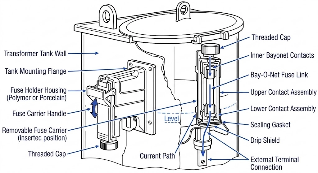
A Bay-O-Net fuse assembly is a draw-out protection device used in liquid-filled distribution transformers. It includes a housing, removable fuse holder and compatible fuse link. This guide explains the component choices and information needed for procurement; final selection requires the documentation for the exact assembly and transformer.
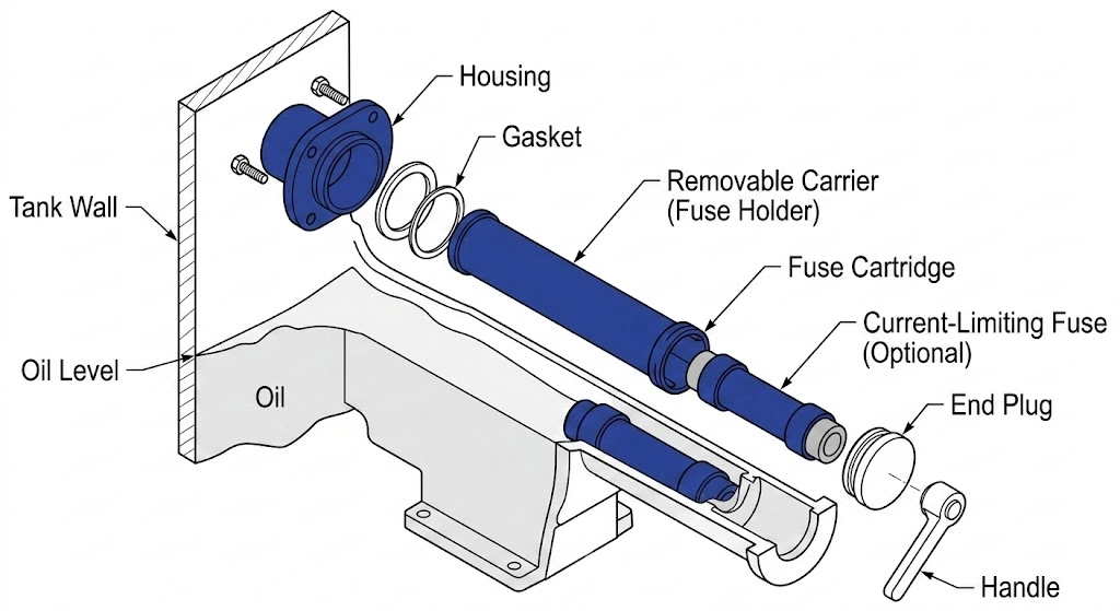
Identify the housing, holder, cartridge and fuse link separately when ordering. A matching appearance does not establish interchangeability. Confirm part numbers, mounting arrangement and the approved combination with the supplier before specifying a replacement.
Figure 01: Housing, removable holder and fuse cartridge shown schematically; confirm details against the selected assembly drawing.
Compare Bay-O-Net fuse assemblies alongside the other transformer accessories in your design. Ask for the assembly drawing, fuse-link selection table and applicable time-current curves rather than selecting from a voltage label alone.
Application Scope: Where to Specify 15/25kV Assemblies
Specifying the correct Bay-O-Net fuse housing and carrier requires matching the assembly’s dielectric and continuous current capabilities to the distribution transformer’s operational parameters. These assemblies are primarily deployed in liquid-immersed pad-mounted and pole-mounted transformers serving residential, commercial, and industrial utility loads.
Voltage Class and BIL Ratings
For projects described as 15 kV or 25 kV, provide the actual system voltage, grounding arrangement and required insulation level. Confirm the manufacturer’s voltage designation and application limits for the housing and fuse link; a network voltage class is not a complete product specification.
As a manufacturer-specific example, Eaton installation manual MN132003EN lists 150 kV BIL for its 23 kV assembly and 200 kV BIL for its 38 kV assembly. These ratings apply to the documented Eaton products, not automatically to ZeeyiElec products or every assembly described as 15/25 kV. Obtain the selected model’s approved datasheet and insulation requirements.
Transformer Capacity and Load Currents
Bay-O-Net assemblies are not universal for all transformer sizes; their application is strictly bound by continuous current-carrying limits and heat dissipation capabilities within the insulating oil.
Do not use a universal kVA range or a single 160 A limit to approve an assembly. Specify the continuous-current capability, loadbreak capability and fault-interrupting capability separately. Each must be checked for the selected housing, fuse link and application.
When selecting the assembly for a specific project, procurement teams and electrical engineers must verify that the steady-state load current, plus any utility-mandated overload margins, does not exceed the thermal limits of the fuse carrier contacts. Pushing an assembly beyond its continuous thermal rating leads to localized heating, accelerated carbonization of the oil near the tank wall, and eventual dielectric breakdown of the housing itself.
Selection Check: Load Current Is Only the Starting Point
For a balanced three-phase transformer, primary line current is I = S / (√3 × V), using kVA and line-to-line kV. A 2,500 kVA unit draws approximately 116 A at 12.47 kV or 347 A at 4.16 kV. These calculations describe load current only; neither proves that a particular fuse assembly is suitable.
Expert Insight: BIL Verification
Record the required BIL, power-frequency withstand level and mounting clearances in the RFQ. Check these against the selected assembly drawing and the transformer insulation-coordination requirements.
Fuse Link Selection: Current Sensing vs. Dual Sensing
Choose the fuse-link family using the transformer loading requirements and the supplier’s application tables. Current-sensing and dual-sensing links are distinct choices, and their ratings and curves should be identified by catalog number.
Current-Sensing Fuse Links
Use the current-sensing link’s published time-current curve to assess its response to overcurrent.
Request the exact link curve and its stated reference conditions. Avoid assigning a clearing time from the nominal ampere rating alone. Include transformer inrush, permissible overload and the currents referred to the primary side in the protection review.
Dual-Sensing Fuse Links
Dual-sensing links provide an essential secondary layer of protection by responding to both electrical overcurrents and elevated transformer oil temperatures.
Use the selected dual-sensing link’s application data to evaluate temperature and current response together. Do not assume a universal 145°C operating threshold or treat the link as a standalone temperature switch.
After an operation, record loading, fluid condition and the fault investigation results before selecting a replacement. Repeated replacement without identifying the cause does not resolve a protection or application problem.
The Two-Fuse Protection Scheme: Coordinating with Current Limiting Fuses
A common protection arrangement pairs the Bay-O-Net with a series-connected backup current-limiting fuse. Specify the complete approved protection scheme, not only the replaceable link.
Series Coordination Logic
The Bay-O-Net interrupting rating varies with voltage and the approved fuse-link/fluid combination. Eaton’s MN132003EN, for example, lists different interrupting ratings at 8.3, 15.5 and 23 kV. Therefore, 3,500 A must not be used as a universal coordination threshold.
Provide the available fault current and the proposed backup-fuse catalog number to the protection engineer. Ask the supplier for the approved pairing and coordination documentation for that combination.
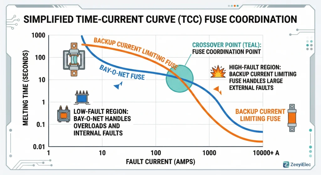
Figure 02: Conceptual coordination illustration, not a manufacturer time-current curve for product selection.
Review the minimum-melting and total-clearing curves, the backup fuse’s minimum interrupting current and the manufacturer’s coordination criteria. A visually convenient curve intersection is not proof of coordination. For related background, see our Bay-O-Net and current-limiting fuse coordination article; use manufacturer data for final engineering decisions.
Service Planning: Use the Exact Manufacturer Procedure
This procurement guide is not an extraction or switching procedure. Qualified personnel must follow the transformer and fuse manufacturer’s instructions and the site’s isolation procedure. Opening a loadbreak switch alone does not prove that all parts are de-energized or isolated from backfeed.
Venting Transformer Pressure
Eaton’s re-fusing manual MN132002EN requires tank-pressure relief before Bay-O-Net operation. Use the specified equipment procedure; do not rely on a generic pressure or oil-temperature threshold from an article.
Confirm Mounting Type and Service Instructions
Sidewall-mounted and cover-mounted assemblies have separate instructions. Use the procedure for the exact installation, including the prescribed tool, movement and fluid-drain sequence. Do not apply a generic 2–3 inch pull or fixed 5–10 second pause to every assembly.
Managing Oil Viscosity in Cold Environments
Record the fluid type and expected service-temperature range when requesting a replacement. Ask the equipment supplier for any applicable cold-weather limitations; do not invent an extended drain time from ambient temperature alone.
Service Check: Unexpected Resistance
Unexpected resistance requires assessment under the equipment’s service procedure. It does not, by itself, establish welded contacts or a specific overload history. Do not use this guide to justify additional pulling force.
Service Check: Replacement Documentation
Keep the replacement part number, approved fuse-link combination, assembly drawing and current service instructions with the maintenance record. Resolve missing compatibility information before returning the equipment to service.
Sourcing 15/25kV Bay-O-Net Assemblies for Your Next Project
For a useful quotation, send transformer kVA, phase configuration, primary voltage and grounding arrangement, required BIL, load profile, prospective fault current, fluid type and mounting drawing. For a replacement, add photographs and the existing housing, holder and fuse-link part numbers.
Ask the supplier to identify the proposed assembly and link separately, provide the relevant ratings and time-current curves, and document compatibility with the backup protection. Record any deviations from the project specification explicitly.
Can a Bay-O-Net fuse be replaced while the transformer is energized?
Some assemblies have a specified loadbreak capability, but this is not blanket permission for energized replacement. Use the exact manufacturer procedure and site authorization. Eaton MN132002EN gives application restrictions and separate service procedures; neither a generic 100 A rule nor merely opening a switch establishes safe isolation.
What causes a dual-sensing Bay-O-Net fuse to operate if there is no electrical fault?
Dual-sensing links respond to current and fluid temperature. Review the selected link’s application data and investigate the operating conditions; do not diagnose the event from an assumed universal trip temperature.
Does the transformer oil level affect Bay-O-Net operation?
Yes. Check the manufacturer’s specified fluid level and approved fluid type. An incorrect level can compromise operation; use the equipment instructions rather than a generic minimum level or fault-current threshold.
What is the difference between a 15kV and a 25kV Bay-O-Net housing?
These labels describe an intended voltage class, but do not establish interchangeability or physical dimensions. Compare the exact housing and link voltage ratings, insulation levels, mounting dimensions and approved applications.
Can I use a Bay-O-Net fuse without a backup current limiting fuse?
It depends on the approved protection scheme and available fault current. Eaton MN132003EN specifies an isolation link or energy-limiting fuse for its documented 23 kV arrangement, and a rated energy-limiting fuse for its 38 kV arrangement. Do not omit series protection or transfer these requirements to another model without confirmation.
How does oil temperature affect the extraction of the fuse carrier?
Fluid viscosity changes with temperature, but this does not establish a universal extraction force or waiting period. Use the exact service manual and obtain manufacturer guidance for the specified fluid and temperature range.
yoyo shi
Yoyo Shi writes for ZeeyiElec, focusing on medium-voltage accessories, transformer components, and cable accessory solutions. Her articles cover product applications, technical basics, and sourcing insights for global electrical industry buyers.





 English
 한국어
한국어 العربية
 Español
 हिन्दी
 தமிழ்
தமிழ் Deutsch (Sie)
 Français
 Português do Brasil
 Русский