What Is Thermal Rise in a Low Voltage Bushing and Why It Matters
LV bushing thermal rise is the temperature increase above ambient that builds up in the conductor, contact interfaces, and surrounding insulation of a low voltage bushing as load current flows through it. It comes from resistive (I²R) heating in the conductor and stud, plus smaller contact and dielectric losses at the terminal interfaces—and it is the single factor most likely to shorten a bushing’s service life if it is underestimated at the specification stage.
Unlike a mechanical failure, excessive thermal rise rarely causes an immediate fault. Instead, it accelerates insulation aging in a way that is well documented across transformer and switchgear literature: as a widely cited engineering rule of thumb, every 8–10°C of sustained temperature above the insulation’s rated class roughly halves its expected service life. A bushing running 15°C hotter than its design point for years does not fail in year one—it fails years ahead of schedule, often written off as “normal wear” rather than traced back to a sizing decision made at RFQ stage.
This guide covers what causes thermal rise in low voltage bushings, how it is tested and rated, what current and ambient factors engineers should account for when specifying, the field signs that indicate a problem, and practical mitigation steps. Low voltage bushings sit within the broader transformer accessories category, and buyers scoping a full accessory package can start from the transformer accessories selection guide for category-wide context before narrowing to thermal performance specifics.
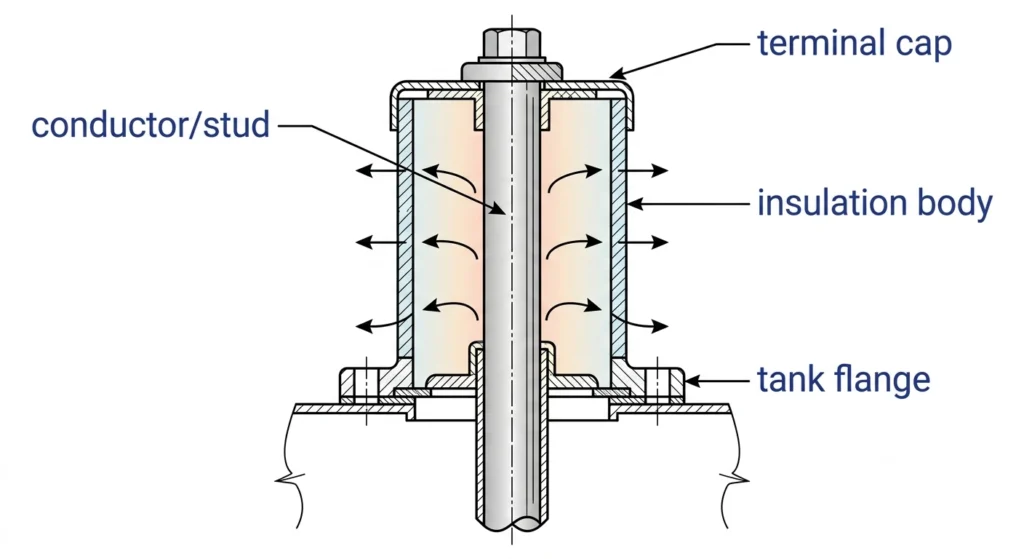
Heat flow paths inside an LV bushing, from the conductor through the insulation to the surrounding air.
What Causes Temperature Rise in LV Bushings?
Temperature rise is not a single phenomenon—it is the sum of several independent heat sources, and treating it as one number hides which one is actually the problem on a given installation.
Resistive (I²R) Losses in the Conductor
The dominant heat source in most LV bushings is I²R loss in the current-carrying stud or conductor: heat generated scales with the square of current, so a 20% increase in load current can raise resistive heating by roughly 44%, not 20%. Conductor cross-section, material (copper vs. aluminum), and length all set the baseline resistance this loss is calculated against.
Contact and Dielectric Losses
Contact resistance at bolted or crimped terminal interfaces adds localized heating that does not show up in a bulk conductor temperature reading—a loose or under-torqued connection can run 20–30°C hotter than the conductor body around it, even when the conductor itself is well within rating. Dielectric losses in the surrounding insulation are typically small at LV voltage levels but rise with insulation aging or moisture ingress, compounding whatever resistive heat is already present.
[Expert Insight: Where Heat Actually Concentrates]
Terminal connections, not the conductor midpoint, are the most common hot-spot location in field thermography
Aluminum-to-copper terminal interfaces need bimetallic hardware or anti-oxidant compound to avoid long-term contact resistance drift
A single under-torqued bolt can produce a hot spot that a correctly sized conductor cannot compensate for
How Is Temperature Rise Tested and Rated?
Temperature rise is verified with a type test, not assumed from a datasheet calculation: the bushing is loaded at rated current until it reaches thermal equilibrium (typically when the temperature rise rate falls below roughly 1°C per hour), and the resulting rise above ambient is measured at the conductor, terminal, and any embedded insulation reference points.
The relevant reference is IEC 60137:2017, Clause 4.8 (Maximum values of temperature and temperature rise above ambient air), which sets the framework for how rise is measured and reported by insulation and construction class. The specific permissible rise limits vary by insulation class and construction type, so buyers should request the tested rise value for their exact bushing construction rather than assuming a single figure applies across all classes &mdash.
A routine test at rated current does not always reproduce field conditions exactly—ambient enclosure temperature, airflow, and adjacent heat sources (such as nearby fused switches or tap changers) can all push actual in-service temperature above the type-test figure, which is why derating for real installation conditions matters as much as the base rating itself.
What Current Rating and Ambient Factors Should Engineers Account For?
Specifying purely to nameplate load current, without margin for ambient and enclosure conditions, is the most common way thermal rise problems get built into a project before the bushing is even ordered.
Ambient Temperature and Enclosure Effects
A bushing rated for a 40°C ambient will run measurably hotter in an unventilated kiosk enclosure exposed to direct sun, where internal air temperature can exceed outdoor ambient by 10–15°C. Buyers should specify based on the enclosure’s expected internal temperature, not the regional weather average.
Load Growth and Duty Cycle
Current rating should reflect forecast load growth over the transformer’s service life, not just today’s connected load—a bushing sized with zero margin against present-day peak demand leaves no thermal headroom once load grows even modestly. Where the duty cycle includes regular short-time overloads (common in distribution networks with seasonal demand swings), the thermal time constant of the bushing matters: a bushing with a short thermal time constant heats up faster during an overload but also cools faster once load drops, while a larger, higher-mass bushing responds more slowly in both directions.
[Expert Insight: Margin Beyond Nameplate]
Size current rating against forecast peak load, not today’s nameplate figure
Confirm enclosure internal temperature, not outdoor ambient, when specifying temperature class
Request the manufacturer’s derating curve for altitude and ambient combined, not each applied separately
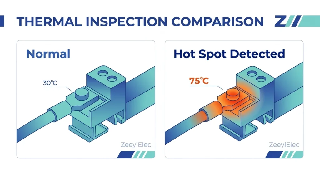
A loosened terminal connection produces a localized hot spot well above the surrounding conductor temperature.
What Are the Field Signs of Excessive Thermal Rise?
Thermal rise problems are rarely silent. Discoloration of insulation near the terminal, a faint but persistent odor at the bushing interface, or a terminal that feels warm to the touch well after load has dropped are all signs worth investigating before they become a failure event. Across LV bushing field investigations, the root cause traced most often is a terminal connection that was never re-torqued after commissioning—not a manufacturing defect in the bushing itself.
Diagnostic Checklist
Infrared thermography during peak load, comparing terminal temperature against the conductor body and adjacent phases
Torque check on bolted connections—a connection that has loosened over thermal cycling is the single most correctable cause of localized hot spots
Visual inspection for discoloration, surface crazing, or a chalky residue on insulation near the terminal
Review of load history against the bushing’s original current rating to confirm it still has margin
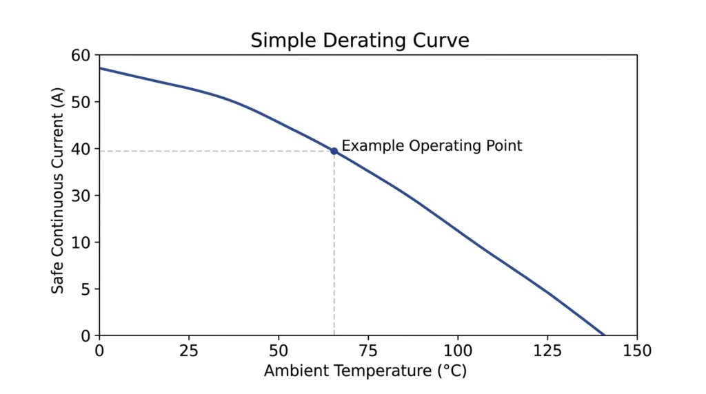
Safe continuous current rating decreases as ambient enclosure temperature rises.
Field teams working through a broader diagnostic sequence, not just thermal symptoms, can reference ZeeyiElec’s field failure diagnosis workflow for a structured approach that covers thermal, dielectric, and mechanical failure indicators together rather than investigating each in isolation. On installations where the same terminal also carries a cable termination, thermal and mechanical stress at that joint should be evaluated together with the paired cable accessories, since a poorly seated cable lug can be the actual source of a hot spot attributed to the bushing.
How Can Thermal Rise Be Mitigated in Design and Installation?
Most temperature rise problems trace back to one of three decisions: undersized conductor cross-section for the actual duty, a terminal interface that was not torqued or maintained correctly, or an enclosure that traps heat the original specification did not account for.
Design-Stage Mitigation
Specify conductor cross-section with margin above calculated nameplate current, not at the calculated minimum
Confirm terminal plating and bimetallic hardware compatibility before finalizing a mixed copper/aluminum interface
Request the manufacturer’s tested rise curve rather than relying on a single rated-current data point
Installation and Maintenance Mitigation
Torque all terminal connections to the manufacturer’s specified value and re-check after initial thermal cycling
Ensure enclosure ventilation matches the design assumption used for the bushing’s ambient rating
Schedule periodic infrared thermography on critical connections rather than waiting for a visible symptom
Infrared thermography can catch a developing hot spot before it becomes a failure.
Frequently Asked Questions
What is a normal temperature rise for an LV bushing?
Acceptable temperature rise depends on the bushing’s insulation class and construction type, so there is no single universal number; buyers should request the manufacturer’s tested rise value for their specific construction rather than assuming a generic figure applies.
How much does ambient temperature affect a bushing’s safe current rating?
Ambient temperature directly reduces the safe operating margin—an enclosure running 10–15°C above outdoor ambient effectively narrows the gap between operating temperature and the insulation’s rated limit, which is why enclosure conditions should be specified alongside voltage and current class.
Can a loose terminal connection cause thermal rise even if the conductor is correctly sized?
Yes—contact resistance at a loose or under-torqued terminal can produce a localized hot spot 20–30°C above the surrounding conductor temperature, independent of whether the conductor itself is adequately sized for the load.
How often should thermal rise be checked after installation?
Most operators combine infrared thermography during peak load with periodic maintenance inspections; exact intervals vary by criticality of the installation and local utility maintenance policy, so specific scheduling should follow the operator’s own asset management program.
Does aluminum-to-copper terminal interface increase thermal rise risk?
It can, if bimetallic hardware or anti-oxidant compound is not used—dissimilar metal interfaces are more prone to long-term contact resistance drift than same-metal connections, which compounds over repeated thermal cycling.
Is a higher current rating always the safer choice when specifying a bushing?
Not necessarily from a cost or fit perspective, but specifying with margin above forecast peak load—rather than at the calculated minimum—is generally the safer approach for long-term thermal performance, since it preserves headroom as load grows over the transformer’s service life.
yoyo shi
Yoyo Shi writes for ZeeyiElec, focusing on medium-voltage accessories, transformer components, and cable accessory solutions. Her articles cover product applications, technical basics, and sourcing insights for global electrical industry buyers.







 English
 한국어
한국어 العربية
 Español
 हिन्दी
 தமிழ்
தமிழ் Deutsch (Sie)
 Français
 Português do Brasil
 Русский