A bushing well commissioning checklist and its accompanying record confirm a distribution transformer’s bushing well interface is dielectrically sound, mechanically seated, and traceable to its purchase order before the unit is energized.
The bushing well interface is a separable connector, not a single molded part — a permanent epoxy or porcelain well bonded to the tank wall, and a removable EPDM or silicone insert that seats inside it to complete the dielectric path. On a typical 15/25kV class transformer, the assembly is rated for continuous current around 200 A and must hold that rating for a 25–40 year service life. A record that confirms “insert installed” without documenting seating depth, torque, or nameplate cross-check leaves that service life unverified at the one point correction is still cheap.
Why Commissioning Records Differ from Installation Checklists
An installation checklist is procedural. A commissioning record is evidentiary — it logs seating depth, torque reading, and insulation resistance against class-specific values, with a name and date attached. In field audits, transformers with checklists but no commissioning record are disproportionately the ones where a mismatched insert passes initial inspection but fails within the first operating season.
What the Record Must Prove Before Energization
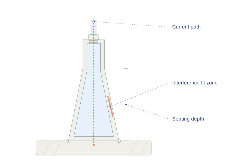
Three things: the physical interface matches the transformer’s rated voltage class and BIL, the mechanical assembly meets its torque and seating specification, and the completed connection passes an insulation resistance check appropriate to a 200A bushing well and insert rated for 15/25kV or 15/25/35kV service.Cross-section of the bushing well and insert interface, showing the epoxy well bonded to the tank wall and the seated dielectric contact plane.
[Expert Insight]
A record with checkbox-only fields isn’t evidence — a reviewer needs a measured number
The nameplate carries kVA and voltage ratio, never insert-level BIL or interface class
Treat the commissioning record as the last gate before the 25–40 year service clock starts
Pre-Commissioning Verification Fields
Before an insert is accepted into the record, its physical and documentary parameters must be cross-checked against the transformer’s nameplate and purchase order — the source of most recordkeeping gaps.
Voltage Class and BIL Cross-Check
The record must confirm the insert’s rated voltage class matches the transformer’s system voltage, not just its nominal rating. A 15/25kV class well accepts an insert rated for that same dual-voltage range; a single-rated 15kV insert in a 25kV-designated well is a mismatch that won’t surface in a simple continuity check.
The dielectric withstand level for the interface must correlate with the system’s Basic Impulse Level, typically in the range of 95 kVp to 150 kVp BIL for 15/25kV class distribution equipment.
Interface Dimension and Compatibility Fields
The record should capture the well’s interface dimension standard — well bore diameter, insert taper profile, and the specific product family reference — since an insert off by a few millimeters at the mating plane won’t seat despite carrying the correct voltage rating on its label.
Documentation and Traceability Fields
Every accepted insert should be logged against its manufacturing batch number, FAT reference, and purchase order line item. This traceability field lets a field team isolate a defective batch across multiple transformers rather than treating each failure as isolated — relevant given that 15–25% of accessory-related outages across a fleet often trace back to a shared root cause.
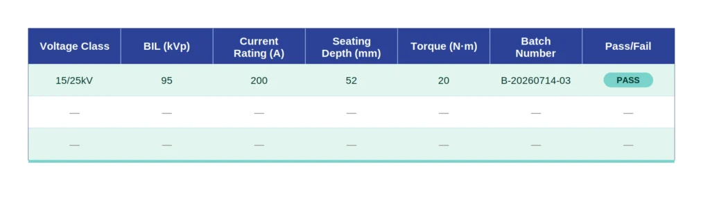
A sample bushing well commissioning record table, listing voltage class, BIL, current rating, seating depth, torque, and pass/fail fields.
Physical Seating and Torque Verification Steps
Documentation only carries weight if the physical assembly behind it was verified correctly. This is where most real-world seating errors surface — usually not from a wrong part, but an incompletely seated one.
Insertion Depth and Alignment Check
The insert must seat to full engagement depth, verified with a go/no-go depth gauge rather than visual inspection, since the interference fit can appear flush at the collar while the dielectric contact zone underneath remains under-seated. Full seating depth commonly falls in the 45 mm to 65 mm range depending on voltage class, and the record should capture the measured value. An insert that reads seated by eye but sits 3–5 mm short of full depth is a common cause of early tracking failure once energized.
Torque Staging Sequence
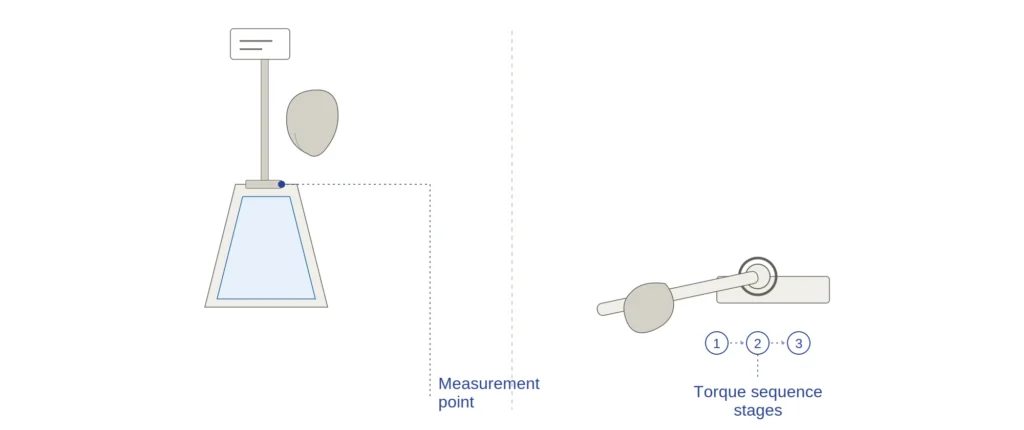
Bolted or clamped retention hardware should be torqued in stages rather than driven to final value in one pass, to avoid cocking the insert off-axis: roughly 30% of final torque, an alignment check, then completion to the full specified value — commonly 15 N·m to 25 N·m for this hardware class, though the exact figure depends on the specific assembly.
Lubricant and Seal Inspection
A thin, uniform layer of compatible dielectric lubricant should be visible at the interference fit line after seating, with no gaps, bunching, or displaced lubricant beyond the seal boundary — a field-observed sign that an insert may have been forced past a misalignment rather than seated cleanly.
A technician verifies bushing well insert seating depth with a gauge, then applies staged torque to the retention hardware.
Field Case: A Commissioning Record That Caught a Mismatch
A structured commissioning record earns its place at the moment it catches something a visual walkthrough would have missed.
What the Record Flagged
On a pad-mounted 25kV class transformer, the crew completed insert seating and torque without incident — smooth thread, visual seating depth, no misalignment. The commissioning record required a cross-check between the insert’s batch documentation and the purchase order line item before sign-off. That check showed the insert carried a continuous operating rating of 8.7 kV rather than the dual-rated 8.7kV/14.4kV specified for the site’s 15/25kV service — a lower-voltage-class insert that shared the same 200A bushing well interface dimensions and seated identically, so the substitution was invisible during physical installation.
Corrective Action Taken
The commissioning engineer withheld sign-off, flagged the discrepancy against the batch traceability field, and the correct dual-rated 15/25kV insert was sourced and reinstalled before energization. The replacement added roughly four days to the schedule — acceptable against the alternative: an interface entering service below its intended operating voltage class, on a component with a 25–40 year expected life. Only the documentary cross-check caught it; the physical installation looked correct throughout.
Electrical Testing and Sign-Off Criteria
Once seating and documentary checks are complete, the record moves to electrical verification and formal sign-off — the section auditors and buyers typically review first.
Insulation Resistance and Continuity Checks
Before energization, the interface should be tested for insulation resistance with a megohmmeter appropriate to the voltage class, referenced against manufacturer routine test values rather than one fixed threshold across all classes.
For a 15/25kV class interface, a healthy insulation resistance reading typically falls at or above 1,000 MΩ to 5,000 MΩ at ambient temperature, though the exact acceptance threshold depends on the insert material (EPDM vs. silicone) and site humidity at time of test.
A continuity check across the current-carrying path confirms the interface won’t introduce unexpected resistance at the 200 A rated load — a low but non-zero reading is often the first indicator of an under-seated insert that passed the depth gauge but missed full contact area. This general approach to dielectric verification before energization aligns with the diagnostic field testing framework described in IEEE Std C57.152, the IEEE guide for diagnostic field testing of fluid-filled power transformers, regulators, and reactors.
Witness and Approval Requirements
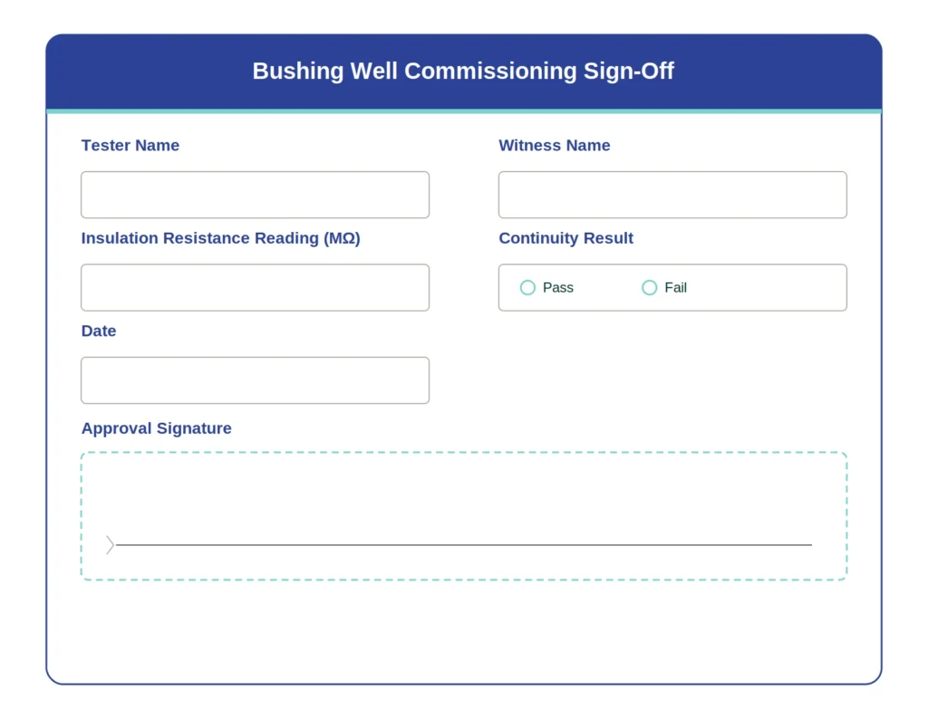
The record should capture who performed each measurement, who witnessed it on buyer-inspected projects, and the sign-off date — a field that distinguishes a supplier-executed test from an independently verified one if a dispute over the transformer accessories specification arises later.A commissioning sign-off block capturing tester and witness names, insulation resistance reading, continuity result, and approval date.
[Expert Insight]
A borderline megohmmeter reading without logged temperature/humidity is unverifiable later
Continuity checks catch under-seated inserts that pass the depth gauge but miss full contact area
Buyer-witnessed sign-off matters most when a dispute surfaces after the fact, not during the test
Common Recordkeeping Mistakes That Delay Energization
An incomplete or ambiguous record can stall energization on its own — often discovered only when sign-off is rejected during review, not during installation.
Missing or Ambiguous Fields
A box marked “seated correctly” carries no verifiable information; a recorded value of 52 mm against a specified 45–65 mm range gives a reviewer something to confirm. The same applies to BIL and voltage class — recording “15kV” without specifying single- or dual-rated 15/25kV creates exactly the ambiguity behind the mismatch in the field case above. Records with checkbox-only entries are disproportionately the ones sent back for rework during buyer review.
Skipped Environmental Condition Notes
Insulation resistance readings are temperature- and humidity-sensitive, so a record without ambient conditions at time of test is hard to validate later. A reading at 5°C in low humidity isn’t comparable to one at 35°C in coastal humidity, and this field is commonly skipped on retrofit projects — a gap that’s difficult to close once the transformer is already energized.
Get a Ready-to-Use Bushing Well Commissioning Template
A complete commissioning record pulls nameplate cross-checks, seating and torque measurements, insulation resistance readings, and sign-off fields into one traceable document — building that structure from scratch is where most gaps above tend to creep in.
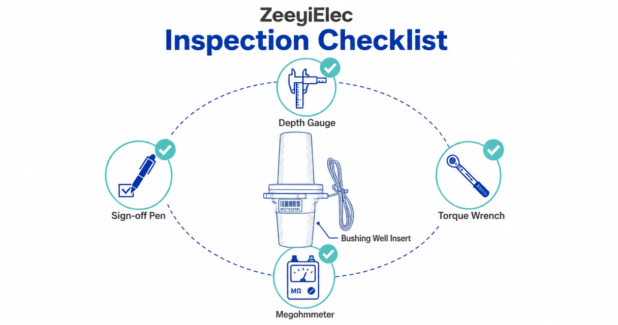
ZeeyiElec’s technical support team can provide a ready-to-use commissioning record template for 15/25kV and 15/25/35kV class 200A bushing well and insert assemblies, structured around the verification fields covered in this guide. For projects sourcing both transformer- and cable-side accessories on the same job, the template can be adapted to reference matching interface data from the cable accessories series where an insert connects directly to a loadbreak elbow termination.
Reach out with your transformer’s voltage class, insert quantity, and target commissioning date, and the technical team can return a template pre-populated with the correct acceptance ranges for your project.
Frequently Asked Questions
How long does a bushing well commissioning record need to be retained?
Most utilities and EPC contractors retain commissioning records for the life of the asset, often 25–40 years, since the record is the only evidence of the interface’s condition at energization if a failure investigation occurs decades later.
What voltage classes require a full commissioning record versus a simplified check?
Medium-voltage interfaces in the 15kV to 35kV class generally warrant a full record with measured values, while lower-stakes low-voltage connections may use a simplified checklist, though project specifications and buyer requirements ultimately determine the applicable level.
Who should sign off on a bushing well commissioning record?
The technician who performed the physical verification typically signs first, with a second signature from a site engineer or buyer-appointed witness required on projects where third-party inspection was specified in the contract.
What is the difference between a commissioning record and a FAT report?
A factory acceptance test (FAT) report verifies the insert met its design specification before shipment, while a commissioning record verifies the same interface was correctly installed and tested on site after arrival — both cover the same component but at different stages.
Can a bushing well commissioning checklist be reused across voltage classes?
The general structure of the checklist carries across voltage classes, but the acceptance values for BIL, seating depth, and insulation resistance change by class, so each project’s record should reference the specific rated parameters rather than a generic threshold.
What causes a bushing well to fail commissioning verification?
The most common causes are a BIL or voltage class mismatch between the insert and the transformer’s rated interface, incomplete seating depth, and insulation resistance readings that fall below the expected range for the installed material and site conditions.
Does ambient temperature affect commissioning test results?
Yes, insulation resistance readings shift with ambient temperature and humidity, which is why a commissioning record should log site conditions alongside the measured value rather than the reading alone.
yoyo shi
Yoyo Shi writes for ZeeyiElec, focusing on medium-voltage accessories, transformer components, and cable accessory solutions. Her articles cover product applications, technical basics, and sourcing insights for global electrical industry buyers.





 English
 한국어
한국어 العربية
 Español
 हिन्दी
 தமிழ்
தமிழ் Deutsch (Sie)
 Français
 Português do Brasil
 Русский