This LBS commissioning checklist covers the structured verification process performed after installation and before energized service — confirming that a loadbreak switch (LBS) operates within its rated mechanical and electrical parameters before it carries live load current.
This LBS commissioning checklist treats the two configurations differently, since their structural differences drive what gets inspected in the field.
Two-Position Switch Function
A two-position LBS provides a single make/break operation between open and closed states, generally used for simple sectionalizing or transformer isolation points. Verification centers on a clean travel path and full release of the stored-energy mechanism at each end of travel — incomplete travel of even a few millimeters can leave contacts partially engaged.
Four-Position Sectionalizing Switch Function
A four-position sectionalizing LBS adds intermediate switching states to support loop-feed or alternate-source configurations, commonly used where a transformer must isolate from one source while remaining connected to another for downstream continuity. Each position transition engages a different internal contact path, so indicator alignment must be confirmed at all four states, not just the extremes.
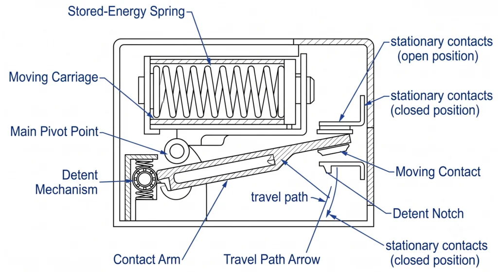
Relevant construction and rating references are available on ZeeyiElec’s loadbreak switch product page.Cutaway view of the stored-energy quick-action mechanism, showing contact travel path and detent engagement points across both switch configurations.
Field Notes
Four-position units show more detent wear in the first year, simply from cycling through more intermediate states.
A handle that feels complete doesn’t guarantee full contact seating — indicator cross-checks catch what travel alone misses.
Worn or under-torqued mechanisms are the most common cause of a false-complete switching feel.
Pre-Commissioning Preparation and Documentation
Before physical inspection begins, confirm the switch delivered to site matches the specification approved during procurement. This prevents a correct-looking switch being checked against the wrong voltage class or current rating — an error that often only surfaces during electrical testing, after mechanical checks have already consumed crew time.
Drawing and Nameplate Verification
Cross-check the nameplate against approved drawings for voltage class (commonly 15/25 kV or 38/40.5 kV), continuous current rating (typically 630 A), and configuration type. Confirm the serial number matches the factory test report, since mismatched documentation can indicate a substitution during transit or storage. Where alignment with a procurement framework is needed, ZeeyiElec’s transformer accessories RFQ checklist outlines the parameters that should already be confirmed at ordering.
Tooling, PPE, and Hook-Stick Readiness
Verify the insulated hook stick rating matches the system voltage class with adequate margin, and inspect it for surface contamination or damage — a compromised hook stick is an overlooked cause of failed switching attempts. Confirm torque wrenches are calibrated within tolerance and insulation resistance test equipment has a valid calibration date. PPE selection should follow the site’s arc-flash study rather than a generic assumption, since incident energy varies by installation.
Staging documentation checks the day before physical work avoids the schedule delay a mid-installation nameplate mismatch can cause.
Field Checklist for 2-Position LBS
This checklist follows a fixed sequence: mechanical operation, contact verification, and documentation sign-off. Skipping ahead under schedule pressure increases the risk of missing a partial-travel condition that only shows up under load.
Mechanical Operation and Handle Travel Check
Confirm the handle moves freely through its full arc without binding, typically requiring 15–25 lb-ft of torque depending on mechanism design and ambient temperature.
Operate open-to-closed and back using the rated hook stick, confirming the stored-energy mechanism snaps through full travel rather than stalling.
Verify the position indicator visually matches actual contact state at both positions — don’t rely on handle position alone.
Check mounting bolt torque against spec, commonly 25–40 Nm for standard pad-mount brackets, since under-torqued mounting can cause misalignment.
Insulation and Contact Verification Steps
Perform an insulation resistance test between phases and to ground in the open position; acceptable readings generally fall in the hundreds of megohms for a clean, dry installation.
Measure contact resistance in the closed position; values well above baseline can indicate contamination or pitting.
Inspect visible contact surfaces for discoloration or pitting before final closure.
Record readings against the factory baseline and flag any deviation exceeding 20% before energization.
Field checks on pad-mounted units consistently show that most failures trace back to step 3 — indicator mismatch — rather than actual contact damage, which is why visual confirmation is treated as non-negotiable rather than a formality.
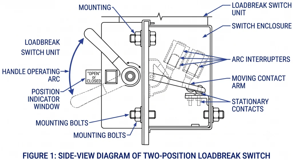
Annotated diagram of a two-position switch identifying handle travel arc, indicator alignment points, and mounting bolt torque check locations
Field Checklist for 4-Position Sectionalizing LBS
This checklist extends the two-position sequence to cover intermediate switching states, since each transition engages a distinct contact path. It commonly takes 40–70 minutes per unit versus 20–40 minutes for a two-position switch, and rewards a methodical, position-by-position approach.
Sequential Switching Verification
Operate through all four positions in sequence, confirming smooth, complete travel without hesitation.
At each position, verify the stored-energy mechanism fully releases before the handle is considered seated — a mechanism that “feels done” at 90% travel is a common source of latent failures.
Cycle the switch 2–3 times through the full sequence to confirm repeatable behavior.
Confirm operating torque stays consistent across all four positions; a spike at one position often points to localized interference.
Position Indicator and Interlock Alignment
Cross-check the indicator against actual contact state at each of the four positions individually.
Verify mechanical or key interlocks prevent invalid position combinations, particularly for loop-feed configurations.
Perform insulation and contact resistance testing at each relevant position pair, since values can vary between contact paths on the same unit.
Document indicator alignment findings separately from mechanical travel results, since they require different corrective actions.
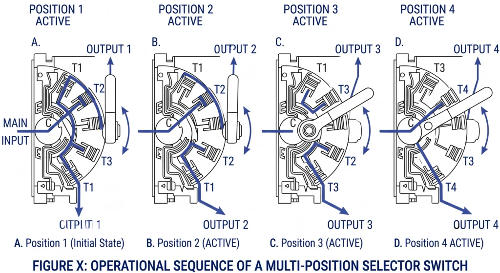
Related sectionalizing versus tap-changer boundaries are covered in ZeeyiElec’s loadbreak switch vs off-circuit tap changer comparison.Diagram of the four sequential switching states in a sectionalizing loadbreak switch, with indicator alignment and interlock points labeled.
Field Notes
Loop-feed installations put more cycles on intermediate positions, accelerating detent wear versus simple two-position points.
Torque inconsistency across positions is a better early-warning sign than a single failed cycle.
Document mechanical and indicator findings separately — they point to different fixes.
Electrical Testing and Acceptance Criteria
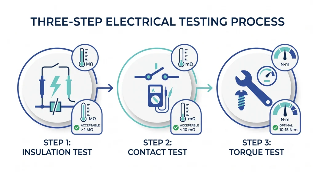
Mechanical checks confirm an LBS moves correctly; electrical testing confirms it can switch without excessive resistance or leakage under service conditions. A switch can pass every mechanical check and still fail electrically if contacts are contaminated or insulation has absorbed moisture.
Insulation Resistance Test
Measures resistance between phases and to ground in the open position, typically the first electrical test after mechanical commissioning. Low readings often point to surface contamination or moisture ingress rather than a design defect.
Contact Resistance Test
Measured in the closed position and compared against the factory baseline. A significant increase typically signals pitting, oxidation, or incomplete contact seating.
Operating Timing/Torque Test
Confirms the stored-energy mechanism completes travel within a consistent time and torque window across repeated cycles — particularly relevant for four-position units, where inconsistent timing at one position can indicate localized interference.
Commissioning Acceptance Reference (Typical Field Ranges)
Test
Typical Acceptable Range
Flag for Investigation
Insulation Resistance (open position)
≥ 100 MΩ (dry, clean conditions)
< 100 MΩ or Δ > 30% vs baseline
Contact Resistance (closed position)
Within manufacturer baseline ± 20%
Δ > 20% from factory test report
Operating Torque (per position)
15–25 lb-ft (ambient temperature)
Inconsistent torque between positions
These are typical field references, not universal thresholds — acceptance should follow the factory test report and applicable pad-mounted switchgear standards such as IEEE C37.74, which governs pad-mounted load-interrupter switchgear requirements.
The deviation itself is diagnostic: insulation failures point toward moisture or contamination, while contact resistance failures point toward mechanical seating issues.
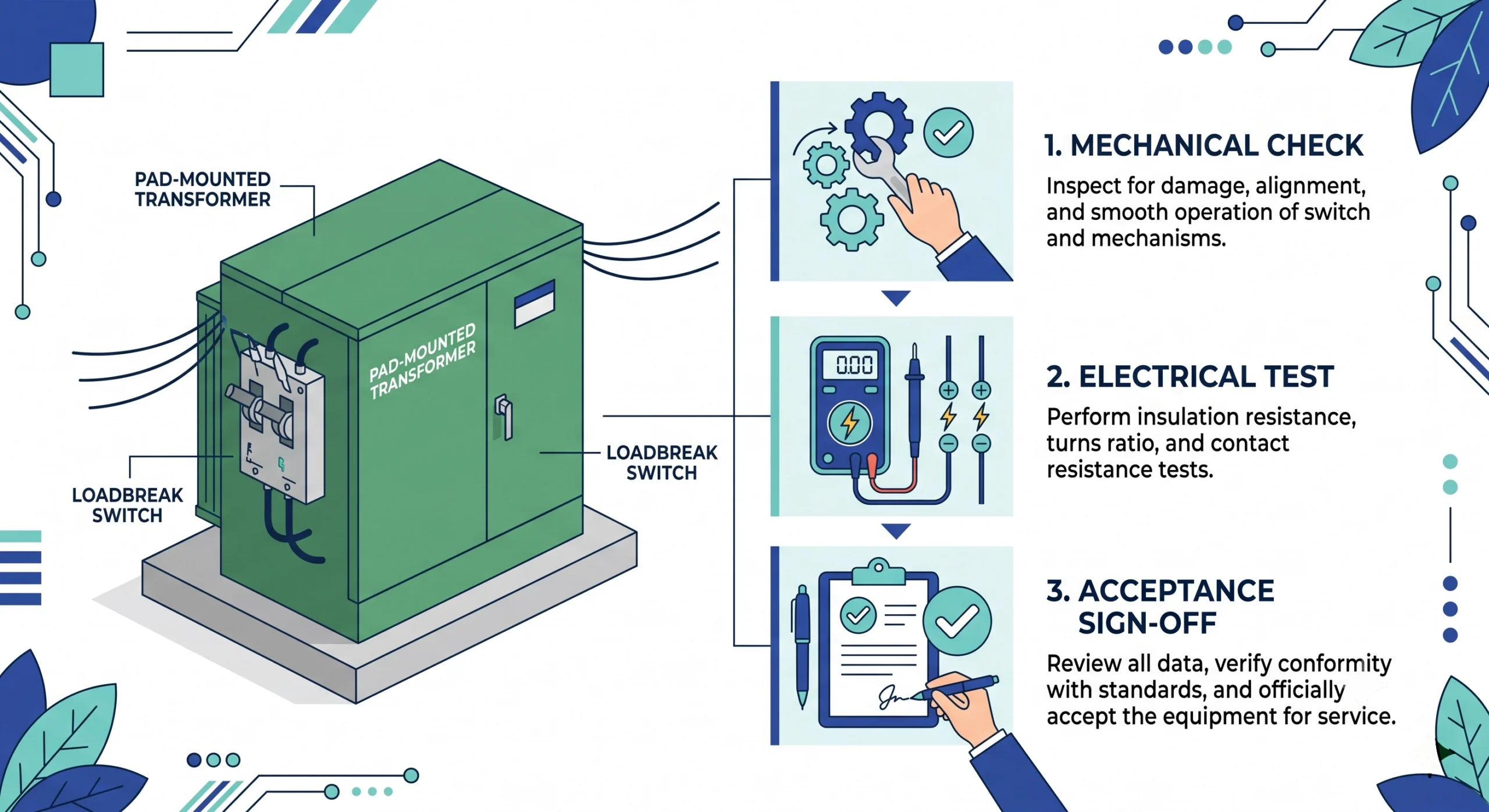
Flat-design summary of the insulation resistance, contact resistance, and operating torque test sequence with typical field acceptance ranges.
Common Failures and Field Corrections
Not every issue traces back to a defective switch. Most failed checks stem from installation-stage conditions — storage moisture, transit vibration, under-torqued mounting — rather than product defects. Separating these categories early saves diagnostic time.
Contact Misalignment and Indicator Mismatch
A mismatched position indicator is among the most frequently reported findings, particularly on four-position units, and usually traces to incomplete detent engagement rather than a broken indicator — the handle reaches its visual stop while the contact hasn’t fully seated. The fix is mechanical: re-torque mounting hardware, cycle the switch to reseat the detent, and re-verify alignment before retesting electrically. If misalignment persists, the mechanism likely needs replacement rather than adjustment.
Mechanism Binding or Incomplete Travel
Binding commonly links to contamination in the housing, thermal contraction in cold-weather commissioning, or unnoticed shipping damage. Units commissioned below roughly 0°C have shown noticeably higher operating torque than the same model at room temperature — worth accounting for against a baseline recorded under different conditions. Binding isolated to a single position on a four-position unit usually points to localized contact interference rather than a system-wide fault, and disassembly inspection is generally warranted.
position unit usually points to localized contact interference rather than a system-wide fault, and disassembly inspection is generally warranted.Across both failure types, avoid forcing a binding mechanism through additional cycles, since this can turn a correctable seating issue into permanent contact damage. Where a defect can’t be resolved through re-torquing and re-cycling, documenting it against ZeeyiElec’s field failure diagnosis workflow helps distinguish an installation-stage issue from a genuine manufacturing defect.
Get Commissioning-Ready Loadbreak Switches for Your Project
Good outcomes start before a switch reaches site — consistent factory-stage quality control, accurate documentation, and clear technical support during specification. ZeeyiElec supplies two-position and four-position sectionalizing switches rated for 15/25 kV and 38/40.5 kV classes at 630 A continuous current, engineered for hook-stick operation on oil-filled pad-mounted transformers.
Each unit ships with a factory test report covering insulation and contact resistance baselines, giving field teams a direct reference point rather than relying on generic ranges alone. For mixed-configuration projects, technical support can confirm compatibility between switch type, mounting interface, and voltage class before order placement.
Full specifications and configuration options are available on ZeeyiElec’s loadbreak switch product page. For projects also requiring cable accessories on the same network, ZeeyiElec’s cable accessories line covers cold shrink and heat shrink solutions for 10kV and 35kV class systems.
Project teams can request drawings, factory test report samples, and export documentation directly from ZeeyiElec’s engineering team.
Frequently Asked Questions
How long does commissioning a loadbreak switch typically take?
A single 2-position switch check typically takes 20–40 minutes per unit, while 4-position sectionalizing units can take 40–70 minutes due to sequential verification, depending on site access and crew experience.
What is the difference between commissioning a 2-position and 4-position LBS?
A 2-position check focuses on a single open/close travel and contact verification, while a 4-position switch requires checks across multiple sequential states and indicator alignment.
Can loadbreak switches be commissioned without de-energizing the transformer?
LBS units are rated for switching under load, so mechanical and electrical checks are generally performed energized, though some insulation tests may require isolation depending on project safety procedures.
What insulation resistance value indicates a passed commissioning test?
Acceptable values generally fall in the hundreds of megohms to gigohm range for medium-voltage switchgear, though thresholds vary by voltage class, humidity, and the manufacturer’s test procedure.
How often should loadbreak switches be re-tested after initial commissioning?
Many utilities re-verify operation on a 1–3 year cycle as part of routine maintenance, though frequency depends on switching duty cycle, environmental exposure, and site-specific policy.
What tools are required for field commissioning of a hook-stick operated LBS?
Typical tooling includes an insulated hook stick, a calibrated torque wrench, an insulation resistance tester, and a contact resistance meter, varying by switch model and utility procedure.
What causes a 4-position switch to misalign between switching states?
Misalignment commonly links to incomplete stored-energy mechanism travel, worn detent components, or improper installation torque, and typically needs mechanical inspection rather than electrical repair.
yoyo shi
Yoyo Shi writes for ZeeyiElec, focusing on medium-voltage accessories, transformer components, and cable accessory solutions. Her articles cover product applications, technical basics, and sourcing insights for global electrical industry buyers.





 English
 한국어
한국어 العربية
 Español
 हिन्दी
 தமிழ்
தமிழ் Deutsch (Sie)
 Français
 Português do Brasil
 Русский