A loadbreak switch is a transformer-mounted switching device that makes and breaks rated load current while the transformer remains energized. In oil-immersed distribution systems, it provides controlled interruption for sectionalizing, isolation, or loop-switching functions a fuse or tap changer cannot perform under live-load conditions. At 40.5kV with a 630A continuous current rating, this device operates at the upper boundary of distribution-class switching, where dielectric clearance and mechanical contact performance become engineering-critical.
How a Loadbreak Switch Operates in an Oil-Filled Transformer System
The operating principle relies on a stored-energy spring mechanism that drives the contact blade through its travel arc at a speed independent of operator input. This quick-make, quick-break action is essential: slow contact separation at 40.5kV in oil sustains an arc long enough to carbonize the insulating fluid and erode blade geometry. Transformer oil serves a dual function dielectric insulation across the open contact gap and arc-quenching during switching. At 40.5kV class, the Basic Impulse Insulation Level (BIL) requirement typically falls between 185kV and 200kV [VERIFY STANDARD: IEC 62271-103 voltage class and BIL assignment], governing minimum creepage distances, contact gap geometry, and oil dielectric properties.
The rated short-circuit making capacity for a 630 A class loadbreak switch in this voltage range typically reaches 12.5 kA peak, with a rated short-time withstand current of 8–16 kA for a 1-second duration, depending on design and project specification.
Why One Rating (40.5kV / 630A) Produces Multiple Structural Types
Distribution transformer manufacturers build pad-mounted tanks across a range of dimensional standards flange bolt patterns, throat diameters, and wall thicknesses vary between ANSI, DIN, and regional utility specifications. A switch that interfaces cleanly with one tank geometry may bind or seat incompletely in another.
This is the origin of Type T and Type TS variants. Both carry identical electrical ratings; the distinction lies in how the contact interface accommodates or requires positional precision at the transformer tank mounting point. Forcing a rigid-contact design into a tank with accumulated dimensional tolerances is among the more common causes of elevated contact resistance at commissioning, often surfacing only after oil-fill when thermal imaging reveals a hot joint that visual inspection missed. The loadbreak switch series covers both types within the 40.5kV portfolio; the operational boundary between this device and voltage-adjustment components is examined in the loadbreak switch vs. off-circuit tap changer comparison.
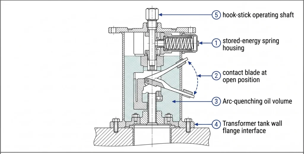
Fig. 1. Cutaway cross-section of a 40.5kV oil-immersed loadbreak switch illustrating stored-energy spring housing, contact blade travel arc, arc-quenching oil volume, and hook-stick operating shaft interface at the transformer tank wall flange.
Type T vs. Type TS: Side-by-Side Structural Comparison
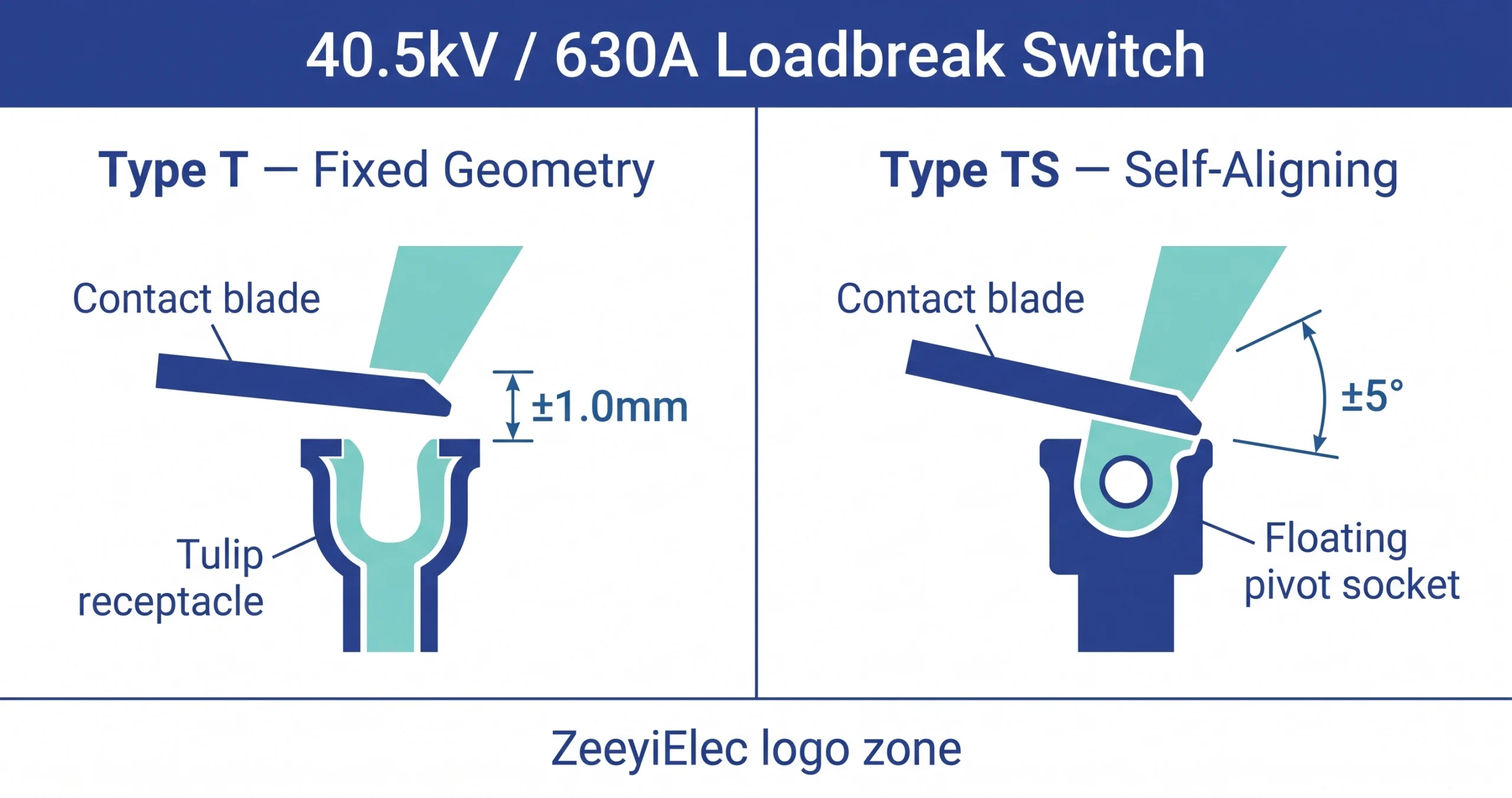
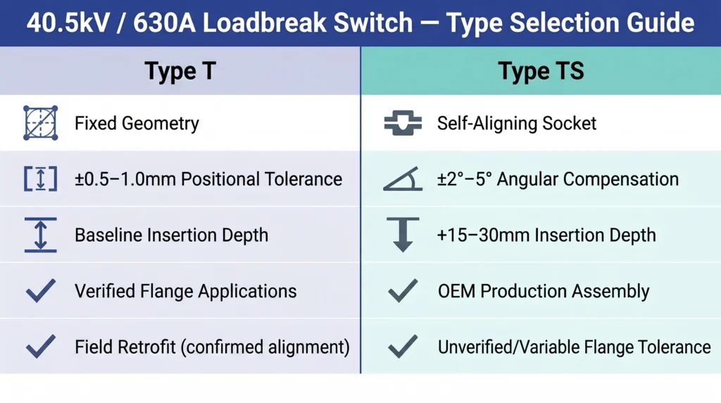
At the same 40.5kV / 630A rating, Type T and Type TS are electrically equivalent. The differentiation is entirely structural at the contact interface where the switch blade engages its mating terminal inside the transformer tank.
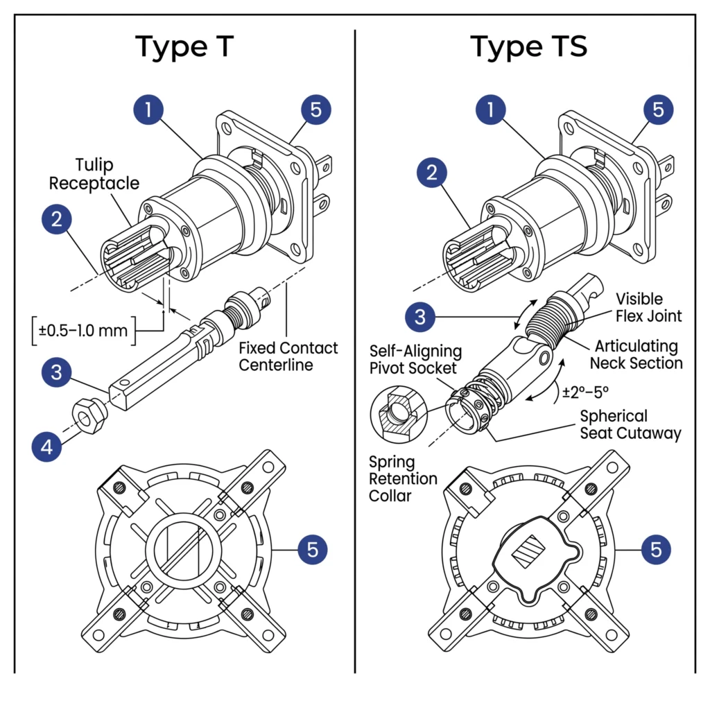
Type T uses a rigid, fixed-geometry blade assembly. Contact fingers seat correctly only when the mounting flange positions the blade centerline within ±0.5mm to ±1.0mm of true center. Any deviation beyond this range compresses contact fingers unevenly, reducing engagement area and raising junction resistance.
Type TS incorporates a self-aligning socket that pivots within ±2° to ±5° of angular offset, allowing the blade to find its seating geometry independent of minor flange misalignment. Contact force is maintained through a spring-loaded retention system within the socket rather than depending on dimensional precision of the mounting interface.
Housing, Mounting Flange, and Trip Mechanism
Type TS housings incorporate an articulating neck section immediately behind the contact socket, adding 15mm to 30mm to overall insertion depth a dimension engineers must verify against throat clearance before ordering for any retrofit application. Hook-stick pre-charge torque for both types falls in the range of 20 N·m to 45 N·m; the spring assembly is housed in the external operator section and is structurally identical between types.
Type T vs. Type TS — Structural Attribute Comparison
Structural Attribute
Type T
Type TS
Engineering Implication
Contact interface geometry
Fixed, rigid centerline
Floating self-aligning socket
TS tolerates flange stack-up; T requires precise alignment
Angular offset tolerance
±0.5mm to ±1.0mm positional
±2° to ±5° angular
TS suitable for OEM assembly variation
Insertion depth (additional)
Baseline
+15mm to +30mm
TS requires throat depth verification in retrofit
Contact force mechanism
Dimensional fit dependent
Spring-loaded socket retention
TS maintains force independent of mounting precision
Spring / trip mechanism
Stored-energy, hook-stick
Identical to Type T
No operational difference at operator interface
Electrical rating
40.5kV / 630A
40.5kV / 630A
Both types electrically equivalent
Fig. 2. Exploded comparative line drawings of Type T (fixed-geometry blade assembly, left) and Type TS (articulating neck with self-aligning pivot socket, right) 40.5kV loadbreak switches; numbered callouts indicate divergent structural components at the contact interface and mounting flange.
[Expert Insight]
The self-aligning mechanism in Type TS is not driven by spring preload alone — the structural core is a precision-engineered axial clearance of 0.05–0.10mm between the square epoxy insulating rod and the square aperture of the moving contact blade. This sub-0.1mm gap is what converts a rigid mechanical collision into a controlled, fault-tolerant seating action.
Type T’s reliability risk in volume production is systematically higher than single-unit bench testing suggests: machining tolerances, heat treatment distortion, and cumulative assembly errors stack predictably across a production batch — the larger the order quantity, the more units fall into the tail of the deviation distribution.
The square cross-section of the Type TS epoxy rod serves two simultaneous engineering functions: strict anti-rotation constraint preventing lateral blade drift during operation, and uniform force distribution across four contact faces eliminating stress concentration at the contact interface.
Contact resistance above 60µΩ per phase on a newly installed unit should trigger investigation of moving-to-stationary contact height deviation first — not default assumption of flange misalignment. The failure signatures are similar; the root causes and corrective actions are entirely different.
Self-Aligning Design in Type TS: Mechanism Physics and Engineering Rationale
The Tolerance Problem: Flange Stack-Up in Pad-Mounted Transformer Assembly
Pad-mounted transformer tanks are fabricated assemblies. Flange welding, tank wall forming, and internal terminal positioning each introduce dimensional variation. When these tolerances accumulate, the realized centerline of the mating terminal can deviate from the nominal flange centerline by 1.5mm to 4.0mm in translation, or 1° to 3° in angular offset, even within a well-controlled production environment.
For a Type T switch requiring positional accuracy within ±0.5mm to ±1.0mm, a 2.5mm stack-up deviation means asymmetric blade engagement. Effective contact area drops from a design value of 300mm² to 500mm² to a fraction of that concentrating current through a smaller cross-section and elevating junction resistance.
How the Self-Aligning Socket Compensates for Offset
The Type TS socket addresses stack-up through a two-axis compensation mechanism. A spherical or cylindrical pivot seat typically machined from bronze alloy or glass-filled polyamide — allows the socket to rotate within its retention collar. A circumferential spring array of four to six discrete elements maintains preloaded contact force against the blade regardless of angular position.
The spring preload maintains a minimum contact force of 80 N to 150 N across the full angular compensation range of ±2° to ±5°, keeping contact resistance below 50 µΩ at 630 A class even when the socket operates at the boundary of its compensation envelope. Glass-filled polyamide formulations used in the pivot seat exhibit dielectric strength of 15 kV/mm to 20 kV/mm — adequate margin when wall thickness and creepage path geometry are correctly dimensioned.
Dielectric Integrity Under Misalignment: What Changes at 40.5kV
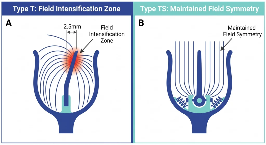
When a rigid Type T contact seats with significant offset, asymmetric blade position alters the electric field geometry around the contact tip. In oil-immersed environments, field intensification at an irregular contact edge initiates partial discharge activity below the nominal design threshold. Field observations show this degradation pathway appearing within 18 to 36 months of energization where installation misalignment went undetected at commissioning — producing failures indistinguishable from standard contact wear. Type TS preserves the symmetric field distribution the switch’s insulation coordination was designed around, eliminating this failure mode at its source.
Fig. 3. Comparative dielectric field diagrams: Panel A illustrates electric field intensification at the asymmetric contact tip of a misaligned Type T switch; Panel B shows maintained field symmetry achieved by Type TS self-aligning socket compensation under equivalent offset conditions.
Electrical and Mechanical Performance Parameters at 40.5kV Class
Shared Electrical Ratings: Where Type T and Type TS Are Equivalent
Both structural types are designed to the same switching duty requirements. Neither gains nor loses electrical capability from the self-aligning mechanism, which is confined entirely to the mechanical interface zone.
Electrical Parameter
Typical Value / Range
Notes
Rated system voltage
40.5kV
Corresponds to Um in IEC classification
Continuous current rating
630A
At ambient up to 40°C; derate above
Basic Impulse Insulation Level (BIL)
185kV or 200kV
Project spec and national grid standard govern
Rated short-circuit making capacity
12.5kA peak
Verify against upstream fault level
Rated short-time withstand current
8kA–16kA / 1s
Design-dependent; confirm with manufacturer
Power frequency withstand voltage
70kV / 1 min
Dry and wet test conditions per applicable standard
Parameters Affected by Structural Type
Contact resistance at commissioning reflects blade engagement completeness. A correctly installed Type T in a dimensionally conforming flange achieves 20µΩ to 40µΩ per phase. A unit installed with flange offset outside tolerance may measure 80µΩ to 150µΩ — generating localized heating of 15°C to 35°C above ambient at rated current, detectable by infrared thermography post-energization.
Type TS, maintaining contact force through its spring-loaded socket across ±2° to ±5° compensation range, delivers contact resistance consistently in the 25 µΩ to 50 µΩ range regardless of minor flange misalignment — eliminating the installation-condition variable from the resistance measurement.
Mechanical endurance typically 1,000 to 2,000 complete make-break operations for distribution-class switches in this voltage range is governed by the spring assembly and contact blade material, both structurally identical between types. For the authoritative switching duty classification framework, the IEC Technical Committee 17 publication on AC switches above 1kV provides foundational performance category definitions used across most national procurement specifications.
[Expert Insight]
Three application contexts should treat Type TS as the default specification rather than an upgraded option: volume procurement batches of 50 units or more; installations with difficult O&M access such as remote sites, underground switchrooms, or offshore grids; and critical load users — hospitals, data centers, rail transit systems — where a single unplanned outage carries a cost far exceeding the price delta between Type T and Type TS.
Type T retains engineering justification in small-batch, tight-delivery, or precision-controlled manufacturing programs — but only when the procurement document explicitly specifies a factory acceptance upper limit for moving-to-stationary contact height deviation, rather than relying on the supplier’s default tolerance assumption.
Model reference: FYN33-40.5-630-25-T (rigid fixed contact) and FYN33-40.5-630-25-TS (self-aligning floating contact). Both carry identical ratings — 40.5kV, 630A, 25kA rated short-circuit breaking current, Break-Before-Make (BBM) switching capability — structural divergence is confined entirely to the moving contact assembly.
If the project specification requires 200kV BIL rather than 185kV, confirm at ordering stage whether the epoxy rod wall thickness and creepage distance are upgraded consistently across both Type T and Type TS variants — do not assume the two types share identical insulation geometry at the higher BIL class.
Field Application Scenarios: When Engineers Choose Type T vs. Type TS
Scenario A: New Pad-Mounted Transformer OEM Assembly
A transformer manufacturer building pad-mounted units controls the fabrication process but cannot eliminate dimensional variation across a production run. Flange welding introduces heat distortion of 0.5mm to 2.0mm in typical steel plate construction. Across a batch of 50 to 200 units, realized flange centerline deviation follows a distribution most units fall within tolerance, a meaningful minority do not.
Specifying Type T for the entire batch means units at the tail of the dimensional distribution leave the factory with incorrectly seated switches. After tank sealing and oil-fill, the only practical detection method is infrared thermography under load a post-commissioning activity occurring weeks after the transformer leaves the factory. OEM production engineers who have encountered this pattern consistently migrate to Type TS for 40.5kV class assemblies, absorbing the per-unit cost premium to eliminate one category of warranty return.
Scenario B: Field Replacement and Retrofit into Existing Tank
Retrofit context presents a different calculation. The flange is fixed and its dimensional condition is measurable before ordering. A field engineer with access to the drained, de-energized tank can verify flange centerline position using a bore gauge or dial indicator a five-minute procedure producing a definitive answer about whether Type T positional requirements are satisfied.
If measured offset falls within ±0.5mm to ±1.0mm, Type T is acceptable and avoids the Type TS insertion depth penalty. If offset exceeds this range common in tanks where thermal cycling over 15 to 25 years has shifted weld geometry. Type TS is the correct specification regardless of the original switch type installed.
Red Flags During Commissioning
Three indicators signal incorrect specification or installation and require investigation before energization: contact resistance above 60µΩ per phase on a newly installed unit; hook-stick insertion requiring force significantly above the 20 N·m to 45 N·m pre-charge range, indicating blade binding against a misaligned receptacle; and audible or tactile irregularity during the quick-break trip sequence, suggesting the socket geometry is constraining blade travel.
Engineering Selection Guide: Decision Logic for 40.5kV Loadbreak Switch Type
Four sequential steps resolve the Type T vs. Type TS decision. Compressing this to a single judgment “Type TS is always safer” or “Type T is sufficient” routinely produces either unnecessary cost premiums or post-energization failures.
Step 1 — Confirm Voltage Class and Current Rating
Verify that the system voltage is genuinely 40.5kV class and that rated current at the switch interface does not exceed 630A continuously. For ambient temperatures above 40°C common in tropical utility installations and enclosed substation enclosures confirm the manufacturer’s derating curve. Establish required BIL at this step: if the project calls for 200kV rather than 185kV, confirm availability in both types before proceeding.
Step 2 — Assess Flange Alignment Tolerance at the Tank Interface
This is the primary Type T vs. Type TS decision gate. For new OEM production: if documented flange positional tolerance exceeds ±1.0mm, or if the manufacturer cannot provide documented tolerance, specify Type TS. For field retrofit: measure flange centerline offset directly on the drained, de-energized tank. A confirmed offset within ±0.5mm to ±1.0mm permits Type T; outside this range, specify Type TS regardless of the original switch type.
Step 3 — Identify Build Context and Verify Throat Depth
OEM production with unverifiable tolerance: default to Type TS. Field retrofit with confirmed within-tolerance measurement: Type T is acceptable and avoids the +15mm to +30mm insertion depth penalty. If retrofit throat depth is insufficient for Type TS despite alignment indication, escalate to the manufacturer for a dimensional review before ordering.
Step 4 — Cross-Check BIL and Mechanical Endurance Requirements
BIL must meet or exceed the project-specified level — 185 kV or 200 kV for 40.5 kV class systems. Mechanical endurance must satisfy expected switching frequency: distribution applications with infrequent sectionalizing operations typically require 1,000 operations minimum; loop-switching applications should specify 2,000 operations or confirm Class E2 endurance rating per the applicable switching standard.
Common Specification Errors and Field Consequences
The complete parameter verification framework including bushing interface ratings and fuse coordination at the 40.5kV level is structured in the transformer accessories selection guide.
Source 40.5kV 630A Loadbreak Switches from ZeeyiElec
ZeeyiElec manufactures loadbreak switches for distribution transformer applications across the 15kV to 40.5kV voltage range, with current ratings to 630A and configurations covering Two-Position and Four-Position sectionalizing designs in single-phase and three-phase arrangements. The portfolio supports Type T and Type TS structural variants within the 40.5kV class, allowing procurement teams to specify the correct interface geometry based on the flange alignment assessment and installation context covered in this guide.
Manufacturing is conducted at the Wenzhou, Zhejiang facility with ISO 9001 quality management processes and export documentation support including test certificates, material declarations, and shipping documentation structured for Letter of Credit compliance. OEM and ODM configurations are available for transformer manufacturers requiring dimensional customization beyond standard catalog geometry relevant for production programs where tank fabrication tolerances fall outside the range that standard offerings accommodate.
Technical response for inquiries covers model matching against project voltage class, current rating, BIL requirement, and flange interface specification. Sample availability supports dimensional verification before bulk order commitment — a practical step for retrofit procurement where throat depth confirmation is advisable before purchase order issue.
Visit the full transformer accessories product range for the complete switching device portfolio and related transformer protection components. For cable-side interface requirements on the same distribution project, the cable accessories portfolio covers termination and jointing solutions across matching voltage classes.
Fig. 4. Engineering selector card summarising key structural differentiators, angular offset tolerance, insertion depth delta, and recommended application context for Type T and Type TS 40.5kV 630A loadbreak switch variants; ZeeyiElec, 2026.
Frequently Asked Questions
What is the difference between a Type T and Type TS loadbreak switch at 40.5kV?
Type T uses a fixed-geometry contact interface requiring flange positional accuracy within ±0.5mm to ±1.0mm, while Type TS incorporates a self-aligning socket accommodating angular offset of ±2° to ±5°, making it better suited for pad-mounted transformer assemblies where dimensional stack-up during fabrication is unavoidable.
What does self-aligning mean in a loadbreak switch design?
Self-aligning refers to a floating socket interface a spring-loaded pivot seat in bronze alloy or glass-filled polyamide that compensates for minor positional or angular offset between the switch blade and its mating terminal, maintaining adequate contact force and dielectric integrity without requiring exact mechanical alignment.
Is a 40.5kV 630A loadbreak switch suitable for three-phase pad-mounted transformers?
A 630A continuous rating covers most distribution-class pad-mounted transformers at the 40.5kV system voltage class, but suitability depends on the transformer’s rated current, upstream fault level for making capacity verification, and whether ambient temperature inside the enclosure requires derating below the nameplate current.
What BIL rating should a 40.5kV class loadbreak switch carry?
The 40.5kV system voltage class typically requires 185kV or 200kV BIL depending on the applicable national grid standard; engineers should confirm the required level from the transformer nameplate or project technical document before issuing a purchase order.
Can a Type T loadbreak switch replace a Type TS in a field retrofit application?
Type T is acceptable in a retrofit application if the existing flange is confirmed within ±0.5mm to ±1.0mm of nominal centerline by direct measurement on the drained, de-energized tank; substituting Type T for Type TS without this verification risks elevated contact resistance and switching failure under load.
How many mechanical operations should a 40.5kV loadbreak switch be rated for?
Distribution-class switches at 40.5kV are typically rated for 1,000 to 2,000 complete make-break operations, with the higher endurance class appropriate for loop-switching duty where operation frequency significantly exceeds standard sectionalizing applications.
What contact resistance value indicates a correctly seated 630A loadbreak switch at commissioning?
A contact resistance below 50µΩ per phase is a generally accepted commissioning acceptance threshold for 630A-class switches; readings above this range warrant investigation of blade seating, flange alignment, and contact surface condition before energization.
yoyo shi
Yoyo Shi writes for ZeeyiElec, focusing on medium-voltage accessories, transformer components, and cable accessory solutions. Her articles cover product applications, technical basics, and sourcing insights for global electrical industry buyers.