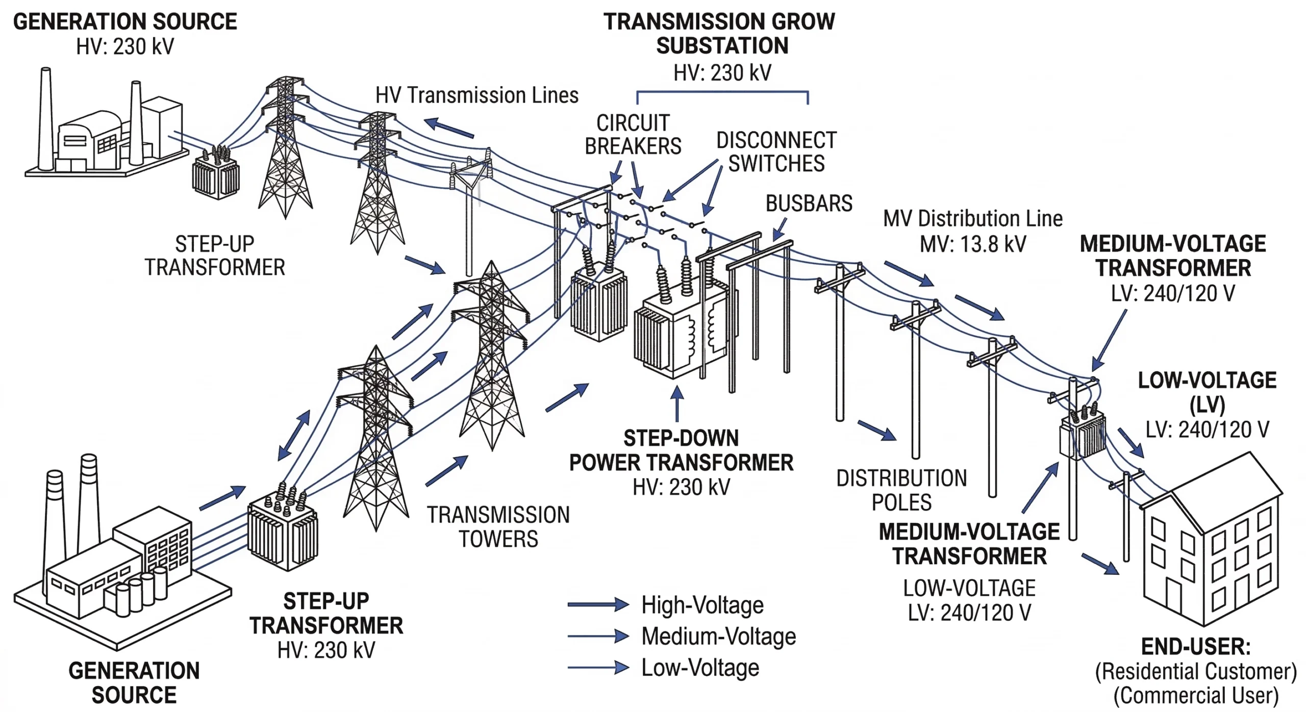
A medium-voltage (MV) transformer is a specialized piece of electrical equipment designed to step down high transmission voltages to safer, usable distribution levels. Operating primarily within the 11 kV to 35 kV voltage range, these transformers rely on electromagnetic induction to transfer power between utility grids and industrial, commercial, or residential load centers.
Figure 01:A standard electrical distribution topology illustrating the essential position of a medium-voltage transformer stepping down power for localized consumption.
The Physics of Voltage Transformation
At its core, a medium-voltage transformer operates on Faraday’s law of induction. Power enters the primary winding—typically constructed from tightly wound copper or aluminum conductors—creating an alternating magnetic flux. This flux travels through a high-permeability, laminated silicon steel core and intersects the secondary winding. The ratio of turns between the primary and secondary windings dictates the exact voltage step-down. For example, a common industrial unit might step down a 33 kV primary feed to a 415 V secondary output, supporting power ratings anywhere from 500 kVA up to 10 MVA depending on the facility’s demand.
Managing Dielectric Stress
Voltages between 11 kV and 35 kV generate significant electrical stress. At these levels, standard air clearances are insufficient for compact equipment footprints. Consequently, the internal active parts (core and windings) must be encapsulated in a high-grade dielectric medium. In liquid-filled designs, highly refined mineral oil or synthetic ester fluids are used to simultaneously insulate the conductors and dissipate the thermal energy generated by electrical losses. Conversely, dry-type transformers utilize vacuum-cast epoxy resins to achieve the same dielectric integrity without the use of combustible fluids, making them standard for indoor installations.
Interfaces and Connections
Because the active core is heavily insulated and sealed within a grounded steel tank, transferring the 11 kV to 35 kV current into and out of the enclosure requires specialized hardware. The main unit relies heavily on to function safely. These critical interface components support insulated connection, fault protection, switching operations, and voltage adjustment in distribution transformer systems. Insulated bushings bridge the grounded tank wall, while off-circuit tap changers and protection fuses ensure the core remains shielded from external grid transients. Without these precision-engineered interfaces, the transformer cannot be safely energized or connected to the wider distribution network.
Structural Components and Internal Physics
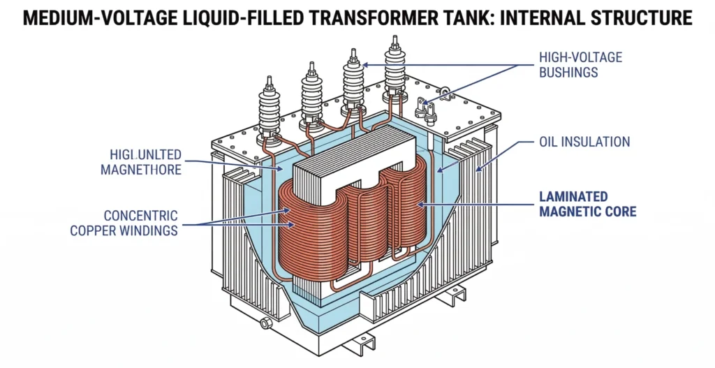
Figure 02:Internal architecture of a liquid-immersed medium-voltage transformer, highlighting the highly permeable silicon steel core, conductive windings, and insulating dielectric fluid.
To understand how medium-voltage transformers safely handle substantial electrical loads, it is necessary to examine their internal architecture. The core structural components are engineered to simultaneously manage high-voltage magnetic flux, extreme thermal outputs, and severe dielectric stress.
Magnetic Core and Windings
The active part of the transformer consists of the central magnetic core and the concentric conductive windings. The core is constructed from highly permeable, cold-rolled grain-oriented (CRGO) silicon steel laminations. These laminations, typically manufactured to precise thicknesses between 0.23 mm and 0.30 mm, are stacked tightly to form a low-reluctance path for the magnetic flux while minimizing unwanted eddy currents.
Surrounding the steel core legs are the primary and secondary windings, usually wound from high-conductivity electrolytic copper or aluminum. The fundamental efficiency of this active assembly relies on minimizing I2R losses (copper losses) and hysteresis, ensuring the unit maintains a maximum winding temperature rise of typically ≤ 65°C under full continuous load conditions.
Dielectric Insulation Systems (Oil vs. Dry-Type)
Because the internal conductors carry voltages from 11 kV up to 35 kV, preventing phase-to-phase and phase-to-ground electrical arcing is paramount. The International Electrotechnical Commission (IEC) develops standards defining minimum performance requirements, test methods, and acceptance criteria for these high-voltage systems.
In liquid-immersed transformers, the entire core and coil assembly is submerged in highly refined mineral oil or synthetic ester fluids. This dielectric fluid penetrates the specialized kraft paper wrapped around the winding conductors, providing exceptional insulation strength while circulating via natural or forced convection to dissipate heat. Conversely, dry-type alternatives replace the liquid medium with cast epoxy resin. The windings are encapsulated under vacuum, creating a solid dielectric barrier that is self-extinguishing and free of fluid leakage risks, though they generally require a larger physical footprint to achieve comparable cooling.
Critical Accessory Interfaces (Bushings & Tap Changers)
A transformer’s internal components are heavily isolated within a grounded steel tank, necessitating engineered interfaces to connect with the external grid safely. function as critical insulated pass-through components installed on the transformer tank wall to safely transfer current between internal windings and external circuits. In practical applications, these bushings are selected by standard systems and rated for voltage classes from 12kV up to 52kV.
External grid voltages are rarely perfectly stable. To compensate for minor voltage fluctuations on the distribution network, transformers incorporate an off-circuit tap changer. This mechanical switching device is used to adjust the transformer turns ratio, strictly operating only when the unit is de-energized. Together, these structural and interface components define the transformer’s operational boundaries and long-term reliability.
[Expert Insight]
Dielectric Fluid Testing: Always mandate dissolved gas analysis (DGA) for oil-filled units before commissioning; establishing baseline data is critical for future fault diagnosis.
Bushing Specification: Over-specifying bushing creepage distance by 10–15% is a low-cost insurance policy against unexpected site contamination or salt spray.
Epoxy Cast Curing: For dry-type transformers, verify the manufacturer’s vacuum casting process documentation to ensure zero void formation in the resin, which prevents partial discharge.
Voltage Classifications and Selection Logic
Selecting the correct medium-voltage transformer requires mapping the facility’s power demand and grid infrastructure to standardized voltage classes. The chosen voltage class dictates not only the internal winding design but also the required dielectric strength, spatial clearances, and the exact specifications for the connecting components.
Voltage Class Application Mapping
The 11 kV / 15 kV Distribution Class
The 11 kV and 15 kV systems represent the backbone of standard commercial and urban distribution. Transformers in this category are designed to balance compact footprints with reliable power delivery. Because these units are frequently installed in confined indoor switchgear rooms or underground vaults, field engineers prioritize installation safety and spatial efficiency. In such restricted environments, connection points are typically sealed using , which are pre-expanded silicone insulation components used for medium-voltage cable terminations and joints. These allow for secure, flame-free installations where traditional open-flame techniques would pose a severe fire hazard.
The 33 kV / 35 kV Sub-Transmission Class
Moving up to the 33 kV and 35 kV classes shifts the engineering focus toward managing significantly higher dielectric stress and environmental exposure. These transformers serve as critical nodes in heavy industrial facilities or renewable energy collector substations, bridging the gap between high-voltage transmission and localized distribution.
Equipment in this tier must withstand severe transient overvoltages, often requiring a BIL of 150 kV or 200 kV according to IEEE C57.12.00. Furthermore, 35 kV class transformers demand strict phase-to-phase and phase-to-ground clearances, typically mandating spatial gaps of ≥ 350 mm in air to prevent catastrophic arc flashes.
Consequently, the protective accessories matching this voltage tier must be rigorously specified to maintain systemic insulation integrity under heavy load cycles. Mismatches between accessory characteristics—such as dielectric strength and thermal capacity—account for a significant portion of system failures.
Field Conditions and Environmental Variables
A transformer’s theoretical lifespan relies heavily on mitigating harsh field conditions. Once deployed in a distribution network, these units face constant environmental stressors that accelerate insulation degradation and mechanical wear. Understanding these variables is critical for long-term grid reliability and accurate specification.
Temperature Rise and Cooling Mechanisms
Thermal management fundamentally dictates a transformer’s operational longevity. During peak load cycles in ambient environments exceeding 40°C, the internal winding ΔT (temperature rise) can easily surpass the standard 65°C design limit. Field experience consistently demonstrates that for every 8°C the operating temperature rises above its nameplate thermal rating, the internal paper insulation life is effectively halved. While external radiator fins and cooling fans mitigate this heat, field engineers frequently encounter nuisance tripping or accelerated thermal aging caused simply by blocked airflow in poorly ventilated indoor vaults.
Altitude and Dielectric Derating Constraints
Installations in high-altitude regions, such as mining operations situated above 1,000 meters, face unique challenges due to reduced air density. Thinner air diminishes both the dielectric strength of external clearances and the convective cooling efficiency of the transformer tank. According to standard engineering guidelines per IEC 60076-2 standards, equipment operating above this threshold requires a dielectric derating of approximately 1 percent per 100 meters of elevation. To compensate, field deployment in these rarified atmospheres requires specifying higher basic impulse levels (BIL) and larger bushing creepage distances.
Contamination and Moisture Ingress Realities
In coastal, agricultural, or heavily industrialized zones, salt spray and conductive dust settle on exposed terminals, leading to surface tracking and eventual phase-to-ground faults. To combat this at the critical cable interfaces, installation crews often utilize heat shrink cable accessories to create a weather-tight, anti-tracking seal over the medium-voltage connections.
Furthermore, moisture ingress is particularly lethal to liquid-filled units. If the water content in the insulating mineral oil reaches ≥ 30 ppm (parts per million), the internal dielectric strength plummets. This microscopic water contamination drastically reduces the flashpoint and increases the risk of an internal short circuit.
[Expert Insight]
Ventilation Calculations: Never rely solely on passive louvers for indoor 35 kV vaults; always calculate forced-air CFM requirements based on maximum load thermal dissipation.
Altitude Corrections: If your site exceeds 1,000 meters, explicitly state the elevation in your RFQ so the factory can properly adjust the basic impulse level (BIL) and external clearances.
Moisture Defense: In areas with heavy rainfall or coastal humidity, specify hermetically sealed tanks or ensure free-breathing units are equipped with oversized silica gel breathers.
Common Failure Modes and Accessory Protection
Medium-voltage transformers rarely fail in isolation; catastrophic breakdowns are typically the result of external grid anomalies exceeding the core’s mechanical and thermal limits. To prevent a localized field failure from cascading into a substation outage, transformers rely on a coordinated suite of protective accessories designed to isolate faults and manage switching arcs.
A primary failure mode involves severe short circuits that subject the transformer windings to massive electromechanical forces. To mitigate this, engineers deploy engineered for rapid fault-current cutoff, high interrupting capability, and reliable coordination in distribution transformer protection schemes.
During a bolted fault, currents spike to thousands or tens of thousands of amperes within milliseconds, occasionally reaching 50,000 amperes or more. The fuse operates by melting its internal silver elements and introducing a high-resistance arc, effectively forcing the current to zero within a half-cycle. This rapid interruption severely limits the destructive I2t let-through energy, preventing the internal insulation from exceeding its maximum ΔT thresholds and shielding the core from mechanical deformation.
Safe Switching and Load Management (Loadbreak Switches)
Another critical failure pathway involves improper field switching operations. Field crews sometimes confuse switching devices, and operating an off-circuit tap changer under load damages contacts and risks internal transformer faults. To safely manage energized networks, transformers utilize a dedicated loadbreak switch engineered for reliable switching in oil-immersed systems.
Unlike off-circuit devices, a loadbreak switch interrupts current while the transformer stays energized. These devices are typically rated for 630 A continuous current across 15/25 kV and 38/40.5 kV voltage classes. By utilizing specialized arc-quenching materials and spring-loaded quick-make/quick-break mechanisms, they ensure that field personnel can safely isolate transformer loads without generating sustained electrical arcs that could vaporize the surrounding dielectric oil.
Specifying Transformers and Critical Accessories for Your Project
Specifying a medium-voltage transformer for your distribution network extends far beyond selecting a base kVA rating. Whether you are engineering a compact 15 kV commercial pad-mounted unit or a massive 35 kV renewable energy collector substation, long-term system reliability depends entirely on strict accessory compatibility. The active core and windings dictate the theoretical power capacity, but the external protective and connection interfaces dictate real-world operational safety.
Procurement and field engineers must verify that every individual component matches the exact system voltage and fault current parameters. For instance, selecting a 200 A continuous bushing well or a robust 630 A loadbreak switch requires cross-referencing basic impulse levels (BIL) and thermal limits to ensure the accessories can withstand the specific network’s transient overvoltages. A simple mismatch in dimensional tolerances or dielectric strength between the transformer tank and the connecting can lead to accelerated partial discharge and premature failure at the interface.
At ZeeyiElec, our engineering team bridges this specification gap. We provide a complete, technically verified ecosystem of transformer and cable accessories engineered to integrate seamlessly into your 11 kV to 35 kV distribution projects. Share your project drawings and environmental requirements with our team to receive precise model matching, export documentation support, and a comprehensive RFQ response tailored to your exact distribution parameters.
What is the lifespan of a medium-voltage transformer?
A typical medium-voltage transformer operates reliably for 25 to 30 years under normal environmental baseline conditions and standard 80 percent load cycles. However, sustained thermal overloading or neglected maintenance can prematurely degrade the internal paper insulation, effectively reducing this projected service life by up to 50 percent.
Can an 11 kV transformer handle 33 kV inputs?
No, an 11 kV transformer is engineered with highly specific dielectric insulation thresholds and clearance distances designed exclusively for an 11 kV or 15 kV maximum continuous system voltage. Applying a 33 kV feed to these primary terminals will instantly overcome the dielectric rating, causing immediate electrical flashover and catastrophic equipment failure.
What is the difference between dry-type and oil-filled MV transformers?
Oil-filled transformers utilize highly refined mineral or synthetic ester fluid for both active core cooling and internal dielectric insulation, making them highly efficient for exposed outdoor distribution substations. Conversely, dry-type transformers rely entirely on vacuum-cast epoxy resin or solid insulation systems and are typically mandated for confined indoor commercial applications due to strict fire safety regulations.
How much clearance is required around a 35 kV transformer?
Standard high-voltage safety protocols generally dictate a minimum spatial clearance ranging from 3 to 10 feet around the unit, depending on whether the perimeter serves as operational working space or a fire barrier. Because physical separation is critical for arc flash safety, field engineers must always consult local electrical codes and the manufacturer’s specific dimensional datasheets.
Why do medium-voltage transformers hum?
The characteristic humming noise occurs when the alternating magnetic field causes the silicon steel core laminations to microscopically expand and contract 100 to 120 times per second based on grid frequency. While this low-frequency baseline hum is a normal operational trait, sudden excessive rattling often indicates mechanical loosening of the core bolts that requires immediate diagnostic maintenance.
How often should a medium-voltage transformer be tested?
Routine visual inspections and thermographic scanning should be conducted monthly to identify surface hot spots, while comprehensive dielectric fluid analysis and heavy electrical testing typically occur every 12 to 36 months. Installations situated in high-humidity regions, heavy-load industrial plants, or coastal salt-spray environments generally require more aggressive, annual testing schedules to prevent insulation failure.
yoyo shi
Yoyo Shi writes for ZeeyiElec, focusing on medium-voltage accessories, transformer components, and cable accessory solutions. Her articles cover product applications, technical basics, and sourcing insights for global electrical industry buyers.