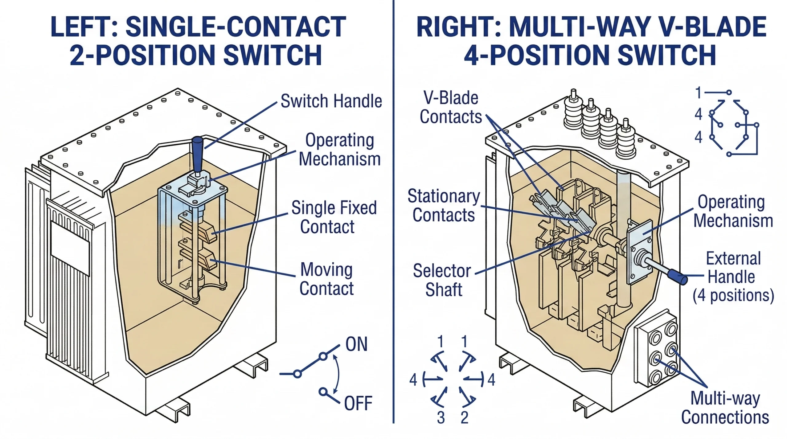
Figure 01:Comparative schematic showing the single contact path of a 2-position isolator versus the multi-directional routing capabilities of a 4-position switch.
A loadbreak switch is a critical mechanical switching device mounted inside or on the tank wall of a distribution transformer. Unlike off-circuit tap changers, which must only be operated when the transformer is completely de-energized, loadbreak switches are engineered to safely make or break rated continuous current while the system remains fully energized. This capability is essential for isolating sections of a medium-voltage network during maintenance or fault conditions without dropping the entire feeder line.
For utility distribution networks, these switches are typically deployed in oil-immersed, pad-mounted transformers operating within the 15/25 kV to 35 kV voltage classes.
Standard switch designs are generally rated to safely interrupt continuous currents ≤ 630 A, utilizing a spring-loaded, stored-energy mechanism.
This “quick-make, quick-break” action ensures that the contact separation speed is entirely independent of the human operator’s physical hook-stick movement. Rapid separation is a physical necessity; as the contacts part, the surrounding dielectric fluid (mineral oil or natural ester) must immediately rush into the expanding gap to cool and extinguish the electrical arc before it can destabilize the system or degrade the contacts.
The Functional Divide: 2-Position vs. 4-Position
The foundational difference between a 2-position and a 4-position lies in their internal contact architecture and intended network topology.
2-Position Switches: Function as a straightforward isolator. They feature a single set of movable contacts providing a binary operational state: On (closed) or Off (open). This mechanical simplicity makes them the standard, cost-effective choice for radial feed distribution lines where power flows from the source to the load in only one direction.
4-Position Switches: Serve as complex routing hubs for loop feed systems. They incorporate multiple contact configurations to manage two incoming high-voltage lines alongside the transformer’s own primary winding. This architecture allows field operators to select between four distinct states, facilitating multi-directional power flow and localized isolation without interrupting the broader loop.
The mechanical endurance and arc-quenching capabilities of these devices are rigorously tested. [VERIFY STANDARD: IEEE Std C37.74 defines the design and testing requirements for load-interrupting switches applied in pad-mounted enclosures up to 38 kV, stipulating minimum mechanical operations and fault-closing capabilities.] [NEED AUTHORITY LINK SOURCE: IEEE Std C37.74 standard page].
[Expert Insight]
Specifying a switch goes beyond just the electrical rating; physical tank dimensions dictate feasibility. A 4-position switch requires a significantly larger operational envelope within the dielectric fluid.
Attempting to retrofit a 2-position transformer tank with a 4-position switch in the field is almost universally rejected due to insufficient phase-to-ground clearances and inadequate oil volume.
The Mechanics of 2-Position Loadbreak Switches
A 2-position switch is the most fundamental switching configuration among transformer accessories engineered for distribution networks. It operates purely as a two-state device: open (de-energized) or closed (energized). Designed for integration into both 1-phase and 3-phase oil-filled pad-mounted transformers, these components are frequently specified for 15/25 kV and 38/40.5 kV voltage classes.
Contact Architecture and Arc Extinction
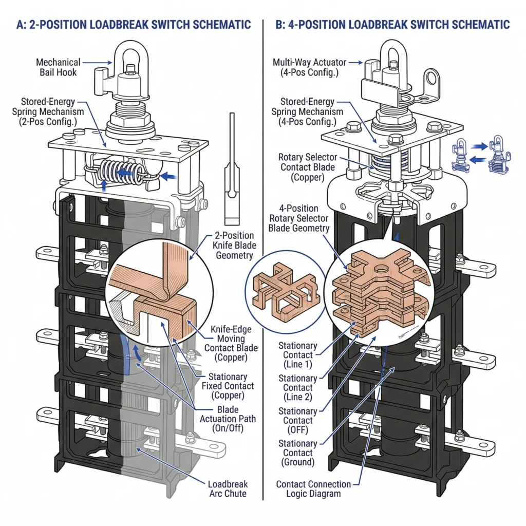
The physical construction of a 2-position loadbreak switch centers around a hook-stick operable mechanism.
To maintain thermal stability and prevent localized heating, the internal contact resistance must typically remain ≤ 50 μΩ during continuous 630 A current flow.
When an operator initiates a state change using a hot stick, they are actually charging a heavy-duty internal torsion spring. Once the spring compresses past its mechanical dead-center, it releases its stored energy instantly. This forces the moving copper contacts to separate from the stationary contacts at a precisely calibrated, high velocity. From a field perspective, this quick-break action is critical: it physically removes human error from the equation. Even if a lineman pulls the external handle slowly, the internal blades snap open rapidly, elongating the electrical arc so the surrounding dielectric oil can immediately quench it before the fluid suffers excessive carbon contamination.
Radial Feed Deployment Scenarios
The 2-position switch is the standard, economical choice for radial feed distribution networks. In a radial topology, power flows in a single, one-way path from the utility substation to the end-user load. There is no alternative power routing available.
When a pad-mounted transformer sits at the end of a radial line—or serves an isolated commercial tap—the 2-position switch functions perfectly as a local point of isolation. If a maintenance crew needs to service the transformer or replace a downstream component, they simply rotate the switch to the “Off” state. This safely interrupts the rated current and isolates the equipment without forcing the utility to drop the entire upstream feeder line. Because it requires fewer internal contacts and moving parts, the 2-position design occupies less physical space inside the transformer tank and introduces fewer potential mechanical failure points over a 30-year operational lifespan.
4-Position Loadbreak Switches: Routing in Loop Systems
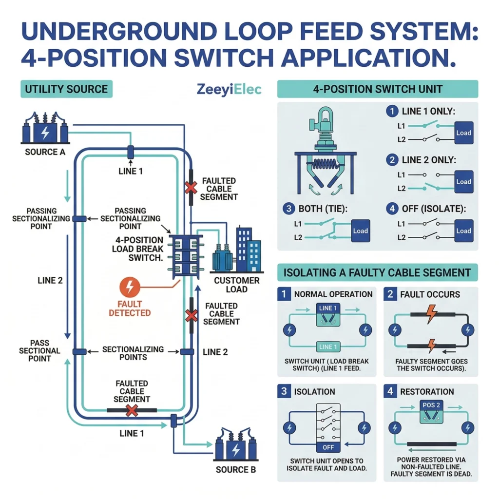
Figure 02:Power flow routing options in an underground loop feed distribution network utilizing a four-position sectionalizing loadbreak switch.
While radial networks rely on single-path power delivery, modern underground distribution grids frequently employ loop feed architectures to improve system reliability. In these networks, a pad-mounted transformer is connected to two independent power sources. To manage this bidirectional power flow without dropping the load, engineers specify a four-position sectionalizing switch. This design acts as a miniature routing hub inside the transformer tank, engineered for switching under load.
V-Blade vs. T-Blade Configurations
The internal architecture of a four-position switch is dictated by the shape of its moving contact blades, typically categorized into V-blade and T-blade configurations. A V-blade switch connects two incoming line feeds directly to a common center point tied to the transformer’s primary windings. Conversely, a T-blade configuration allows the two incoming lines to be connected to each other while simultaneously feeding the transformer tap.
Regardless of the internal blade geometry, these sectionalizing switches are heavily engineered components designed to handle high electrical stress, typically carrying a continuous current rating of Icontinuous = 630 A across 15/25 kV and 38/40.5 kV voltage classes.
This mechanical robustness ensures that the switch can continuously carry the full loop current passing through the equipment, rather than just handling the localized load of that specific transformer.
Maintenance and Sectionalizing Advantages
The defining field advantage of a four-position switch is its ability to transition between four distinct operational states: Line 1, Line 2, Both (Loop Closed), and Off (Open).
From a field operation perspective, this flexibility is invaluable during underground cable faults or routine maintenance. If a fault occurs in the cable run between two pad-mounted transformers, a utility crew can use their hot sticks to open the specific switch contacts feeding the damaged section. This securely isolates the fault while allowing the transformer to remain energized from the alternate, healthy line feed. Because these switches manage the connections for high-voltage underground cables—which are terminated using critical to manage stress fields and environmental protection—the ability to isolate specific cable segments safely without de-energizing entire neighborhoods is a primary driver for their widespread adoption in commercial and residential loop layouts.
Direct Comparison: 2-Position vs. 4-Position Decision Matrix
Selecting the correct loadbreak switch requires engineers to balance grid architecture against mechanical complexity, tank space, and project budgets. Both configurations must pass rigorous mechanical endurance and load-interrupting tests, but their application boundaries are distinctly different.
The following decision matrix outlines the core differences for quick technical evaluation during the procurement phase:
Operational Complexity and Training
From a field perspective, the operational complexity scales significantly with the 4-position design. Operating a 2-position switch is a straightforward isolation task. Conversely, linemen operating a 4-position switch must follow strict, written switching orders. Moving the mechanism to the wrong position in an energized loop can inadvertently parallel out-of-phase circuits or drop critical downstream loads.
Mechanically, both switch types rely on stored-energy springs where the operating torque typically ranges from 120 N×m to 150 N×m.
This requires a firm, continuous pull with a standard insulated hot stick to charge the spring past its dead-center release point, ensuring the quick-break mechanism triggers correctly regardless of operator speed.
Space and Cost Implications for Pad-Mounted Transformers
The internal footprint of the switch directly dictates the physical dimensions of the transformer tank. Because it routes multiple high-voltage paths, a 4-position switch requires a significantly larger phase-to-phase and phase-to-ground isolation zone within the dielectric fluid.
To safely manage transient recovery voltages and prevent internal arcing, the 4-position mechanism often demands ≥ 150 mm of additional clearance inside the oil tank compared to a simple 2-position setup.
This increased footprint means the transformer requires more steel for the tank and a higher volume of insulating oil, driving up the total unit cost. Furthermore, the expanded switch footprint must be carefully coordinated with other internal components, such as the and core-and-coil assembly, to ensure thermal dissipation paths remain unobstructed during peak loading conditions.
[Expert Insight]
Frequent load breaking under high current accelerates contact wear and deposits carbon in the dielectric fluid. Oil dissolved gas analysis (DGA) should be performed regularly on heavily cycled loop-feed transformers.
Never use a loadbreak switch to attempt to clear a bolted fault; they are rated for load interruption, whereas fault clearing is strictly the domain of current limiting fuses or upstream reclosers.
Engineering Field Guide for Switch Selection
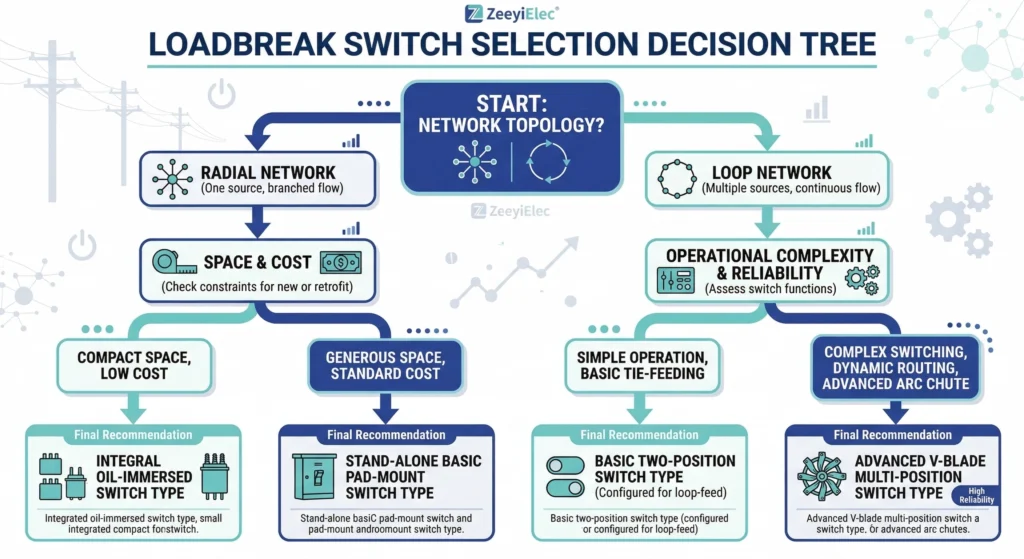
Figure 03:Engineering selection framework for choosing between radial 2-position and loop-feed 4-position loadbreak switches based on grid architecture.
Specifying the correct transformer switching configuration requires moving beyond baseline electrical parameters and evaluating the physical realities of the deployment site. While both two-position and four-position sectionalizing designs are available with stored-energy quick action mechanisms, the optimal choice hinges on a combination of immediate grid architecture and long-term utility planning.
Step 1: Mapping Current and Future Network Topology
The primary driver for switch selection is the network’s feed configuration. If a 1-phase or 3-phase oil-filled transformer is being installed at the absolute end of a rural distribution line or a dedicated industrial spur, a 2-position switch is the financially and mechanically correct choice. However, engineering foresight is critical. If urban planners intend to develop an adjacent subdivision within the next decade, specifying a 4-position switch during the initial transformer procurement allows the utility to seamlessly integrate the unit into a future loop feed without replacing the entire transformer tank.
Even if the immediate local load only draws 45 A on a 15/25 kV system, a 4-position switch rated for a full continuous current of Ic = 630 A ensures the internal contacts can safely carry the combined loop current once the circuit is tied together.
Step 2: Evaluating Local Switching Safety Protocols
Field operations dictate how equipment will actually perform over its operational lifecycle. Both switch types feature hook-stick operable mechanisms, but their operational risks differ. A 2-position switch presents a simple binary choice for a lineman working in difficult environmental conditions. A 4-position switch, while offering superior routing flexibility, requires strict adherence to switching orders to avoid dropping critical loads or inadvertently paralleling unsynchronized power sources.
Furthermore, the switch must coordinate physically and electrically with other protective devices. [VERIFY STANDARD: IEEE Std C57.12.34 establishes the performance requirements for pad-mounted, compartmentalized transformers, detailing how loadbreak switches must safely integrate alongside high-voltage protection.] During a fault sequence, the switch is primarily used for isolation only after primary protection elements, such as , have successfully cleared the high-magnitude fault current. Proper selection ensures that field crews can confidently sectionalize the grid, restore power to healthy segments, and maintain system integrity under duress.
Sourcing Reliable Transformer Switching Solutions
Selecting the appropriate switching mechanism is only the first step in ensuring grid reliability; sourcing components that consistently meet physical and electrical tolerances over a multi-decade lifespan is equally critical. ZeeyiElec provides engineered loadbreak switch solutions designed specifically for 1-phase and 3-phase oil-filled distribution transformers. Whether your project requires a straightforward 2-position mechanism for an isolated radial feed or a complex 4-position sectionalizing switch to manage a bidirectional loop network, component durability directly dictates system uptime.
Our loadbreak mechanisms are rigorously engineered to handle a continuous current rating of 630 A across standard 15/25 kV and 38/40.5 kV voltage classes. To ensure long-term mechanical reliability, the stored-energy springs and copper contacts are designed to maintain operational integrity through ≥ 500 load-interrupting cycles without severe dielectric oil degradation.
As a dedicated manufacturer of based in Wenzhou, China’s electrical manufacturing hub, we prioritize technical transparency and structural consistency. We support utility procurement teams, EPC contractors, and transformer OEMs with precise technical selection guidance, rapid engineering response times, and complete export documentation packages. This comprehensive approach ensures that the selected switch complies with the rigorous safety protocols demanded by modern distribution networks. By aligning procurement directly with an engineering-oriented supplier, projects avoid the costly delays associated with specification mismatches and premature field failures.
Frequently Asked Questions
Can a 2-position switch be upgraded to a 4-position switch later?
Most pad-mounted transformers are manufactured with specific tank cutouts and phase-to-ground clearances, making field upgrades from 2-position to 4-position switches highly impractical. Engineers must specify the correct switch configuration during the initial procurement phase, as multi-way mechanisms often require significantly more internal space and dielectric oil volume to function safely.
What does a “V-blade” configuration mean in a 4-position switch?
A V-blade 4-position switch connects two incoming line feeds to a common center tap linked to the transformer coils, allowing independent isolation of either line while keeping the transformer energized. This specific blade geometry is standard for maintaining continuous service during localized cable repairs in underground loop feed distribution systems.
Are 4-position loadbreak switches only used in pad-mounted transformers?
While 4-position switches are predominantly installed in oil-filled, pad-mounted distribution transformers for 15/25 kV underground loop networks, they can also be found in certain submersible and vault-type transformers. Their deployment depends entirely on the engineering requirement for multi-directional power routing rather than the physical mounting style of the enclosure.
How many operations is a standard loadbreak switch rated for?
Standard medium-voltage loadbreak switches are typically rated for up to 500 mechanical no-load operations, but full load-interrupting operations at ≤ 630 A are strictly limited to fewer cycles based on manufacturer contact wear curves. Continuous maintenance records must be kept to ensure the spring-loaded quick-break mechanism remains within its safe operational lifespan.
What is the primary cause of loadbreak switch failure in the field?
Field failures most commonly result from operators switching the mechanism improperly or from degraded insulating fluid, which draws an extended electrical arc that pits the copper contacts. Modern switches employ stored-energy springs to mitigate human error, but proper hot-stick operation remains critical for maintaining the required ≤ 50 μΩ contact resistance over time. [HTML-BLOCK-END]
Can I use a loadbreak switch to regulate transformer voltage?
No, a loadbreak switch is strictly designed to safely interrupt or route continuous current and cannot change the internal voltage ratio of the core-and-coil assembly. Voltage adjustment requires a completely different component—an off-circuit tap changer—which must only be operated when the distribution transformer is completely de-energized and isolated from the grid.
yoyo shi
Yoyo Shi writes for ZeeyiElec, focusing on medium-voltage accessories, transformer components, and cable accessory solutions. Her articles cover product applications, technical basics, and sourcing insights for global electrical industry buyers.