What is a transformer accessory system? A transformer accessory system is the integrated set of components — bushings, fuses, switches, and tap changers — that form the interface layer between a distribution transformer’s internal windings and the external power network, performing insulated current transfer, fault interruption, switching, and voltage ratio adjustment as an interdependent system.
Distribution transformer engineering typically focuses on core and winding design — the magnetic circuit, conductor cross-section, and insulation grade. Accessories receive less attention during specification, yet they determine whether the transformer connects reliably to the network, responds correctly to fault events, and survives the service environment. Understanding transformer accessories as a system, rather than a parts list, is the prerequisite for sound distribution project engineering.
What Is a Transformer Accessory System?
A transformer accessory system is the integrated set of components that form the interface layer between a transformer’s internal windings and the external power network. This layer performs four distinct functions: insulated current transfer (bushings and bushing well inserts), fault detection and interruption (fuse assemblies), switching and isolation (loadbreak switches), and voltage ratio adjustment (tap changers). The components do not operate independently — their electrical and mechanical parameters must align across the entire system.
Defining the System Boundary
The accessory system boundary begins at the transformer tank wall, where internal winding connections meet external mounting interfaces, and extends to the point of network connection. Within this boundary, every component carries a voltage class designation, a current rating, and a basic impulse insulation level (BIL). For a typical 15 kV distribution transformer, BIL values for accessories commonly range from 95 kV to 150 kV depending on component type and system exposure. These parameters must be consistent across all accessories on the same transformer — a mismatch at any interface point creates a dielectric weak link that field experience consistently identifies as a commissioning or early-service failure site.
Why Architecture Thinking Changes Specification Practice
Treating accessories as a system changes how procurement specifications are written. A bushing well insert is not simply a hardware item — it defines the separable connector interface geometry and voltage class that the mating MV bushing must match. A Bay-O-Net fuse assembly is not simply a protection device — its interrupting current range determines what the current limiting fuse must cover above that threshold. Each component selection constrains or enables adjacent selections, which is why accessory mismatches account for a measurable share of distribution transformer commissioning delays.
Specifying accessories layer by layer — insulation, protection, switching, regulation — rather than component by component reduces specification gaps before they reach the field. The full product scope covering these functional layers is documented in ZeeyiElec’s transformer accessories range, which spans bushings, fuse assemblies, switches, and tap changers for distribution voltage classes.
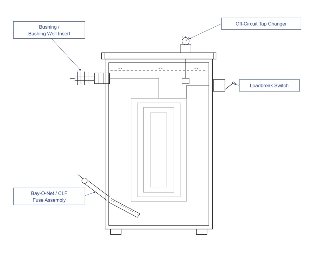
Cross-sectional elevation of a distribution transformer tank identifying the four primary accessory zones — bushing/bushing well insert, Bay-O-Net/CLF fuse, loadbreak switch, and tap changer — at their respective mounting positions (ZeeyiElec, 2026).
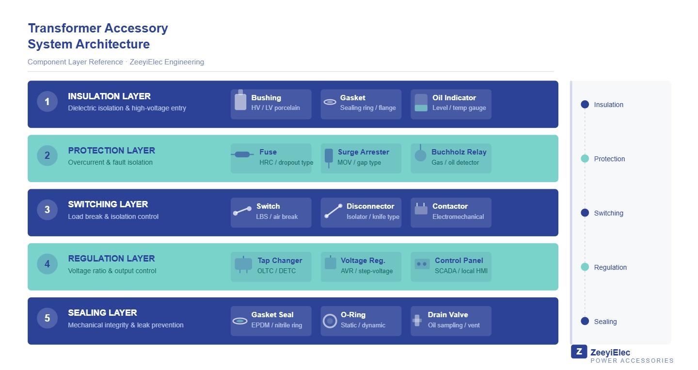
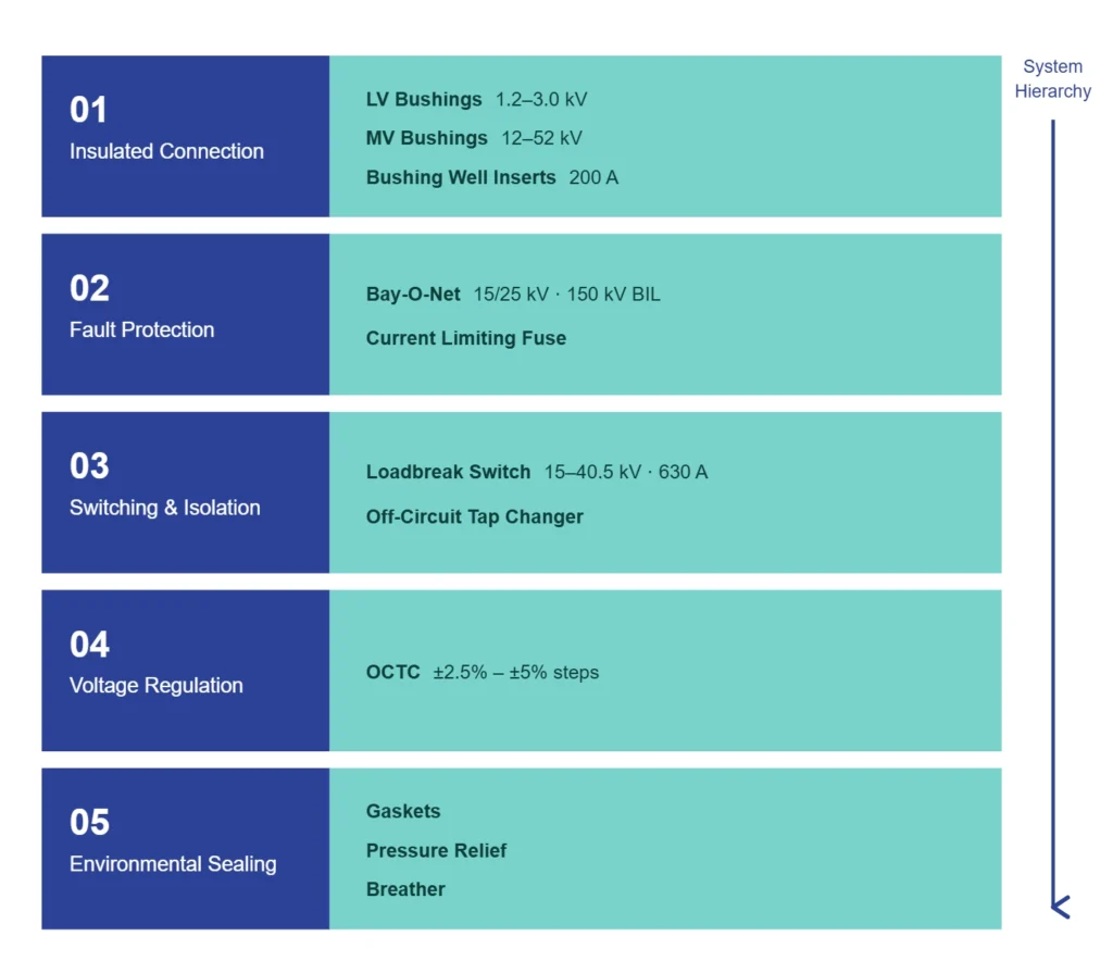
The Five Functional Layers of a Distribution Transformer Accessory System
A distribution transformer accessory system organizes into five functional layers. Each layer addresses a specific engineering requirement — insulation integrity, fault protection, switching capability, voltage regulation, or environmental sealing. Mapping accessories to layers before writing a bill of materials reduces compatibility errors and makes verification systematic.
Layer 1 — Insulated Connection (Bushings and Bushing Well Inserts)
The insulated connection layer carries current between internal windings and external conductors while maintaining dielectric isolation from the transformer tank. Low voltage bushings serve the secondary winding, rated from 1.2 kV to 3.0 kV with continuous current capacities from 600 A to 5,000 A or above. Material options — high-temperature nylon (HTN), porous resin, and porcelain — suit different thermal and environmental conditions. Medium voltage bushings serve the primary winding across 12 kV–52 kV at current ratings from 55 A to 3,150 A, with ANSI porcelain, DIN porcelain, and epoxy configurations depending on project geography. Bushing well inserts provide the separable connector interface on the MV side, rated at 200 A continuous in 15/25 kV and 15/25/35 kV voltage classes. The well insert and mating MV bushing must share the same voltage class — field commissioning records show that mismatches here are among the most common accessory interface errors on distribution projects.
Layer 2 — Fault Protection (Fuse Assemblies)
Bay-O-Net fuse assemblies, rated at 15/25 kV with a 150 kV BIL, clear low-to-moderate overcurrents up to approximately 3,500 A while allowing hot-stick field replacement without transformer shutdown. Current limiting fuses intercept high-magnitude faults above this threshold, interrupting fault current within a half-cycle before destructive peak levels are reached. Coordination between the two is mandatory — specifying either component without checking the handoff current boundary leaves part of the fault spectrum unprotected.
Layer 3 — Switching and Isolation
Loadbreak switches, rated at 15–40.5 kV and 630 A, perform make-and-break operations on energized pad-mounted transformers using stored-energy quick-action mechanisms operable by hook stick. Off-circuit tap changers, rated at 15/25/35 kV and 63–125 A, adjust transformer turns ratio only after the transformer is fully de-energized. Operating a tap changer under load risks contact arcing and internal insulation damage.
Layer 4 — Voltage Regulation
Distribution-class tap changers typically provide adjustment steps of ±2.5% or ±5% of rated voltage, with discrete positions selected to compensate for network voltage variation. Position selection is a de-energized, planned activity — not a real-time regulation function.
Layer 5 — Environmental and Sealing
Tank gaskets, pressure relief devices, oil-level indicators, and breather assemblies maintain internal dielectric fluid integrity under service conditions. These fall outside ZeeyiElec’s core accessory scope but are noted here because environmental failures in this layer directly affect the performance and service life of Layers 1 through 4.
Five-layer functional architecture of a distribution transformer accessory system, mapping each layer to its primary components, voltage class, and current rating range from insulated connection through environmental sealing (ZeeyiElec, 2026).
[Expert Insight] — Layer Specification Sequencing
Always confirm Layer 1 (bushing voltage class and BIL) before selecting Layer 2 (fuse assembly BIL rating) — they must align.
Layer 3 switch type (loadbreak vs. tap changer) is determined by whether energized switching or voltage adjustment is the operational requirement — not interchangeable.
Layer 5 is frequently omitted from accessory BOMs because it is assumed to be the transformer OEM’s responsibility; confirm scope allocation explicitly with the transformer supplier before purchase order release.
How the Layers Interact — System-Level Coordination Logic
Individual accessory layers do not operate in isolation. Each layer’s electrical parameters constrain the design space of adjacent layers, and a fault event or switching operation activates multiple layers in a defined sequence.
Insulation Coordination Across Layers
Every accessory mounted on a given transformer must share a consistent BIL. A 15 kV class distribution transformer typically carries a BIL of 95 kV across its bushing, bushing well insert, and fuse assembly interfaces. Mixing components with different BIL ratings — for example, a 95 kV BIL bushing well insert paired with a 150 kV BIL MV bushing — does not create a stronger system. It creates an insulation discontinuity at the interface that becomes the preferential breakdown path under impulse or switching transient conditions. [VERIFY STANDARD: IEC 60071-1 — BIL assignment methodology for distribution accessories]
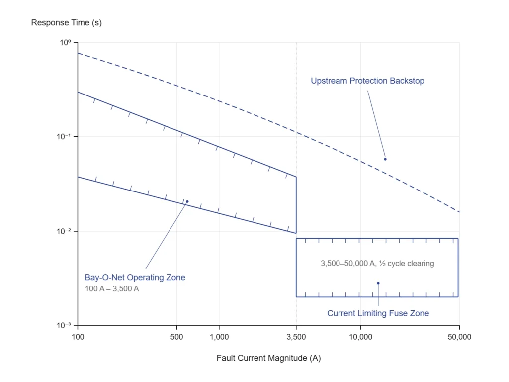
Fault Protection Sequence
When a fault develops on the transformer secondary or within the tank, the protection layer responds in a current-magnitude-dependent sequence. Bay-O-Net fuses clear overloads and moderate faults up to approximately 3,500 A. Above this threshold, the current limiting fuse operates within a half-cycle, limiting let-through energy to levels the transformer tank and connected cables can survive. Upstream protection — feeder breaker or recloser — acts as the final backstop.
This sequence only functions as designed when the two fuse types are selected as a coordinated pair. The handoff current boundary must be verified against the transformer’s available fault current at the installation point.
Switching and Tap Changer Interlock Logic
A loadbreak switch may interrupt rated load current at 630 A on an energized transformer. An off-circuit tap changer must never be moved while the transformer carries load. In correctly configured systems, a physical interlock prevents tap changer operation unless the transformer has been isolated. Field experience from distribution substation commissioning shows that absent or bypassed interlocks are a recurring root cause of tap changer contact damage — a failure mode that typically requires internal inspection and extended outage for repair.
The authority framework governing accessory interface requirements at the transformer system level is the IEC 60076 series on power transformers, which establishes the electrical parameter boundaries — rated voltage, insulation level, and tapping range — that accessory specifications must satisfy.
For engineers cross-referencing how these coordination principles apply to specific component selection, the complete selection map for transformer accessories provides parameter-level guidance across the bushing, fuse, and switching families.
Fault event response timeline for a coordinated Bay-O-Net and current limiting fuse protection scheme, delineating operating zones from 100 A overload to 50,000 A bolted fault with upstream protection backstop boundary (ZeeyiElec, 2026).
Matching Accessory Architecture to Distribution Project Voltage Class
Voltage class is the primary filter in transformer accessory selection. It determines bushing insulation grade, fuse assembly BIL rating, switch interrupting capability, and tap changer contact design — simultaneously, across all five functional layers. Applying voltage class systematically before evaluating any other parameter eliminates the largest category of accessory incompatibility errors before they reach procurement.
Voltage-Class Selection Matrix
Voltage Class
MV Bushing
LV Bushing
Fuse Configuration
Switch Rating
Tap Changer
10–15 kV
ANSI/epoxy, 95 kV BIL
HTN or resin, 1.2–2.0 kV
Bay-O-Net 15 kV + CLF
Loadbreak 15 kV, 630 A
OCTC 15 kV, 63–125 A
25 kV
ANSI/DIN, 125–150 kV BIL
Resin or porcelain, 2.0–3.0 kV
Bay-O-Net 25 kV + CLF
Loadbreak 25 kV, 630 A
OCTC 25 kV, 63–125 A
35 kV
DIN/epoxy, 150–170 kV BIL
Porcelain, 2.0–3.0 kV
CLF primary + Bay-O-Net backup
Loadbreak 38–40.5 kV, 630 A
OCTC 35 kV, 63–125 A
Transformer kVA Rating
Transformer kVA rating influences LV bushing current capacity. A 2,500 kVA unit at 15 kV may require LV bushings rated at 3,500 A or above — a parameter that HTN bushings handle reliably but that porcelain designs of equivalent voltage class may not accommodate in the same dimensional envelope.
Available Fault Current
Available fault current at the installation point determines whether the Bay-O-Net / current limiting fuse coordination boundary is correctly positioned. On feeders with available fault currents exceeding 10,000 A symmetrical, current limiting fuse selection must be verified against let-through energy limits, not simply matched by voltage class alone.
Mounting Configuration
Mounting configuration — pad-mounted versus pole-mounted — affects switch and fuse assembly type. Pad-mounted transformers in North American distribution practice predominantly use dead-front loadbreak switches and sidewall-mounted Bay-O-Net assemblies. Pole-mounted units in other geographies may use live-front bushing configurations with different fuse mounting geometry.
Field Compatibility Verification
Voltage class agreement across all accessories is a necessary condition, not a sufficient one. Dimensional interface compatibility — bushing flange diameter, well insert throat geometry, tap changer shaft coupling — must be confirmed against the transformer OEM’s drawings. Dimensional mismatches between voltage-class-correct but OEM-incompatible components represent a secondary tier of commissioning delays after voltage class errors are eliminated.
Engineers specifying accessories across these voltage classes can reference the loadbreak switch and off-circuit tap changer series pages for parameter-level compatibility data alongside the matrix above.
Field Realities — Common Architecture Gaps in Distribution Projects
Accessory system failures in distribution projects rarely trace back to component manufacturing defects. Field investigation data consistently points to specification gaps, procurement disconnects, and operational procedure errors as the dominant root causes.
Gap 1 — Bushing-to-Well Interface Mismatch
A 25 kV distribution project specified MV bushings correctly at 25 kV class but carried forward a 15 kV bushing well insert from a previous transformer batch in the project BOM. The two components were sourced on separate line items from different suppliers, and voltage class cross-referencing was not part of the project’s accessory acceptance checklist. The error surfaced during pre-energization insulation resistance testing, when the interface failed to meet dielectric withstand requirements. Replacement added approximately 3–4 weeks to the commissioning schedule. Prevention requires a column-by-column voltage class audit of the accessory BOM before purchase order release.
Gap 2 — Fuse Coordination Omitted at Design Stage
On a 15 kV rural feeder project, current limiting fuses were specified as the sole transformer protection device — Bay-O-Net assemblies were omitted on the basis that the current limiting fuse provided complete protection. During service, a moderate overload fault estimated at approximately 1,800 A caused the current limiting fuse to operate — well within Bay-O-Net clearing capability. The consequence was an unnecessary scheduled outage for full-fuse replacement, rather than a simple hot-stick Bay-O-Net element swap restoring service within minutes. Treating the two fuse technologies as a coordinated pair, with explicit documentation of the handoff current boundary, prevents both incorrect device operation and extended restoration time.
Gap 3 — Tap Changer Operated Under Load
Field personnel unfamiliar with the operational distinction between loadbreak switches and off-circuit tap changers have, in documented cases, adjusted tap changer position while the transformer remained energized. Immediate consequences include contact arcing within the tap changer mechanism. Depending on arc energy and contact condition, outcomes range from accelerated contact wear — reducing service life from a typical 10,000+ operation rating toward premature failure — to internal insulation damage requiring transformer withdrawal. Physical interlock labeling and a mandatory de-energization step in the commissioning procedure are the primary mitigations.
Failure patterns described reflect field observations across distribution transformer installations; occurrence rates vary with project execution quality, procurement rigor, and personnel training level.
[Expert Insight] — BOM Audit Before PO Release
Cross-reference voltage class on every accessory line item against the transformer nameplate — not just the project voltage level.
Flag any accessory sourced from a supplier not previously used on that transformer OEM’s units for dimensional compatibility review.
Confirm fuse pair coordination (Bay-O-Net + CLF handoff boundary) as a mandatory engineering sign-off step, not a supplier assumption.
A 30-minute BOM audit before purchase order release routinely prevents 3–4 week commissioning delays.
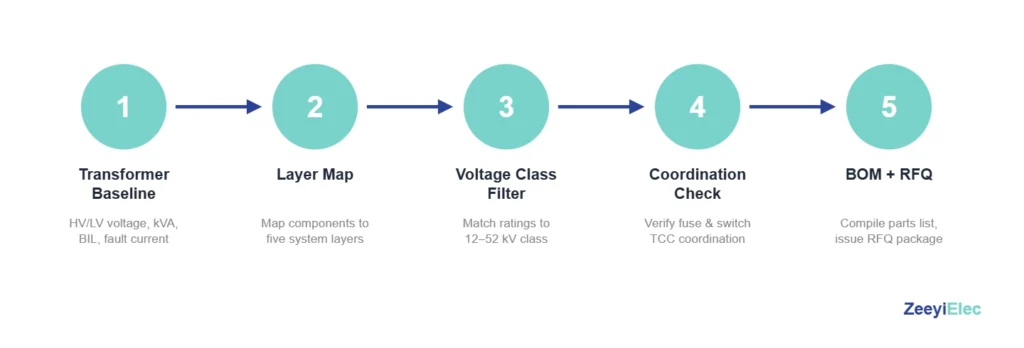
Specifying a Complete Transformer Accessory System — Engineer’s Framework
A complete accessory system specification requires five sequential steps. Skipping any step transfers the resulting ambiguity downstream — into supplier clarification cycles, procurement delays, or field incompatibilities that are significantly more costly to resolve than the specification time they appear to save.
Step 1 — Establish the Transformer Baseline
Collect the transformer’s rated HV and LV voltages, kVA rating, BIL designation, available fault current at the installation point, and mounting configuration. These are the fixed inputs that all accessory selections must satisfy.
Step 2 — Map Required Functional Layers
Confirm which of the five layers apply to the project scope. Not every installation requires all five — a straightforward pole-mounted unit may omit the loadbreak switch layer entirely. Documenting in-scope layers before selecting components prevents both over-specification and gaps.
Step 3 — Select by Voltage Class and Current Rating
Apply the voltage-class matrix as the primary filter. Confirm BIL alignment across all selected components before proceeding. Flag any component from a different voltage class bracket for mandatory engineering review.
Step 4 — Verify Coordination Parameters
Confirm the Bay-O-Net and current limiting fuse handoff boundary against available fault current. Confirm bushing-to-well insert voltage class match. Confirm tap changer current rating against transformer load profile.
Step 5 — Build the Accessory BOM and Submit RFQ
Structure the BOM by functional layer, with voltage class, current rating, BIL, and interface standard noted for each line item. Use ZeeyiElec’s transformer accessories RFQ checklist as a specification framework, and the full transformer accessories product range for series-level coverage across 10–35 kV distribution applications.
Five-step specification workflow for a complete distribution transformer accessory system, from transformer baseline collection through functional layer mapping, voltage class filtering, coordination verification, and BOM/RFQ submission (ZeeyiElec, 2026).
Standards and Authority References for Transformer Accessory Systems
Transformer accessory specifications reference multiple standards bodies — IEC for international and most export markets, ANSI/IEEE for North American projects, and CIGRE technical brochures for protection coordination and insulation design guidance.
Standards Map by Functional Layer
Functional Layer
Standard
Scope
Insulated Connection (Bushings)
IEC 60137
Bushings for AC voltages above 1 kV — dimensional, electrical, and test requirements
Insulated Connection (Bushings)
ANSI/IEEE C57.19.00
General requirements for power apparatus bushings — North American projects
Fault Protection (Fuses)
IEC 60282-1
Current limiting fuses for AC systems above 1 kV — ratings, test methods, marking
Fault Protection (Fuses)
IEC 60549
High-voltage fuses for transformer protection — expulsion and current limiting types
Switching and Isolation
IEC 60265-1
High-voltage switches 1 kV–52 kV — loadbreak switch performance and test requirements
Voltage Regulation (Tap Changers)
IEC 60214-1
Tap changers — performance requirements, test methods, application guide
Insulation Coordination
IEC 60071-1
BIL assignment, rated withstand voltages, standard voltage levels
Power Transformer Interface
IEC 60076-1
General requirements — rated quantities, tapping designations, accessory interface parameters
Applying Standards in Practice
Standards define minimum performance thresholds and test methodologies — they do not resolve every project-specific compatibility question. IEC 60137 governs bushing electrical and dimensional requirements but does not mandate dimensional compatibility with a specific transformer OEM’s tank flange. That compatibility layer requires cross-referencing the transformer manufacturer’s interface drawings against the accessory supplier’s dimensional datasheet. IEC 60282-1 establishes current limiting fuse rating requirements but does not prescribe the coordination boundary with Bay-O-Net assemblies — that calculation remains the specifying engineer’s responsibility.
North American and Export Market Divergence
Projects destined for North American utility networks typically require ANSI/IEEE compliance for bushings (C57.19 series) and may reference IEEE C37 series guidance for switching device coordination. Export projects to IEC-governed markets reference the IEC series above. When a project specification references both systems, the more stringent test requirement governs unless the project specification states otherwise.
For engineers navigating IEC parameter requirements during procurement, the IEC specification cheat sheet for accessory procurement consolidates critical parameters and testing requirements into a single procurement reference.
Frequently Asked Questions
What is a transformer accessory system in distribution power?
A transformer accessory system is the integrated set of components — bushings, fuses, switches, and tap changers — that connect a distribution transformer’s internal windings to the external network while managing insulation integrity, fault protection, and voltage adjustment as an interdependent system rather than isolated parts.
How many functional layers does a typical distribution transformer accessory system include?
Most distribution transformers operating at 10–35 kV require five functional layers: insulated connection, fault protection, switching and isolation, voltage regulation, and environmental sealing — though not every project activates all five, depending on transformer type and mounting configuration.
What is the correct way to coordinate Bay-O-Net fuses and current limiting fuses?
Bay-O-Net fuses clear low-to-moderate fault currents up to approximately 3,500 A, while current limiting fuses handle higher fault magnitudes above that threshold within a half-cycle — the handoff boundary must be verified against available fault current at the installation point, not assumed from voltage class alone.
Why must bushing well inserts and MV bushings share the same voltage class?
A voltage class mismatch between a bushing well insert and its mating MV bushing creates a dielectric discontinuity at the interface, producing a preferential breakdown path under impulse or switching transient conditions — even if both components individually meet their own rated specifications.
When should a loadbreak switch be specified instead of an off-circuit tap changer?
A loadbreak switch is required when the application demands switching on an energized transformer — making or breaking rated load current up to 630 A — while an off-circuit tap changer is specified when voltage ratio adjustment is needed and the transformer can be de-energized for that operation.
What secondary variables refine accessory selection beyond voltage class?
Transformer kVA rating (which drives LV bushing current capacity), available fault current at the installation point (which governs fuse coordination boundary positioning), and mounting configuration (pad-mounted versus pole-mounted) are the three variables that refine accessory selection within a confirmed voltage class.
How does IEC 60076 relate to transformer accessory specification?
IEC 60076-1 establishes the transformer-level parameters — rated voltage, insulation level, and tapping range — that accessory specifications must satisfy at each interface point; individual accessory performance requirements are governed by component-specific standards such as IEC 60137 for bushings and IEC 60282-1 for current limiting fuses.
yoyo shi
Yoyo Shi writes for ZeeyiElec, focusing on medium-voltage accessories, transformer components, and cable accessory solutions. Her articles cover product applications, technical basics, and sourcing insights for global electrical industry buyers.