Transformer Accessories Series

200A Bushing Well & Inserts for Distribution Transformers

Available in 15/25kV and 15/25/35kV classes, engineered for reliable insulation and stable interface performance.

OEM/ODM Support Fast Technical Response Export Documentation
Voltage Class 15/25kV & 15/25/35kV
Current Rating 200A Continuous
Application Distribution Transformers
Product Definition

What Is a Bushing Well in a Transformer System?

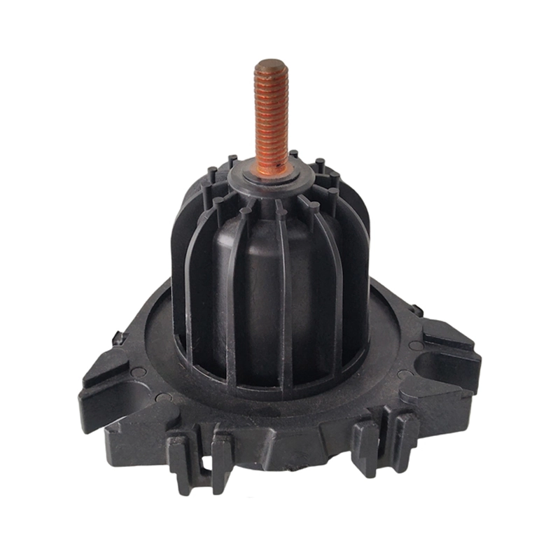
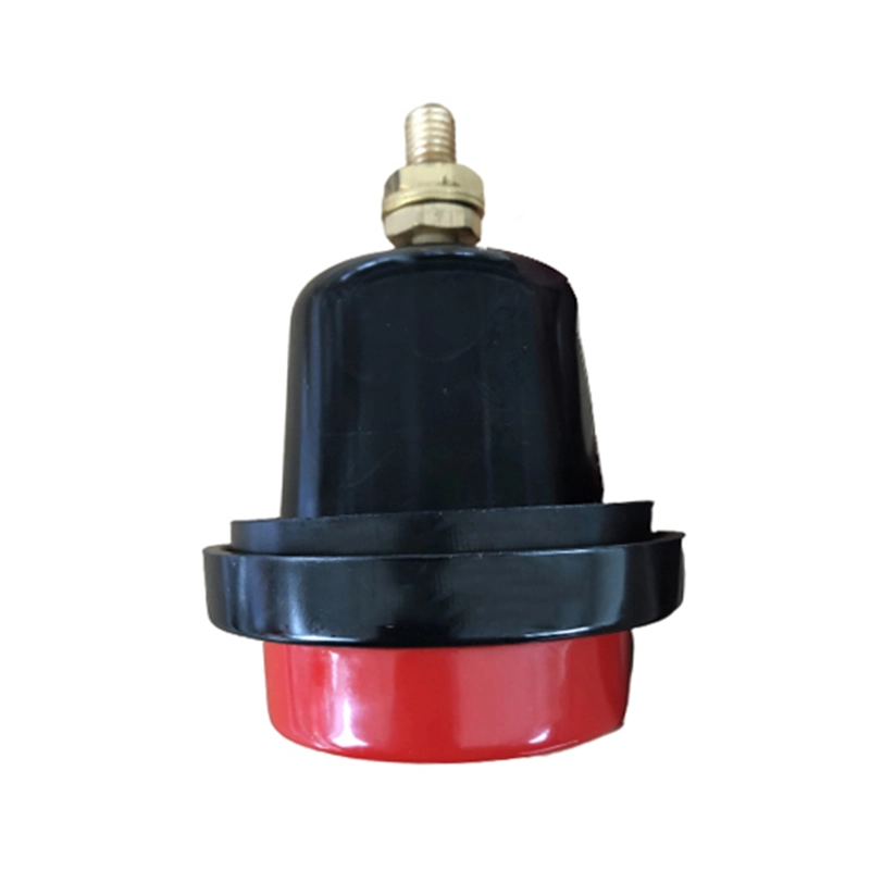
A bushing well is an insulated interface component mounted on the transformer tank, functioning as the primary transformer bushing well interface. As a critical insulated well component for distribution transformer applications, it provides a secure foundation for the bushing well insert system, ensuring reliable transition between internal winding leads and external connections.

  • 1
    Electrical Insulation — supports dielectric isolation under operating voltage.
  • 2
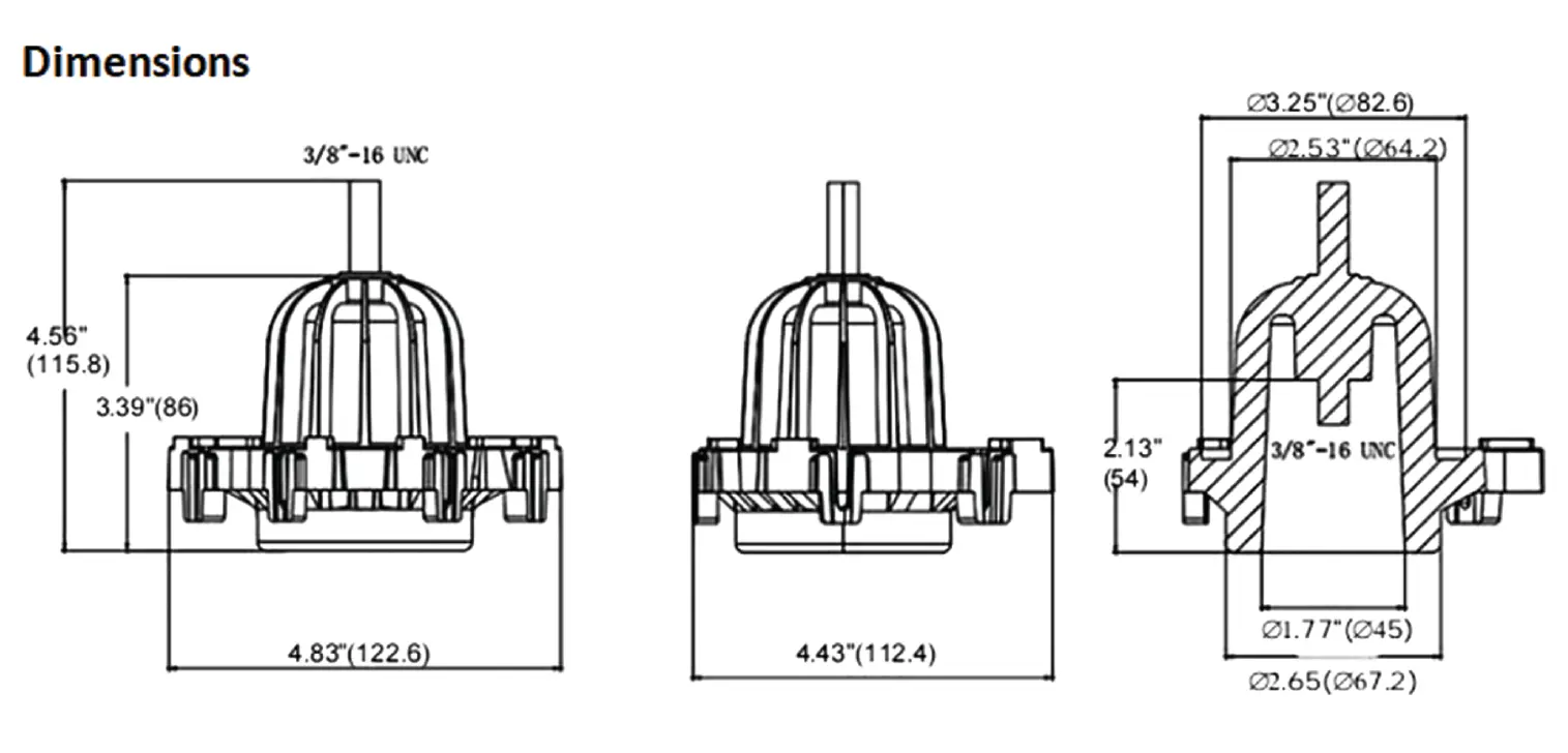
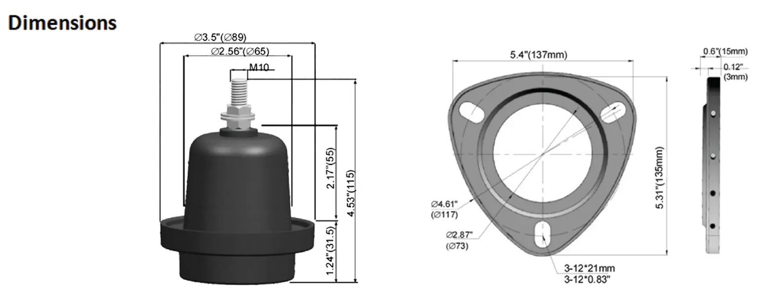
    Mechanical Interface — provides stable mounting and connection geometry.
  • 3
    System Compatibility — works with matched insert and connector configurations.
ZeeyiElec offers 200A bushing well configurations for 15/25kV and 15/25/35kV distribution transformer applications.
External Connection Cable / Elbow Connector
Interface Accessory Bushing Insert
This Product Bushing Well
Mounting Base Transformer Tank Wall
Series Configurations

Choose the Right 200A Bushing Well Configuration

ZeeyiElec provides two 200A bushing well configurations for distribution transformers: HTN 15/25/35kV class and epoxy resin 15/25kV class. Select based on voltage class, insulation target, interface preference, and project compatibility.

Zeeyi Electric 200A 15/25/35kV class HTN bushing well with tri-clamp mounting for distribution transformer

200A HTN Bushing Well (15/25/35kV Class)

  • Rated Voltage 15 / 25 / 35 kV
  • Material HTN (High Temp Nylon)
  • BIL Rating 150 kV
  • Mounting Style Tri-clamp
Ordering Ref SJTGZ-35-200 / -R
Request Quote
Zeeyi Electric 200A 15/25kV class epoxy resin bushing well with stud clamp mounting for oil-immersed transformer

200A Epoxy Bushing Well (15/25kV Class)

  • Rated Voltage 15 / 25 kV
  • Material Epoxy Resin
  • BIL Rating 95 kV
  • Mounting Style Stud Clamp
Ordering Ref TGZ-(15)25-200
Request Quote

Technical Comparison (200A Class)

ItemHTN 15/25/35kVEpoxy Resin 15/25kV
Rated Voltage15 / 25 / 35 kV15 / 25 kV
Continuous Current200 A200 A
BIL / Full Wave Crest150 kV95 kV
Mounting StyleTri-clampStud Clamp
Power Freq Withstand (1 min)50 kV45 kV
DC Withstand (15 min)53 kV
Switching Current10kA rms (0.17s)
Thread / Stud3/8″-16 UNCM10
Ordering CodeSJTGZ-35-200 / -RTGZ-(15)25-200
GasketIncludedIncluded
Dimension drawing of Zeeyi Electric 200A 35kV HTN bushing well showing tri-clamp mounting and 3/8-16 UNC stud
HTN Tri-clamp Mounting: Requires 3-stud clamp configuration. Standard 3/8″-16 UNC interface. Refer to local standards for cutout dimensions.
Dimension drawing of Zeeyi Electric 200A 15/25kV epoxy bushing well with stud clamp mounting and M10 interface
Epoxy Stud Clamp Mounting: Uses standard stud clamps (Figure 1 in datasheet). M10 Thread interface. Ensure gasket is properly seated during installation.
Technical Data

Engineering Specifications

Comprehensive comparison of electrical ratings, insulation withstand levels, and mechanical interfaces.

A. Electrical Ratings

ParameterHTN 15/25/35kVEpoxy 15/25kV
Rated Voltage15/25/35 kV15/25 kV
Continuous Current200 A200 A
Switching Current10kA rms (0.17s)

B. Insulation & Withstand

ParameterHTN 15/25/35kVEpoxy 15/25kV
BIL / Full Wave150 kV95 kV
AC Withstand (1 min)50 kV45 kV
DC Withstand (15 min)53 kV

C. Interface & Mechanical

ParameterHTN 15/25/35kVEpoxy 15/25kV
Thread / Stud3/8″-16 UNC (Fixed/Removable)M10 Thread
Installation FormExternal clamp side-wallExternal clamp side-wall
ApplicationSingle-/Three-phase TransformerSingle-/Three-phase Transformer
GasketIncludedIncluded

D. Ordering Information

ConfigurationOrdering Code
HTN, fixed studSJTGZ-35-200
HTN, removable studSJTGZ-35-200-R
Epoxy resinTGZ-(15)25-200

Dimensions & Interface Notes

  • Detailed dimensions should be verified against final drawings.
  • HTN supports 3/8″-16 UNC stud options (fixed or removable).
  • Epoxy resin uses M10 thread interface.
  • For retrofit projects, please confirm mounting geometry and sealing boundary.
Why ZeeyiElec

Built for Reliable Supply, Technical Clarity, and Project Execution

Beyond product ratings, successful transformer accessory sourcing depends on stable quality, clear specifications, and responsive coordination. ZeeyiElec supports OEM and replacement programs with engineering-oriented execution.

Stable Material & Process Control

Consistent manufacturing workflow for repeatable insulation and interface performance.

Specification-Driven Communication

Technical parameters, interface details, and ordering logic are aligned before quotation.

Batch Consistency for Projects

Controlled dimensional and assembly consistency for multi-unit project delivery.

Routine Verification Before Shipment

Core checks are completed before release to reduce field-side uncertainty.

Export-Ready Documentation Support

Supports commercial and technical document coordination for international orders.

Responsive Engineering Follow-Up

Fast communication on model matching, compatibility questions, and project changes.

Engineering Selection

How to Select the Right 200A Bushing Well (15/25kV & 15/25/35kV)

Use this step-by-step guide to match voltage class, insulation requirement, interface type, and ordering configuration before submitting your RFQ.

01

Confirm Voltage Class

Identify whether your project requires 15/25kV or 15/25/35kV insulation class based on grid requirements.

02

Confirm Electrical Duty

Verify continuous current requirement (200A) and relevant impulse withstand (BIL) expectations.

03

Check Interface

Confirm thread type:
HTN: 3/8″-16 UNC
Epoxy: M10

04

Verify Installation

Check tank-side mounting geometry, sealing area, and retrofit constraints against drawings.

05

Finalize Code

Match final selection:
SJTGZ-35-200
TGZ-(15)25-200

Common Mistakes

  • Selecting by voltage only, without checking interface/thread compatibility.
  • Ignoring retrofit geometry and sealing boundary conditions.
  • Sending RFQ without required technical inputs, causing repeated revisions.

📝 Information to Prepare Before RFQ

  • Required voltage class (15/25kV or 15/25/35kV)
  • Quantity and project type (OEM / replacement)
  • Interface requirement (3/8″-16 UNC or M10)
  • Installation boundary or drawing reference
  • Target delivery timeline and destination market
Execution Assurance

Quality Control & Documentation Support

ZeeyiElec simplifies the supply chain with a standardized verification protocol and complete export documentation, ensuring your bushing well project is delivered accurately and on time.

🛡️ Standardized Quality Protocol

  • Requirement Alignment Double-check voltage class (15/25/35kV), interface thread, and ordering code before production release.
  • Dimensional Verification Go/No-Go gauge testing for 3/8″-16 UNC or M10 threads to ensure connector compatibility.
  • Insulation Integrity Routine withstand voltage and visual inspection for surface imperfections or sealing area defects.
  • Pre-Shipment Audit Final quantity count, model consistency check, and packing condition review before release.

📄 Handover Documentation & Support

Standard Export Docs

  • Commercial Invoice & Packing List
  • Bushing well model confirmation sheet
  • Bill of Lading / Airway Bill
  • Product Specification Sheet

Technical Support

  • Transformer bushing well interface checklist
  • Installation Interface Drawing
  • Batch Traceability Reference
  • Post-Delivery Technical Q&A
FAQ & Resources

Common Questions & Technical References

Clear answers on interface definition, selection boundaries, and compatibility, plus quick access to official standards.

Related Resources

A bushing well insert provides the conductive and interface function inside the insulated well structure, enabling a stable connection between internal transformer conductors and external separable components.
A bushing well is typically the insulated interface body mounted at the tank boundary, while a transformer bushing is a broader category. In pad-mounted interfaces, well + insert configurations are commonly used together.
Selection should follow project insulation class, system design margin, and specification requirements. If higher insulation class coverage is required, 15/25/35kV configurations are generally preferred.
This series includes configurations using 3/8″-16 UNC (fixed/removable stud options) and M10 thread interfaces. Final matching should be confirmed against project drawings.
No. They are different interface/application categories and should not be mixed without compatibility confirmation. Always verify mating standard and connector type before ordering.
Yes, but retrofit suitability depends on tank-side geometry, sealing boundary, thread match, and insulation class. Pre-confirmation is recommended before PO release.
Voltage-only selection can cause interface mismatch (thread, stud form, mating boundary), leading to assembly or sealing issues even when voltage class is correct.
Recommended inputs include voltage class, required quantity, interface/thread requirement, drawing reference (if available), and destination/project type.
Yes. Gasket inclusion and ordering codes are provided in the specifications section. Confirm final code/version during quotation review.
For electrical installation framework and safety context, refer to recognized standards resources such as NEC/NFPA references, and combine them with project-specific engineering requirements.