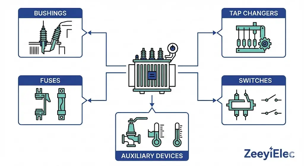
A transformer’s core and windings receive most engineering attention during specification. Yet accessories—bushings, tap changers, fuses, switches, and auxiliary devices—account for a disproportionate share of field failures. Industry data indicates that 15–25% of transformer outages trace back to accessory malfunction rather than core or winding defects
This pattern exists because accessories serve as interface points. Bushings bridge internal insulation with external connections. Tap changers introduce moving contacts into sealed, oil-filled environments. Fuses must coordinate with upstream protection while withstanding transient inrush currents. Each accessory introduces potential failure modes that proper selection can minimize.
Mechanical compatibility: Mounting dimensions, thread patterns, and gasket interfaces must align with transformer tank design
The sections that follow map each accessory category to its selection criteria—positioning accessories as integral to transformer reliability rather than procurement afterthoughts.
Bushing Selection Criteria — Voltage Class, BIL, and Creepage Requirements
Bushings represent the most failure-prone transformer accessories when improperly specified. These components enable high-voltage conductors to pass through grounded transformer tanks while maintaining dielectric integrity across air, oil, and solid interfaces.
Low-Voltage Bushings (≤1 kV)
Secondary-side bushings handle high currents at relatively low voltages. Selection focuses on:
Current rating: Match transformer secondary full-load current with 20% margin (typical range: 200–3000 A)
Thread configuration: Verify compatibility with existing cable lugs and bus connections
Mounting style: Flange-mounted or threaded stud configurations based on tank design
Material: Porcelain offers superior weathering resistance; polymer reduces weight and fracture risk
Medium-Voltage Bushings (1–36 kV)
Primary-side bushings require careful attention to insulation coordination. The selection sequence follows a defined hierarchy:
Step 1 — Voltage Class: Match or exceed system nominal voltage Step 2 — BIL Rating: Ensure impulse withstand meets or exceeds transformer nameplate BIL Step 3 — Creepage Distance: Calculate based on pollution severity at installation site Step 4 — Current Rating: Size for transformer primary full-load current plus margin
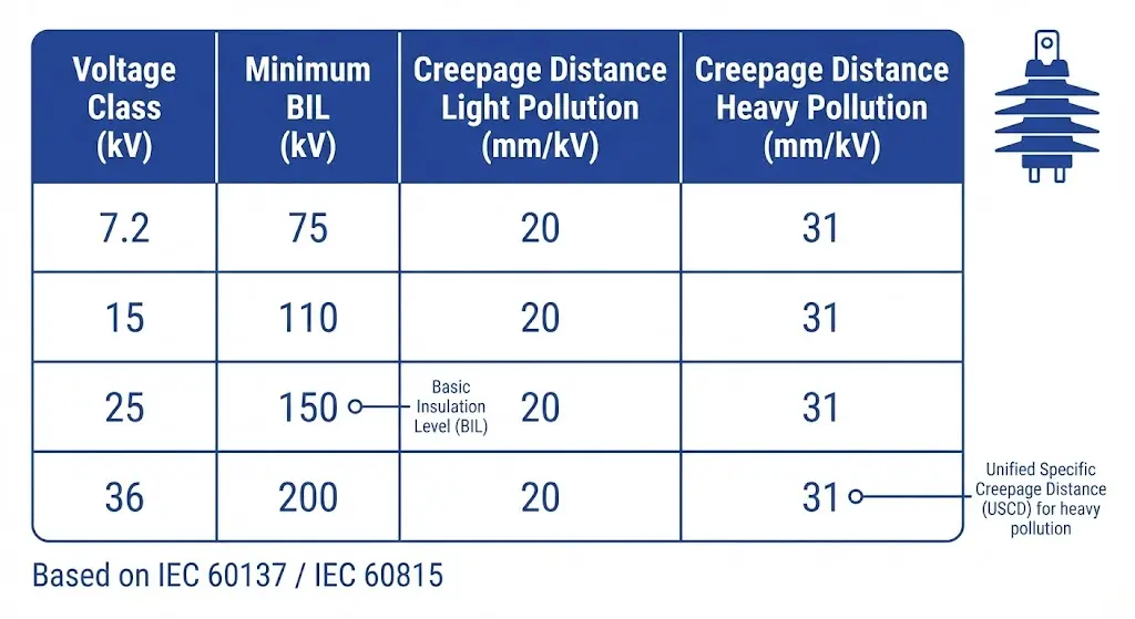
According to IEC 60137, bushings must demonstrate partial discharge levels below 10 pC at 1.1 × Um and thermal stability under rated current. Creepage distance requirements per IEC 60815 range from 16 mm/kV (light pollution) to 31 mm/kV (very heavy pollution).
Modern medium-voltage bushings utilize capacitive grading to distribute electric field stress uniformly. The innermost layer typically experiences 3–5 kV/mm while outer layers see only 0.8–1.2 kV/mm—preventing localized breakdown.
Figure 1. Bushing selection parameters by voltage class showing minimum BIL ratings and creepage distance requirements for IEC pollution severity levels.
Voltage Class (kV)
Minimum BIL (kV)
Creepage — Light (mm/kV)
Creepage — Heavy (mm/kV)
7.2
60
16
25
15
95–110
16
25
25
125–150
20
31
36
170–200
25
31
[Expert Insight: Bushing Selection Field Observations]
Coastal installations require minimum 25 mm/kV creepage regardless of voltage class—salt fog contamination accelerates tracking failures
Polymer bushings outperform porcelain in seismic zones due to superior fracture resistance
Oil-side creepage is often overlooked; ensure internal creepage matches external requirements for contaminated oil conditions
Always verify mounting hole patterns before procurement—dimensional mismatches cause costly project delays
Tap Changer Selection — Off-Circuit vs. On-Load Decision Framework
Tap changers provide voltage regulation by adjusting the transformer turns ratio. The selection decision branches into two fundamentally different technologies with distinct cost, maintenance, and operational implications.
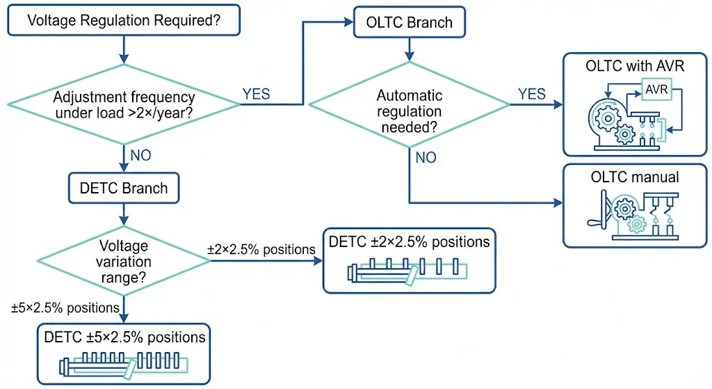
De-Energized Tap Changer (DETC): Manual operation requiring transformer de-energization. Typical position range: ±2 to ±5 positions at 2.5% per step. Cost-effective for applications requiring infrequent seasonal adjustments.
On-Load Tap Changer (OLTC): Automatic operation under full load. Typical position range: ±8 to ±16 positions. Essential for applications requiring continuous voltage regulation or automatic power factor correction.
The decision threshold centers on adjustment frequency. If voltage changes are needed more than twice yearly under load conditions, OLTC justifies its 5–10× cost premium. Industrial facilities with variable loads and utility substations serving voltage-sensitive customers typically require OLTC capability.
For distribution transformers with stable loading patterns, off-circuit tap changers provide reliable voltage adjustment at substantially lower cost and maintenance burden.
Figure 2. Tap changer type selection flowchart: DETC suits infrequent adjustments while OLTC enables continuous under-load voltage regulation.
Selection Factor
DETC (Off-Circuit)
OLTC (On-Load)
Operation mode
De-energized only
Under load
Typical positions
±2 to ±5
±8 to ±16
Regulation type
Manual/seasonal
Automatic/continuous
Relative cost
Baseline
5–10× higher
Maintenance
Minimal inspection
Regular contact/oil service
Best application
Distribution transformers
Substation, industrial feeders
Position count selection depends on expected voltage variation. A ±5×2.5% range accommodates ±12.5% total regulation—sufficient for most distribution applications. Transmission substations with wider voltage swings may require ±10×1.25% or similar extended ranges.
Fuse Selection for Transformer Protection — Ratings and Coordination
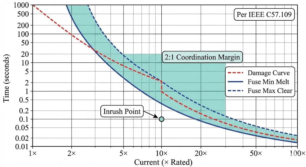
Transformer fuses must accomplish two competing objectives: interrupt fault currents rapidly while withstanding magnetizing inrush currents that reach 8–12 times rated current for 100–200 milliseconds. Improper sizing causes either nuisance operations during energization or inadequate protection during internal faults.
Current-Limiting Fuses
These devices use silver-sand construction to create high-resistance fulgurite within 4–8 milliseconds, limiting peak let-through current substantially below prospective fault levels. Selection parameters include:
Voltage rating: Must equal or exceed maximum system voltage
Continuous current: Size at ≥1.25× transformer full-load amperes
Interrupting capacity: Must exceed available fault current at installation point (typically 10–25 kA for distribution)
Current-limiting fuses excel at protecting against high-magnitude internal faults where rapid current limitation prevents catastrophic tank rupture.
Bay-O-Net Fuse Assemblies
Pad-mounted and submersible transformers require bay-o-net fuse assemblies with dual-element design:
Weak link element: Responds to external faults and overloads; replaceable without tank entry
Backup current-limiting element: Protects against internal faults; requires tank access for replacement
This configuration enables field maintenance of the most frequently operated element while maintaining internal fault protection.
Figure 3. Time-current coordination between transformer damage curve and fuse characteristics, showing required 2:1 margin per IEEE C57.109.
Per IEEE C57.109 (transformer through-fault current duration guide), the fuse maximum clearing time must maintain a 2:1 minimum margin below the transformer through-fault damage curve at all current levels. For a typical 500 kVA distribution transformer with 5.75% impedance, maximum fault current reaches approximately 17× rated current—requiring careful fuse-transformer coordination analysis.
Transformer kVA
Primary Voltage (kV)
Recommended Fuse Rating (A)
Minimum Interrupting (kA)
25–75
15
3–8
10
100–167
15
10–15
10
250–500
15
20–40
10
500–1000
25
25–50
12
Temperature derating applies to all fuse installations. Continuous current capability decreases approximately 0.4% per degree Celsius above 25°C reference—a 40°C ambient reduces effective rating by 6%.
[Expert Insight: Fuse Coordination Field Lessons]
Always request manufacturer coordination curves—catalog ratings alone are insufficient for proper time-current analysis
Cold-load pickup following extended outages can trip undersized fuses; size for 150% of calculated inrush in areas with high air conditioning load
Bay-o-net weak links should be stocked as maintenance spares; lead times during storm restoration can exceed acceptable outage durations
Auxiliary Accessories — Switches, Breathers, Gaskets, and Indicators
Beyond primary electrical accessories, transformer reliability depends on properly selected auxiliary components that manage oil quality, pressure, and operational switching.
Loadbreak Switches: Required for pad-mounted transformers to enable under-load disconnection. Selection criteria include:
Load-break current rating (typically 200–600 A)
Voltage class matching primary bushings
Mounting configuration (deadfront vs. live-front)
Breathers and Desiccants: Silica gel breathers prevent moisture ingress during thermal breathing cycles. Size capacity relative to transformer oil volume—typically 1–2 kg silica gel per 1000 liters of oil. Self-regenerating breathers reduce maintenance burden for remote installations.
Gaskets: Material selection depends on oil compatibility and temperature range:
Nitrile rubber (NBR): Standard mineral oil applications to 100°C
Silicone: Extended temperature range to 150°C
Viton (FKM): Synthetic fluids and aggressive chemical environments
Oil Level Indicators: Magnetic-type indicators suit hermetically sealed units; direct-reading gauges work for conservator-type designs. Ensure indicator range matches expected oil expansion from minimum to maximum operating temperature.
Pressure Relief Devices: Set pressure must match transformer design—typically 10–15 psi (69–103 kPa) for distribution class. Verify compatibility with existing tank pressure ratings before replacement.
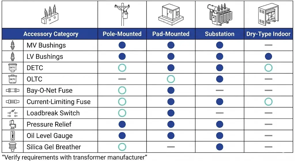
Transformer Type vs. Accessory Selection Matrix
Different transformer configurations demand different accessory complements. The matrix below consolidates selection requirements by transformer category—serving as a quick-reference for procurement specifications.
Figure 4. Transformer type vs. accessory selection matrix indicating required (●), optional (○), and not applicable (—) accessories by transformer category.
Accessory Category
Pole-Mounted
Pad-Mounted
Substation
Dry-Type Indoor
MV Bushings
Required
Required
Required
Typically integral
LV Bushings
Required
Required
Required
Terminal blocks
DETC
Common
Common
Optional
Optional
OLTC
Rare
Optional
Common
Rare
Bay-O-Net Fuse
N/A
Required
N/A
N/A
Current-Limiting Fuse
External (cutout)
Internal/External
External
External
Loadbreak Switch
N/A
Required
Optional
N/A
Pressure Relief
Required
Required
Required
N/A
Oil Level Gauge
Required
Required
Required
N/A
Silica Gel Breather
Required
Optional
Required
N/A
Buchholz Relay
N/A
N/A
Required (>5 MVA)
N/A
Common specification errors observed in field procurement reviews:
Underspecifying bushing creepage for coastal or industrial pollution environments
Omitting altitude derating for installations above 1000 m elevation
Selecting DETC when load patterns actually require OLTC capability
Mismatching fuse interrupting ratings to available fault current
Field Verification Checklist Before Procurement
Before finalizing any transformer accessory purchase order, verify these critical parameters against actual field conditions:
Confirm transformer nameplate data: Record kVA rating, voltage ratio, BIL, impedance percentage, and cooling class
Measure mounting dimensions: Bushing hole spacing, tap changer pocket diameter, and gasket surface flatness
Document environmental conditions: Altitude above sea level, ambient temperature range (min/max), pollution severity level per IEC 60815
Verify available fault current: Obtain utility fault current data or calculate from system impedance
Confirm applicable standards: IEC vs. IEEE/ANSI—mixing standards creates interoperability problems
Check spare stock compatibility: Standardize accessories across fleet where possible to reduce inventory burden
Review utility specifications: Some utilities mandate specific manufacturers or testing certifications
Assess logistics constraints: Lead times, shipping dimensions, and import/customs requirements for international procurement
Evaluate lifecycle cost: Initial price plus expected maintenance, spare parts, and eventual replacement
Request test certificates: Factory test reports, type test certificates, and material certifications as applicable
This checklist prevents the most common procurement errors—dimension mismatches, environmental misrating, and standards conflicts that delay projects and compromise reliability.
Source Transformer Accessories Built for Long-Term Reliability
Proper accessory selection extends transformer service life while reducing unplanned maintenance interventions. The frameworks presented here—bushing voltage class tables, tap changer decision trees, fuse coordination principles, and type-specific matrices—provide systematic guidance for specification development.
ZeeyiElec manufactures the complete range of transformer accessories covered in this guide: medium-voltage and low-voltage bushings, off-circuit tap changers, current-limiting fuses, bay-o-net assemblies, loadbreak switches, and auxiliary devices. Our engineering team provides specification assistance for non-standard configurations, altitude derating calculations, and coordination studies.
Request a technical consultation or quotation for your transformer accessory requirements. Include transformer nameplate data and installation environment details for accurate recommendations.
Frequently Asked Questions
Q: What transformer accessories fail most frequently in service? A: Bushings and tap changer contacts account for the majority of accessory-related failures, typically due to moisture ingress, contamination buildup, or inadequate creepage distance for the installation environment.
Q: How do I determine the correct bushing BIL rating for my transformer? A: Start with the transformer nameplate BIL value as the minimum requirement, then verify that creepage distance meets pollution severity levels at your specific installation site—coastal and industrial locations often require higher creepage than inland installations.
Q: When does an on-load tap changer justify its cost premium over off-circuit types? A: OLTC becomes cost-effective when voltage adjustments are needed more than twice yearly under load conditions, or when automatic voltage regulation is required for variable industrial loads or voltage-sensitive utility customers.
Q: What fuse sizing margin should I use for transformer protection? A: Size continuous current rating at minimum 1.25 times transformer full-load amperes, with interrupting capacity exceeding available fault current by at least 20% to account for system growth.
Q: Can transformer accessories from different manufacturers be interchanged? A: Physical interchangeability depends on adherence to dimensional standards (IEC or ANSI), but electrical coordination requires case-by-case verification—fuse characteristics and tap changer step voltages vary between manufacturers even at identical ratings.
Q: How does altitude affect transformer accessory selection? A: Above 1000 m elevation, reduced air density decreases both dielectric strength and cooling efficiency—specify accessories with higher BIL ratings (typically 1% increase per 100 m above 1000 m) and derate continuous current capacity accordingly.
Q: What documentation should I request when purchasing transformer accessories? A: Request factory routine test reports, type test certificates for design verification, material certifications for critical components (bushing insulators, fuse elements), and manufacturer coordination curves for protective devices.
yoyo shi
Yoyo Shi writes for ZeeyiElec, focusing on medium-voltage accessories, transformer components, and cable accessory solutions. Her articles cover product applications, technical basics, and sourcing insights for global electrical industry buyers.