Блок предохранителей Bay-O-Net - это маслопогруженное защитное устройство вытеснительного типа, устанавливаемое через боковую стенку распределительного трансформатора, смонтированного на площадке. Его функция специфична: прерывать низкие и умеренные токи повреждения до примерно 3 500 А симметрично до того, как устойчивая энергия повреждения повредит первичную обмотку или разгерметизирует бак. В отличие от предохранителей общего назначения, он предназначен для замены в полевых условиях под напряжением с помощью инструментов с горячими палочками, без снятия бака или слива изоляционного масла.
Основные элементы конструкции
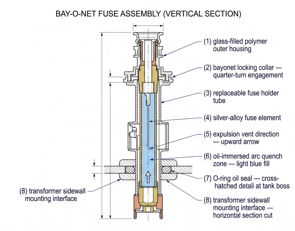
Внешний корпус из стеклонаполненного термопластичного полимера или глазурованного фарфора обеспечивает первичный изоляционный барьер между держателем предохранителя под напряжением и заземленным резервуаром. Внутри сменная трубка держателя предохранителя содержит плавкий элемент из серебра или оловянного сплава, откалиброванный под определенную характеристику тока времени. При замыкании элемент плавится; окружающее трансформаторное масло гасит дугу. Отводная трубка направляет ионизированный газ в сторону от активной зоны изоляции. Байонетная запорная муфта фиксирует держатель на четверть оборота и обеспечивает точку зацепления горячей палочкой для вставки и извлечения.
Интерфейс с боковой стенкой трансформатора, установленной на панели
Узел продевается через обработанную бобышку на боковой стенке резервуара. Диаметр отверстия бобышки и геометрия резьбы должны соответствовать корпусу предохранителя с точностью ±0,5 мм на посадочной поверхности уплотнительного кольца; отклонения сверх этого приводят к неравномерному сжатию уплотнения и протеканию масла при термоциклировании в диапазоне от -40 °C до +105 °C. Класс напряжения сборки 15 кВ или 25 кВ должен соответствовать номинальному напряжению первичной обмотки трансформатора, а ее базовый уровень импульсной изоляции (BIL), обычно 95-150 кВ, должен быть согласован с BIL системы. По опыту ввода в эксплуатацию, несоответствие BIL между корпусом предохранителя и первичной обмоткой трансформатора является одной из наиболее часто встречающихся ошибок в спецификации в проектах модернизации, в которых заменяющие узлы поставляются не оригинальным производителем, а другим поставщиком.
Для более широкого представления о том, как сборки Bay-O-Net вписываются в архитектуру защиты и коммутации трансформаторов, см. обзор продукции аксессуары для трансформаторов охватывает все семейство аксессуаров.
Поперечное сечение сборки предохранителя Bay-O-Net: внешний полимерный корпус, байонетная запорная муфта, сменная трубка держателя предохранителя, элемент предохранителя из серебряного сплава, направление выхлопа, зона дуги, погруженная в масло, кольцевое уплотнение и интерфейс крепления к боковой стенке трансформатора.
Основные технические критерии для оценки поставщиков блоков предохранителей Bay-O-Net
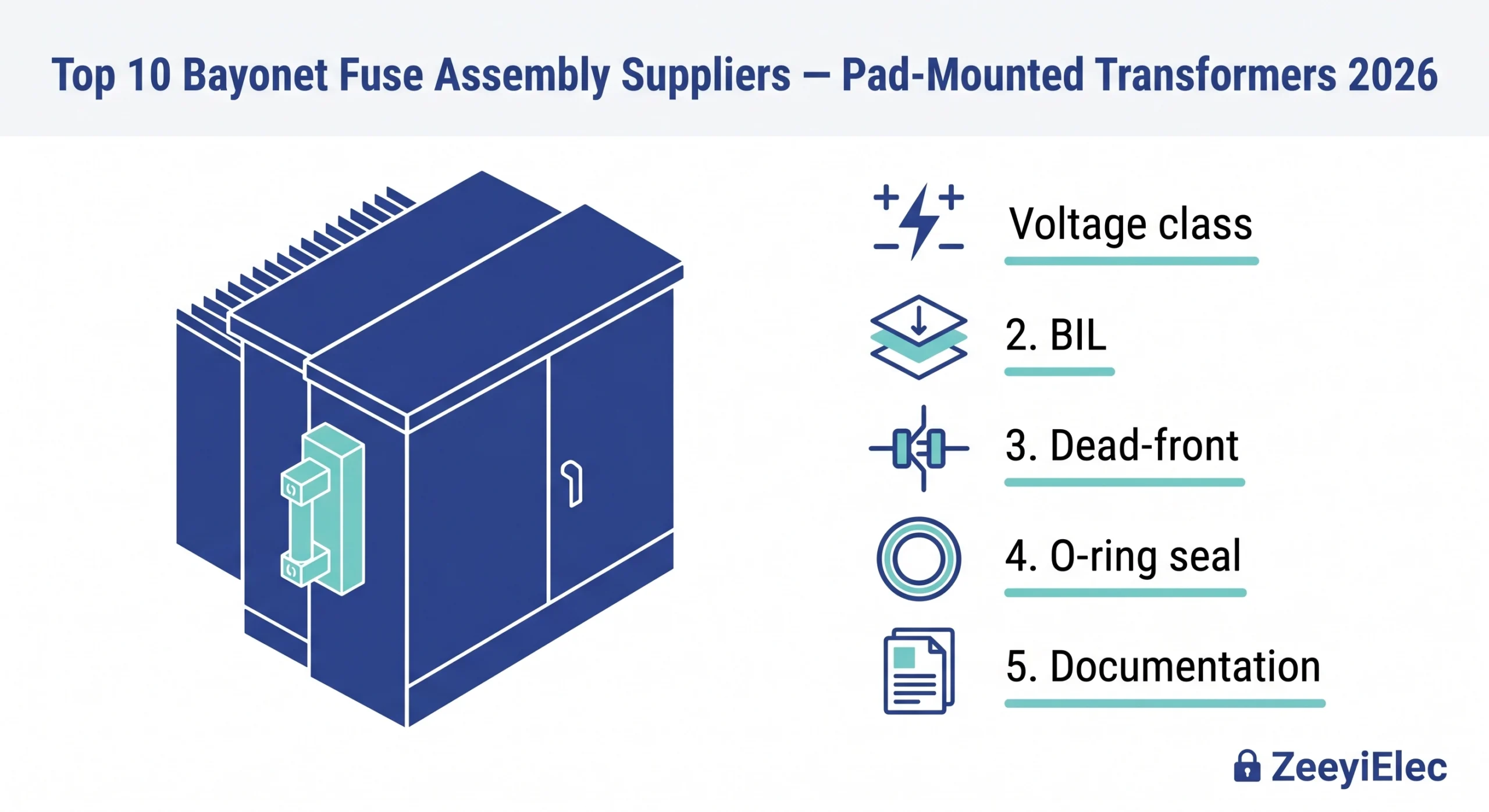
Выбор поставщика чаще всего проваливается не при составлении короткого списка, а при определении спецификации. Каталог, в котором указано “покрытие 15 кВ / 25 кВ”, почти ничего не говорит о том, согласуется ли сборка с вашим предохранителем, ограничивающим ток, или выдержит ли она двадцатилетнее термоциклирование в прибрежной установке. Эти пять критериев представляют собой технически обоснованную систему оценки, применимую к любому поставщику на рынке.
Покрытие класса напряжения и рейтинга BIL
Для трансформаторов, устанавливаемых на площадках в Северной Америке, два преобладающих класса напряжения - 15 кВ и 25 кВ, с номинальными значениями BIL 95 кВ и 125-150 кВ соответственно. Заявленный поставщиком BIL должен быть подтвержден протоколом импульсных испытаний, а не только каталожной декларацией. Несоответствие BIL между корпусом блока предохранителей и первичной втулкой трансформатора является постоянным источником диэлектрических отказов в проектах модернизации.
Номинальный непрерывный ток и прерывистость при замыкании
Номиналы непрерывного тока обычно варьируются от 100 до 200 А, охватывая распределительные трансформаторы мощностью от 167 кВА до 2 500 кВА при напряжении 15 кВ. Потолок симметричного прерывания 3 500 А определяет границу координации, при превышении которой последовательный токоограничивающий предохранитель должен справляться с устранением повреждения. Поставщики, которые не могут предоставить кривые время-токовых характеристик (ВТХ), делают невозможным анализ координации на этапе предшествования, что само по себе является дисквалифицирующим фактором при закупках для коммунальных служб.
Безопасная конструкция Dead-Front и возможность работы с горячим прилипанием
Конструкция с тупым фронтом, исключающая воздействие на металлическую поверхность под напряжением во время извлечения предохранителя, является обязательным условием при монтаже на панель. По опыту эксплуатации, сборки с неадекватными функциями защиты от проворачивания на держателе предохранителя после 5-8 лет погружения в масло часто требуют извлечения двумя людьми, что создает незапланированную угрозу безопасности во время планового технического обслуживания.
Материал корпуса и герметичность
Корпуса из стеклонаполненных термопластичных полимеров обладают ударопрочностью и устойчивостью к УФ-излучению, достаточной для большинства климатических условий умеренного климата, в то время как фарфор остается предпочтительным в условиях сильного загрязнения или в тропической среде, где устойчивость к слеживанию поверхности имеет решающее значение. Рабочие характеристики кольцевых уплотнений во всем диапазоне температур от -40 °C до +105 °C должны быть проверены в сравнении с изоляционным маслом трансформатора типа минерального масла, FR3 или силиконовой жидкости, поскольку несовместимые эластомерные соединения вызывают набухание уплотнений и утечку масла в течение 2-3 термических циклов.
Гибкость конфигурации OEM и готовность к экспорту документации
Возможность настройки номинального тока, спецификации резьбы и геометрии корпуса в соответствии с существующей крышкой резервуара зачастую более ценна, чем любой стандартный продукт. Не менее важен полный пакет документации, готовой к экспорту, - протоколы испытаний, сертификаты стандартных испытаний, сертификат происхождения и письмо о соответствии. На сайте Аксессуары для трансформаторов Контрольный список RFQ переводит эти критерии непосредственно в структурированный запрос поставщику.
[Экспертный взгляд] - Инжиниринг закупок
Поставщик, предлагающий только отчеты о стандартных испытаниях, не продемонстрировал характеристики прерывания короткого замыкания на симметричной границе 3 500 А, запросив специальные отчеты об испытаниях.
Кривые TCC являются обязательными: без них невозможно аналитически проверить координацию предохранителя с предохранителями, расположенными выше по току.
Указания резьбы (UNC/UNF против метрической) на габаритных чертежах предотвращают наиболее распространенные случаи несовместимости при модернизации.
Топ 10 поставщиков байонетных плавких вставок для трансформаторов с накладным монтажом
Представленные ниже поставщики охватывают североамериканские, европейские и азиатско-тихоокеанские каналы закупок. Ни один поставщик не является оптимальным по всем параметрам проекта, поэтому перед составлением короткого списка проведите перекрестную проверку каждой заявки по пяти критериям оценки.
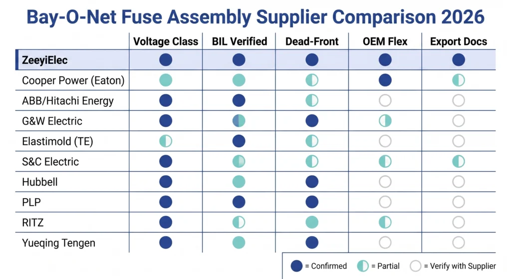
Матрица сравнения поставщиков
Поставщик
Регион
Класс напряжения
Диапазон BIL
Текущий диапазон
OEM/экспорт
Ключевой дифференцирующий фактор
ZeeyiElec
CN
15 / 25 кВ
95-150 кВ
100-200 A
✅ Полный
Гибкость OEM/ODM; полная экспортная документация
Cooper Power Systems (Eaton)
США
15 / 25 / 35 кВ
95-200 кВ
100-200 A
Частичный
Глубокое наследие ANSI; обширная библиотека TCC
ABB / Hitachi Energy
CH/JP
15-36 кВ
95-200 кВ
100-200 A
Частичный
Покрытие двойным стандартом IEC + ANSI
G&W Electric
США
15 / 25 кВ
95-150 кВ
100-200 A
Частичный
Интеграция экосистемы коммутационного оборудования на панели
Elastimold (TE Connectivity)
США
15 / 25 кВ
95-150 кВ
100-200 A
Частичный
Совместимость с разъемами с мертвой стороны
S&C Electric
США
15 / 25 / 35 кВ
95-200 кВ
100-200 A
Частичный
Координация защиты Инженерная поддержка
Hubbell Power Systems
США
15 / 25 кВ
95-150 кВ
100-200 A
Частичный
Корпус с мертвой передней стенкой из коммунальных материалов; экосистема с горячим прилипанием
Изделия из предварительно сформированных линий (PLP)
США
15 / 25 кВ
95-150 кВ
100-200 A
Ограниченный
Уточняйте полный объем Bay-O-Net непосредственно у поставщика
Приборные трансформаторы RITZ
DE
12-36 кВ
95-170 кВ
55-200 A
Ограниченный
IEC-первичный; согласование европейской проектной документации
Yueqing Tengen Electric
CN
15 / 25 кВ
95-150 кВ
100-200 A
✅ Полный
Конкурентоспособный по цене экспортный уровень OEM; высокая производительность
S-01 - ZeeyiElec (Wenzhou Zeeyi Electric Co., Ltd.)
Предохранительные сборки Bay-O-Net серии PRNT классов 15 кВ и 25 кВ, BIL до 150 кВ, с резьбой OEM и конфигурацией номинального тока. Полный пакет экспортной документации: протоколы испытаний, сертификаты, сертификат происхождения - является стандартным для каждого заказа. Полные размерные данные доступны на сайте Серия предохранителей Bay-O-Net стр..
S-02 - Cooper Power Systems (Eaton)
Один из самых давних североамериканских источников предохранителей для трансформаторов вытеснительного типа, с обширной опубликованной библиотекой TCC, позволяющей легко координировать предохранители без проведения индивидуальных испытаний. Сильное наследие ANSI в области коммунального хозяйства и широкий охват классов напряжения до 35 кВ.
S-03 - ABB / Hitachi Energy
Двойная документация по стандартам ANSI/IEC и глобальная сервисная сеть снижают риск цепочки поставок в многонациональных проектах EPC. Охват классов напряжения от 15 кВ до 36 кВ с отчетами о типовых испытаниях, заверенными свидетелями, доступен для обеих схем.
S-04 - G&W Electric
Сборки разработаны для прямого сопряжения с системами распределительных устройств G&W, устанавливаемых на площадках, что снижает риск совместимости размеров, когда весь корпус трансформатора поставляется от одного поставщика.
S-05 - Elastimold (TE Connectivity)
Логичный выбор в тех случаях, когда в качестве основного кабельного интерфейса используются разъемные соединители 200 или 600 А с мертвым фронтом из одного семейства продуктов, что упрощает инвентаризацию в полевых условиях и совместимость с инструментами для горячего монтажа.
S-06 - S&C Electric Company
Обеспечивает анализ тока повреждения и исследования координации между предохранителями наряду с поставкой оборудования, что особенно ценно в проектах, где сборки Bay-O-Net должны быть скоординированы в нескольких трансформаторных отсеках. Сайт Руководство по согласованию Bay-O-Net и токоограничивающих предохранителей подробно описывает эту логику координации.
S-07 - Hubbell Power Systems
Наследие в области распределительного оборудования для коммунальных служб распространяется на блоки предохранителей с мертвым фронтом, разработанные для надежной работы в горячем режиме в ограниченных корпусах, устанавливаемых на площадках, в соответствии со стандартами закупок североамериканских кооперативных и инвесторских коммунальных служб.
S-08 - Линейные изделия с предварительной формовкой (PLP)
В первую очередь они используются для подвесного распределительного оборудования; прежде чем включать их в конкурентный запрос предложений, убедитесь непосредственно в компании PLP, что их предложение Bay-O-Net полностью соответствует требованиям монтажа на боковую стенку и погружения в масло для трансформаторов, устанавливаемых на площадках.
S-09 - Приборные трансформаторы RITZ
Документация серии IEC 60282 ориентирована на напряжение от 12 кВ до 36 кВ; хорошо подходит для экспортных проектов, в которых указаны критерии эффективности предохранителей IEC, а не ANSI, особенно на европейских и ближневосточных рынках коммунальных услуг.
S-10 - Yueqing Tengen Electric
Конкурентоспособные цены на объемные экспортные заказы от производителя OEM-уровня, расположенного в Вэньчжоу. Запросите протоколы типовых испытаний и проверьте прослеживаемость испытательной лаборатории BIL, прежде чем брать на себя обязательства по закупкам.
Оценочная таблица поставщиков для сборок предохранителей Bay-O-Net: десять поставщиков оценивались по пяти критериям закупок - охват класса напряжения, проверка номинала BIL, конструкция с мертвым фронтом, гибкость конфигурации OEM и готовность экспортной документации.
Стандарты и сертификация, которые должны проверять покупатели ландшафта
Номинальные значения напряжения по каталогу ничего не значат без прослеживаемых доказательств испытаний. Сертификационный ландшафт охватывает две параллельные системы ANSI/IEEE для североамериканских коммунальных служб и IEC для большинства экспортных рынков, и покупатели, работающие в обоих регионах, должны понимать, что требует каждая система, прежде чем принимать документацию поставщика.
Система стандартов ANSI/IEEE
Стандарт ANSI/IEEE C37.41 устанавливает требования к проектированию и производственным испытаниям высоковольтных предохранителей экспульсионного типа: номинальное максимальное напряжение, номинальный непрерывный ток, номинальный прерывающий ток и методы испытаний TCC. Протокол типовых испытаний должен содержать прямую ссылку на C37.41 и указывать аккредитованную лабораторию, которая проводила испытания на прерывание короткого замыкания. Согласование аксессуаров на уровне трансформатора подпадает под ANSI/IEEE C57.12.00, регулирующий распределительные трансформаторы с жидкостным погружением и их интерфейсные компоненты. Отчеты о типовых испытаниях подтверждают согласованность производства, но не заменяют отчеты о типовых испытаниях. Поставщики, предлагающие только обычную документацию, не продемонстрировали соответствие полному пределу характеристик прерывания на симметричной границе 3 500 А.
Составление карт стандартов МЭК для экспортных рынков
В многонациональных или высокоспециализированных электротехнических проектах очень важно ориентироваться в стандартах высоковольтных предохранителей. IEC 60282-2 В нем четко рассматриваются плавкие вставки вытеснительного типа на напряжение выше 1 кВ, строго определены номинальное напряжение, номинальный ток, категории отключающей способности, а также последовательность испытаний, необходимых для установления классификации характеристик.
В процессе закупок и проектирования систем инженеры и покупатели часто сталкиваются со следующими проблемами, связанными с пересечением стандартов:
Несовместимость при тестировании: Сборка, прошедшая только испытания ANSI, не является автоматически совместимой с IEC. Поскольку базовые методики испытаний отличаются, для достижения соответствия IEC требуется дополнительное тестирование при определенных конфигурациях цепей IEC.
Расхождение региональных табличек (распространенная ошибка при закупках): Расхождения в региональных номиналах часто приводят к несоответствию оборудования. Например, сборка с рейтингом IEC на 17,5 кВ (Um) не подходит непосредственно к системе класса ANSI на 15 кВ. Такая замена никогда не должна производиться без предварительной проверки согласования изоляции с конкретным базовым уровнем изоляции (BIL) системы.
Лучшие практики для соблюдения двух стандартов: Для проектов, требующих строгого соблюдения обоих стандартов, наиболее сильной позицией при закупках является консолидированная документация. Вам следует потребовать протоколы типовых испытаний, выданные одной аккредитованной лабораторией, которые подтверждают соответствие оборудования требованиям как IEC, так и ANSI.
Совместимость в полевых условиях: Подборка блоков предохранителей к реальным конфигурациям трансформаторов с монтажной панелью
Сертификация по стандартам устанавливает минимальные эксплуатационные характеристики. Совместимость в полевых условиях определяет, правильно ли установлен узел, надежно ли он герметичен и сохраняет ли он работоспособность в течение двадцатилетнего срока эксплуатации. Большинство отказов в полевых условиях, связанных с аксессуарами, происходит не из-за отказа плавкого элемента при неисправности, а из-за несоответствия размеров, ухудшения герметичности и ограничений по зазору в корпусе, которые не учитываются ни в одном техническом описании.
Монтажные размеры боковых стенок и геометрия сопряжения с резервуаром
Несоответствие спецификаций резьбы между поставщиками стандартов ANSI (дюймовая резьба UNC/UNF) и OEM-комплектами с метрической конфигурацией - постоянная проблема совместимости в проектах модернизации. Всегда запрашивайте габаритный чертеж с явными обозначениями резьбы перед оформлением заказа на поставку Одного обозначения номинального класса напряжения недостаточно для подтверждения совместимости монтажа.
Герметизация в масляной среде и поведение при термоциклировании
Уплотнительные кольца из буны-N (нитрила) адекватно работают в минеральном масле, но демонстрируют ускоренное сжатие в среде натурального эфира FR3, снижая силу уплотнения после 3-5 термических циклов. При полевых испытаниях трансформаторов, установленных на площадках, в условиях пустыни с высокой суточной температурой, превышающей 40 °C, в течение 4-7 лет наблюдалось просачивание масла на бобышке плавкой вставки, в которой использовались неспецифицированные кольцевые уплотнения, даже если плавкий элемент оставался полностью работоспособным.
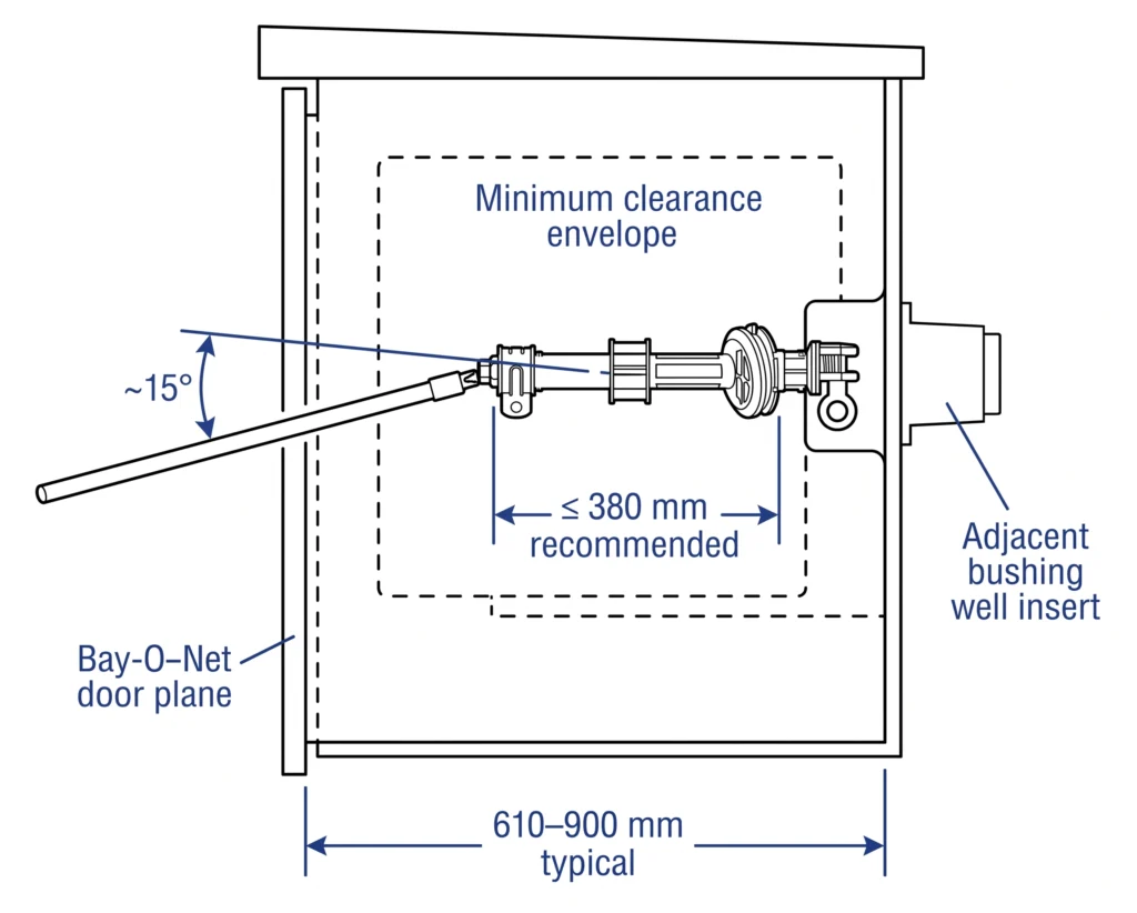
Зазоры при работе с горячими клеями внутри корпусов с накладным монтажом
Корпуса, устанавливаемые на площадку, ограничивают доступную рабочую глубину, которая обычно составляет от 610 мм до 900 мм между плоскостью передней двери и задней стенкой резервуара. Сборки предохранителей с трубками-держателями общей длиной более 380 мм могут мешать соседним кабельным вводам или втулочным колодцам при извлечении, что приводит к нарушению зазора, не определяемому только по чертежам каталога. Дуга отсоединения байонета на четверть оборота (90°) также должна быть подтверждена в пределах имеющегося бокового зазора перед закупкой.
Запросите у производителя трансформатора чертеж внутреннего зазора, а также данные о размерах бобышек бака в качестве стандартной части любого запроса предложений Bay-O-Net. Сайт обзор продукции кабельных аксессуаров содержит параллельное руководство по проверке зазоров для оконечных компонентов, находящихся в одном корпусе.
Схема боковых зазоров при установке блока предохранителей Bay-O-Net в корпус трансформатора с площадкой: предельная длина трубки держателя предохранителя (рекомендуется ≤ 380 мм), угол вставки горячего ключа (~15° от горизонтали), граница минимального зазора и пространственная привязка соседних втулочных отверстий.
[Экспертный взгляд] - Полевая установка
Материал уплотнительных колец должен быть указан в соответствии с фактическим типом изоляционной жидкости трансформатора - минеральное масло, FR3 или силикон, не зависящий от класса напряжения или страны происхождения.
Тип резьбы босса (ANSI дюймовая или метрическая) должен быть подтвержден габаритным чертежом OEM-производителя трансформатора перед закупкой.
Первые установки с новым поставщиком требуют проверки физического макета перед принятием массового заказа.
Красные флажки закупок и этапы проверки качества
Поставщик, выглядящий надежным при составлении короткого списка, все равно может поставить несоответствующие узлы, если проверка документации прекращается на этапе изучения каталога. Следующие шесть показателей взяты из опыта закупок по проектам комплектующих для трансформаторов среднего напряжения.
Красный флаг 1 - отчеты о рутинных испытаниях представлены вместо отчетов о типовых испытаниях
Обычные испытания подтверждают габаритные размеры и основные электрические характеристики, но не демонстрируют полное прерывание на симметричной границе 3 500 А. Запросите отчет о типовых испытаниях, уточните название лаборатории и убедитесь, что дата отчета соответствует текущему производственному проекту, а не устаревшему поколению продукции.
Красный флаг 2 - Значения BIL указаны без лабораторной прослеживаемости
Указание в техническом паспорте “BIL: 150 кВ” без соответствующего протокола импульсных испытаний, прослеживаемого аккредитованной лабораторией, является непроверенным заявлением. Рассматривайте сборки от таких поставщиков как не прошедшие испытания на BIL до тех пор, пока не будут предоставлены достоверные доказательства испытаний третьей стороной.
Красный флаг 3 - Несоответствие класса напряжения между расстоянием изоляции корпуса и номиналом заводской таблички
Для сборки класса 15 кВ минимальное внешнее расстояние ползучести в условиях категории II по степени загрязнения IEC обычно составляет ≥ 25 мм на кВ номинального напряжения, что дает примерно 375 мм общего расстояния ползучести. Сборки с размерами корпуса, не соответствующими этому диапазону для заявленного класса напряжения, указывают либо на неправильно классифицированный продукт, либо на корпус, разработанный для более низкого класса напряжения и перемаркированный.
Красный флаг 4 - аномальные сроки выполнения заказа, предполагающие замену запасов
Поставщик, предлагающий сборку менее чем за 5 рабочих дней при количестве более 50 единиц, в то время как производство с конфигурацией обычно занимает 3-6 недель, требует прямого запроса. Быстрая доступность может указывать на замену неспецифических запасов, полученных от вторичного поставщика без раскрытия информации.
Красный флаг 5 - Отсутствие сертификации материалов на совместимость с маслом
Поставщики, которые не могут предоставить заявление о совместимости материалов, охватывающее минеральное масло, FR3 и силиконовую жидкость, не проводили соответствующих испытаний на совместимость. Деградация уплотнительных колец Buna-N в среде FR3 в течение 3-5 лет - это задокументированный способ отказа при отсутствии подтвержденных данных о совместимости.
Красный флаг 6 - Фотографирование одного образца без отслеживания партии
Каталоги с одной фотографией полированного изделия без маркировки партии или описания системы отслеживания производства должны стать поводом для запроса аудита фабрики до начала закупок. Прослеживаемость партии, привязывающая каждую единицу продукции к производственному циклу, партии сырья и протоколу стандартных испытаний, является основным требованием системы качества для аксессуаров хозяйственного назначения.
Источник блоков предохранителей Bay-O-Net для вашего проекта по установке трансформатора на площадку
Выбор правильного блока предохранителей Bay-O-Net требует большего, чем соответствие класса напряжения позиции в каталоге. Спецификация резьбы, согласование BIL, совместимость материалов уплотнительных колец и готовность экспортной документации - все это определяет, будет ли сборка работать правильно в течение всего срока службы и пройдет ли ваш груз таможенную очистку и заводские приемочные испытания без задержек.
Компания ZeeyiElec поставляет предохранители Bay-O-Net серии PRNT классов 15 кВ и 25 кВ, BIL до 150 кВ и номинальным током от 100 А до 200 А. Возможна OEM-конфигурация по спецификации резьбы, номинальному току и геометрии корпуса для прямого соответствия боссу бака вашего трансформатора. Протоколы типовых испытаний, сертификаты стандартных испытаний, сертификаты происхождения и письма о соответствии готовятся в стандартной комплектации для каждого заказа.
Чтобы получить точный технический ответ и коммерческое предложение, укажите в запросе три параметра: класс первичного напряжения и требования к BIL, спецификацию резьбы бобышки бака или ссылку на чертеж OEM, а также стандарт целевого рынка (ANSI или IEC).
Ознакомьтесь с полным ассортиментом аксессуаров для защиты и коммутации трансформаторов:
Свяжитесь с ZeeyiElec, предоставив спецификацию вашего проекта, для получения технической информации и предложения в течение одного рабочего дня.
Часто задаваемые вопросы
Что такое блок предохранителей Bay-O-Net и какой диапазон неисправностей он охватывает?
Блок предохранителей Bay-O-Net - это маслопогруженное защитное устройство вытеснительного типа, устанавливаемое на боковой стенке распределительного трансформатора, смонтированного на площадке, предназначенное для прерывания токов повреждения до примерно 3500 А симметричного тока до повреждения обмотки или разгерметизации бака. Оно является первой ступенью схемы защиты с двумя предохранителями, при этом последовательный токоограничивающий предохранитель может отключать более высокие токи повреждения, превышающие этот порог.
Какие классы напряжения существуют и как подобрать BIL к моему трансформатору?
Сборки Bay-O-Net для трансформаторов, устанавливаемых на площадках, чаще всего выпускаются в классах 15 кВ и 25 кВ, с номиналами BIL от 95 кВ до 150 кВ в зависимости от требований к координации изоляции системы. Выбранный BIL сборки должен соответствовать BIL первичной обмотки трансформатора, указанному на заводской табличке трансформатора, а не только номинальному классу напряжения системы.
Как выбрать правильный номинал непрерывного тока?
Номинальный ток основан на первичном токе полной нагрузки трансформатора, при этом предохранитель должен непрерывно выдерживать ток 100-200 А в зависимости от номинальной кВА трансформатора и первичного напряжения. Номинал также должен учитывать пусковые токи при включении, обычно в 8-12 раз превышающие номинальный ток в течение примерно 0,1 секунды, чтобы избежать неприятного срабатывания во время переключений.
Можно ли напрямую взаимозаменять сборки Bay-O-Net от разных поставщиков?
Взаимозаменяемость зависит от совместимости размеров: диаметр отверстия бобышки, спецификация резьбы и геометрия канавки уплотнительного кольца должны соответствовать оригинальному отверстию бака, а материал эластомера должен быть совместим с конкретной изоляционной жидкостью трансформатора. Даже если класс напряжения идентичен, различия в размерах или материалах у разных поставщиков могут нарушить целостность масляного уплотнения, поэтому перед заменой следует сверить их со спецификацией на монтаж, предоставленной производителем трансформатора.
Какие документы я должен потребовать от поставщика перед размещением заказа на поставку?
Минимальный пакет документации, соответствующий требованиям, включает в себя протокол типовых испытаний со ссылкой на применимый стандарт предохранителей ANSI или IEC, сертификат стандартных испытаний для производственной партии, габаритный чертеж с явными обозначениями резьбы, заявление о совместимости материалов уплотнительных колец и сертификат происхождения для получения разрешения на экспорт. Поставщики, не способные предоставить свидетельства о типовых испытаниях, прослеживаемые аккредитованной лабораторией, не должны приниматься для закупок коммунального класса независимо от цены.
В чем разница между предохранителем Bay-O-Net и токоограничивающим предохранителем на одном и том же трансформаторе?
Предохранитель Bay-O-Net использует механизм вытеснения, подходящий для устранения слабых и умеренных повреждений, и заменяется в полевых условиях с помощью инструментов с горячими палочками, в то время как токоограничивающий предохранитель прерывает высокомагнитные повреждения свыше 3500 А в течение полуцикла для предотвращения разрыва резервуара, но не подлежит замене в тех же рабочих условиях. Оба устройства устанавливаются последовательно, при этом каждое из них охватывает определенную часть спектра тока повреждения.
Как условия монтажа влияют на выбор плавкой вставки Bay-O-Net?
Окружающая среда с высокой дневной температурой ускоряет сжатие уплотнительных колец и разрушение масляных уплотнений, особенно в системах с жидкостями на основе натуральных эфиров FR3, где эластомеры Buna-N химически несовместимы. Прибрежные или сильно загрязненные места дополнительно требуют проверки расстояния между корпусами и могут предпочесть фарфор стеклонаполненному полимеру за более высокую стойкость к слеживанию поверхностей в течение всего номинального срока службы узла.
йойо ши
Йойо Ши пишет для ZeeyiElec, специализируясь на аксессуарах для среднего напряжения, компонентах трансформаторов и кабельных аксессуарах. В ее статьях рассказывается о применении продукции, технических основах, а также об особенностях поиска поставщиков для глобальных покупателей электротехнической промышленности.