Medium voltage cable accessories—terminations and joints spanning 6.6kV to 33kV—represent critical junction points where installation quality directly determines system reliability. Field data consistently shows that proper accessory selection accounts for only part of the reliability equation. Execution during installation carries equal or greater weight.
This quality control checklist covers pre-installation verification, cable preparation, technology-specific inspection protocols for both cold shrink terminations and heat shrink joints, and post-installation electrical testing. Whether commissioning a 15kV termination in a substation switchgear or inspecting an underground splice in a duct bank, these checkpoints help identify defects before energization—when correction remains practical and economical.
Why Installation Quality Control Prevents Most MV Accessory Failures
The uncomfortable truth from utility maintenance records: approximately 70–80% of MV cable accessory failures originate from installation defects, not manufacturing issues. A premium termination installed improperly will fail sooner than a standard product installed with meticulous attention.
The failure mechanism follows a predictable chain. Contamination introduced during cable preparation—dust particles, moisture films, skin oils, or semiconductor residue—creates localized stress concentrations at the insulation interface. These contamination sites become partial discharge inception points once the accessory is energized. Initial PD activity may measure below detection thresholds, but progressive erosion continues over months or years until catastrophic breakdown occurs.
Three critical installation parameters drive most failures:
Interface Preparation Quality — Surface contamination exceeding 10 μg/cm² of ionic residue creates conductive paths along stress control interfaces. Even microscopic particles invisible during visual inspection generate sufficient field distortion to initiate PD at operating voltage.
Dimensional Accuracy — Semiconductor screen removal lengths must match manufacturer specifications within ±2 mm. Excessive cutback creates unshielded insulation zones where tangential electrical stress causes surface tracking. Insufficient cutback prevents proper stress cone positioning.
Compression Integrity — Cold shrink and heat shrink accessories depend on continuous radial pressure (typically 0.2–0.6 MPa) against cable components. This pressure eliminates interfacial air gaps and ensures moisture sealing to IP68 ratings.
The economic case for rigorous QC is stark. A contamination-related termination failure on a 22kV distribution feeder generates emergency response costs, replacement materials at 3–5× original installation cost, customer outage penalties, and collateral damage assessment. Against this, proper QC execution adds perhaps 20–30 minutes per accessory—an extraordinary return on investment.
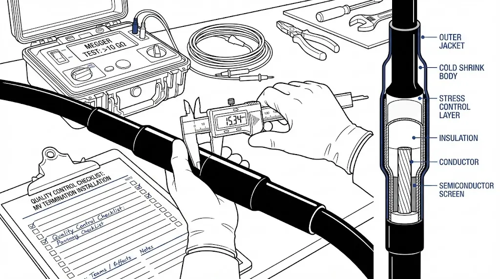
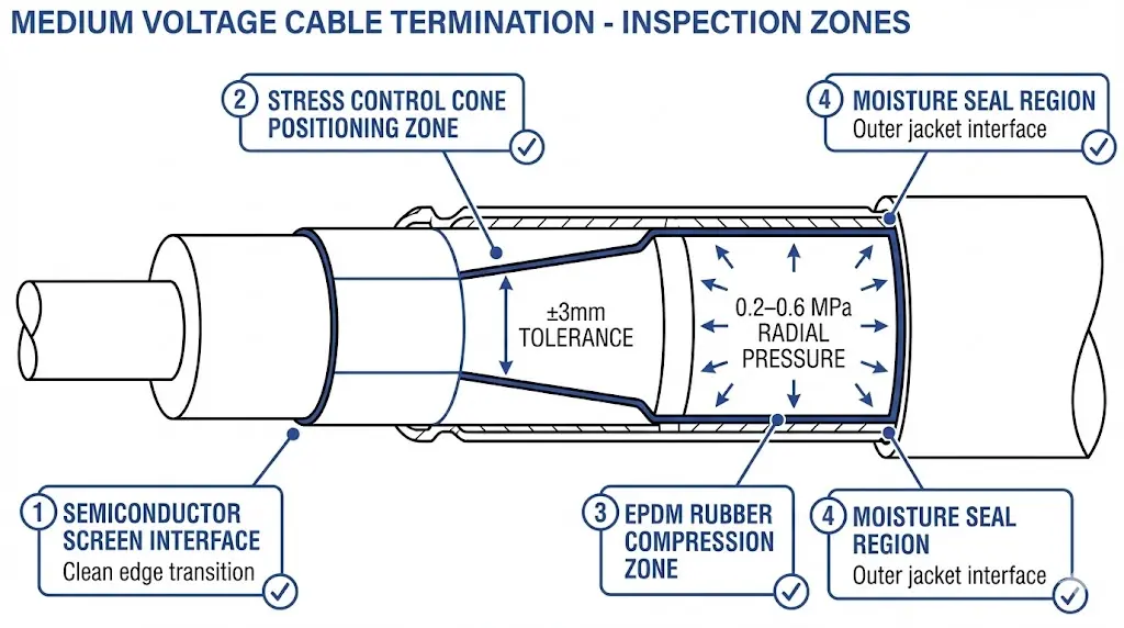
Figure 1. Medium voltage termination cross-section highlighting quality-critical inspection zones: semiconductor screen interface, stress cone positioning (±3 mm tolerance), EPDM compression zone (0.2–0.6 MPa), and moisture seal region.
[Expert Insight: Field Failure Patterns]
Coastal installations face salt contamination; industrial sites contend with conductive dust; underground vaults accumulate moisture—each environment demands tailored contamination control
Failures typically manifest 18–36 months post-installation, well after warranty verification but directly traceable to installation conditions
Thermal cycling between 20°C and 90°C conductor temperature accelerates degradation at installation defect sites, potentially reducing service life from 30+ years to under 5 years
Pre-Installation Verification Checklist
Quality control begins before the cable accessory leaves storage. Material receiving inspection catches defects when replacement remains simple.
Incoming Material Inspection:
Inspection Item
Acceptance Criteria
Reject If
Package seal
Intact, no moisture evidence
Torn, wet staining visible
Silicone/EPDM components
No deformation, cuts, or creases
Permanent compression marks
Heat shrink tubes
Uniform diameter throughout
Partial pre-shrinkage evident
Instructions
Present, correct voltage class
Missing or wrong rating
Shelf life
Within expiration date
Adhesives beyond 24 months
Environmental Readiness Verification:
Installation environment directly impacts accessory performance. Verify ambient temperature between 5°C and 35°C—EPDM rubber components suffer permanent deformation outside this range. Humidity should remain below 75% RH; above this threshold, condensation risk increases substantially. Cable surface temperature must exceed dew point by at least 3°C.
Contamination control matters more than installers typically recognize. Establish a clean work zone. Remove metallic particles from nearby grinding or welding. Shield the work area from wind-blown dust. In coastal environments, even brief exposure during cable preparation creates salt contamination invisible to the eye but detectable during PD testing weeks later.
Cable Preparation Quality Checkpoints
Cable preparation determines 60% of installation success. Dimensional errors and surface contamination at this stage propagate into permanent defects.
Dimensional Requirements:
Voltage Class
Screen Cut-Back
Insulation Exposure
Tolerance
6.6kV–11kV
20–25 mm
Per accessory datasheet
±2 mm
15kV–22kV
25–30 mm
Per accessory datasheet
±2 mm
33kV
30–40 mm
Per accessory datasheet
±2 mm
Use steel rulers and calipers—estimation causes errors. Mark dimensions before cutting. Double-check measurements before proceeding to semiconductor removal.
Semiconductor Layer Removal:
The semiconductor screen, with surface resistivity typically 10³–10⁶ Ω/square, must be completely removed from the insulation exposure zone while maintaining intimate contact with stress control elements at the transition. This balance requires careful technique.
Score the semiconductor layer circumferentially at the cut-back point using the cable manufacturer’s recommended tool. Avoid scoring deeper than 0.1 mm into the XLPE insulation—deeper cuts create stress concentration points. Remove semiconductor material completely; residue creates conductive paths along the stress control interface.
Insulation Surface Preparation:
Clean the exposed XLPE surface with lint-free cloth and manufacturer-approved solvent. Perform the white cloth test: wipe the surface with a clean white cloth and inspect for discoloration. Any visible contamination requires additional cleaning.
Time matters. Maximum exposure window between cleaning and accessory installation should not exceed 30 minutes in normal conditions, less in dusty or humid environments.
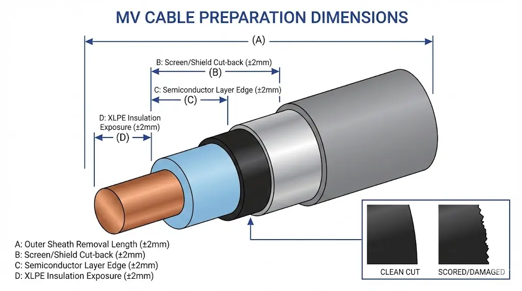
Figure 2. Cable preparation dimensional requirements for MV accessories installation showing critical measurements A through D with ±2 mm tolerances at semiconductor screen cut-back and insulation exposure zones.
Cold Shrink Installation Inspection Protocol
Cold shrink technology relies on pre-expanded EPDM or silicone rubber tubes that contract onto the cable when the support core is removed. Installation success depends on proper sizing, positioning, and core removal technique.
Pre-Installation Component Verification:
Confirm tube inner diameter matches cable outer diameter within the specified range—typically allowing 15–25% stretch. Verify stress control elements are correctly oriented. Check that mastic sealant strips are present and pliable.
Installation Sequence Checkpoints:
Step
QC Checkpoint
Pass Criteria
1
Stress cone positioning
Centered on semiconductor edge ±3 mm
2
Tube alignment
Concentric with cable axis
3
Core removal initiation
Smooth, continuous unwinding begins
4
Core removal completion
Full extraction without tube distortion
5
Interface inspection
No visible air gaps, wrinkles, or ridges
Core Removal Technique Assessment:
Remove the support core using steady, continuous rotation. Jerky or interrupted extraction causes tube distortion and potential air void formation. The tube should collapse smoothly onto the cable surface.
Post-Installation Tactile Test:
Run a gloved finger along the cold shrink tube surface. Any discontinuity, ridge, or soft spot indicates potential interface void requiring investigation before energization. EPDM rubber requires minimum radial compression of 0.3 MPa to achieve rated moisture sealing—insufficient compression permits moisture ingress that degrades insulation resistance within 18–24 months.
ZeeyiElec’s cold shrink cable accessories include installation guides with QC checkpoints specific to each voltage class and cable diameter range.
Heat Shrink Installation Inspection Protocol
Heat shrink accessories depend on controlled thermal activation to achieve proper recovery and adhesive seal formation. Temperature management determines success.
Heating Equipment Verification:
Confirm torch type matches manufacturer requirements—propane, butane, or hot air gun each produce different heat profiles. Verify adequate fuel supply for complete installation. Temperature indicators (infrared thermometer or heat crayons) should be available.
Temperature Control Parameters:
Material Type
Minimum Shrink Temp
Optimal Range
Maximum Safe Temp
Crosslinked polyolefin
90°C
110–120°C
150°C
Adhesive-lined tubes
100°C
120–130°C
160°C
Apply heat using the manufacturer-specified pattern—typically center-out for terminations, end-to-end for joints. Maintain consistent torch distance. Watch for these indicators:
Underheating signs: Incomplete recovery, tube does not conform tightly to cable contours, adhesive remains unexpressed at tube ends.
Overheating signs: Discoloration, surface bubbling, material becoming brittle, adhesive charring.
Shrink Recovery and Seal Verification:
The completed tube should conform tightly without visible gaps or bridging. Visible adhesive squeeze-out at tube ends confirms proper seal formation—absence of this bead indicates potential incomplete heating despite acceptable visual appearance of the tube body.
Heat shrink products from ZeeyiElec’s heat shrink cable accessories range include temperature indicator labels for field verification.
[Expert Insight: Heat Shrink Field Observations]
Ambient temperature below 10°C significantly increases heating time requirements—preheat the cable surface before applying heat shrink tubes in cold conditions
Wind creates uneven heating; shield the work area or adjust technique to compensate
Electrical testing provides objective verification that installation quality meets operational requirements. These tests detect defects invisible to visual inspection.
Insulation Resistance Testing Protocol:
Apply DC test voltage appropriate to system voltage class. Record readings at 1 minute for acceptance evaluation; extend to 10 minutes for polarization index calculation if assessing aged cables.
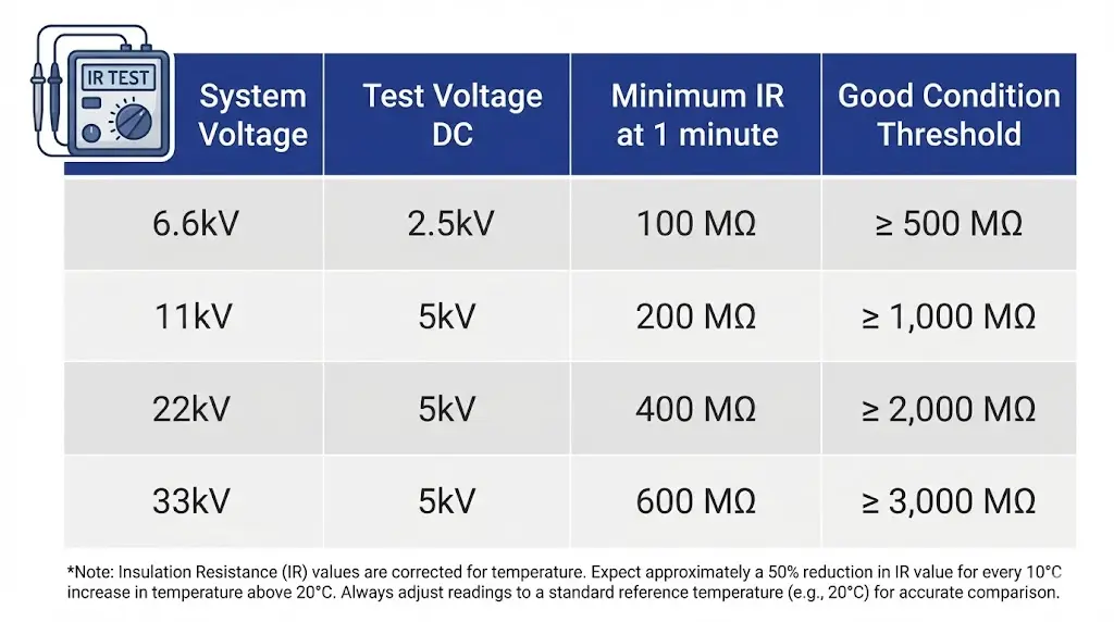
Figure 3. Insulation resistance test parameters by system voltage class showing DC test voltage selection and minimum acceptable IR values at 1-minute reading with temperature correction notes.
System Voltage
Test Voltage (DC)
Minimum IR (1 min)
Good Condition
6.6kV
2,500 V
100 MΩ
>1,000 MΩ
11kV
5,000 V
200 MΩ
>2,000 MΩ
22kV
5,000 V
400 MΩ
>5,000 MΩ
33kV
5,000 V
500 MΩ
>5,000 MΩ
Temperature affects readings significantly. Apply correction factors: approximately 50% reduction in IR per 10°C increase above the 20°C reference baseline.
Partial Discharge Measurement:
Field-portable PD detectors with sensitivity below 5 pC can identify installation defects before energization. According to IEEE 48-2020, field-installed terminations should demonstrate PD levels below 5 pC at 1.5 × U₀. Readings exceeding 10 pC warrant investigation and potential reinstallation.
High Voltage Withstand Considerations:
DC withstand testing on XLPE cables remains controversial—trapped charges may create stress points promoting future failures. Many utilities now prefer VLF (very low frequency) AC testing at 0.01–0.1 Hz for field commissioning per IEEE 400-2012 guidance. Test voltages typically reach 3 × U₀ for 15–30 minutes duration.
Common Installation Defects and Prevention
Field experience across varied installation environments reveals consistent defect patterns. Understanding causes enables prevention.
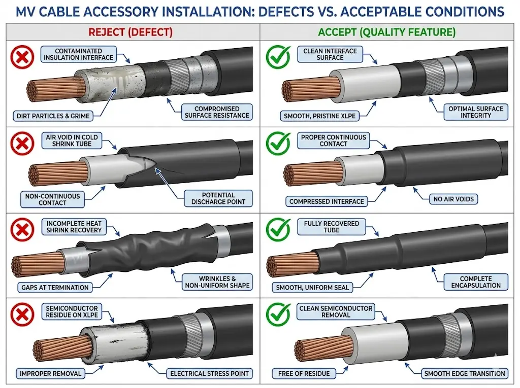
Figure 4. Installation defect identification guide comparing reject conditions (contamination, air voids, incomplete shrink, semiconductor residue) with acceptable installation quality for MV cable accessories.
Defect Type
Root Cause
Prevention
Detection Method
Interface contamination
Inadequate cleaning, dust exposure
Clean zone discipline, immediate assembly
PD test, visual if severe
Semiconductor residue
Incomplete removal, wrong technique
Proper tools, pre-assembly inspection
Visual, IR anomaly
Air voids (cold shrink)
Undersized tube, jerky core removal
Correct sizing, steady extraction
PD test, tactile inspection
Incomplete shrink (heat shrink)
Insufficient heating, wrong pattern
Temperature monitoring, correct technique
Visual, dimensional check
Insulation damage
Scoring too deep, handling damage
Proper tools, cable support
Visual, IR test anomaly
Incorrect dimensions
Measurement error, wrong datasheet
Double-check, use cutting guides
Pre-assembly verification
Documentation of all inspections creates traceability for warranty compliance and provides baseline data for future maintenance assessments.
Ensure Long-Term Reliability with Quality MV Accessories
Installation quality control transforms cable accessories from potential failure points into reliable system components. The checklist approach—systematic verification at each critical stage—reduces commissioning failures by approximately 35% compared to informal inspection methods.
Quality accessories support installation success. Products engineered with appropriate dimensional tolerances, clearly marked positioning guides, and comprehensive installation documentation reduce workmanship errors.
ZeeyiElec’s cable accessories range includes detailed installation guides, QC checkpoint documentation, and technical support for complex installations across 6.6kV to 33kV applications.
Download the complete 45-point QC checklist for field use, or contact our technical team for installation guidance on specific applications.
Frequently Asked Questions
Q: What is the most common cause of MV cable accessory failure after installation?
A: Interface contamination during cable preparation causes the largest share of failures—particles as small as 50 μm create partial discharge inception sites that progressively erode insulation over 18–36 months until complete breakdown occurs.
Q: How soon after installation should electrical testing be performed?
A: Insulation resistance and partial discharge testing should occur immediately after installation completion and before backfilling or enclosure closure, with follow-up testing recommended within 30 days of initial energization to establish baseline values.
Q: What ambient temperature range is acceptable for installing cold shrink accessories?
A: Most manufacturers specify 5°C to 35°C for cold shrink installation; below this range EPDM rubber stiffens and may not achieve adequate compression, while above 35°C the pre-stretched tube may begin relaxing before positioning is complete.
Q: How can I verify adequate heating during heat shrink installation without an infrared thermometer?
A: Temperature-indicating crayons or labels applied to the tube surface provide reliable indication—the crayon mark changes color or the label transforms when target temperature is reached, confirming proper adhesive activation.
Q: What polarization index value indicates moisture contamination in a newly installed accessory?
A: Polarization index values below 1.5 (calculated as 10-minute IR reading divided by 1-minute reading) suggest moisture presence or severely degraded insulation; newly installed accessories in good condition typically show PI values between 2.0 and 4.0.
Q: Should partial discharge testing be performed on every MV accessory installation?
A: While PD testing provides the most definitive quality verification, it requires specialized equipment not always available in field conditions; at minimum, perform PD testing on critical circuits, first-time installers’ work, and any installation where visual inspection reveals potential concerns.
Q: How long should cable surfaces be exposed between cleaning and accessory installation?
A: Maximum exposure time should not exceed 30 minutes under normal conditions; in dusty, humid, or contaminated environments, reduce this to 15 minutes or less, and re-clean if delays occur.
yoyo shi
Yoyo Shi writes for ZeeyiElec, focusing on medium-voltage accessories, transformer components, and cable accessory solutions. Her articles cover product applications, technical basics, and sourcing insights for global electrical industry buyers.