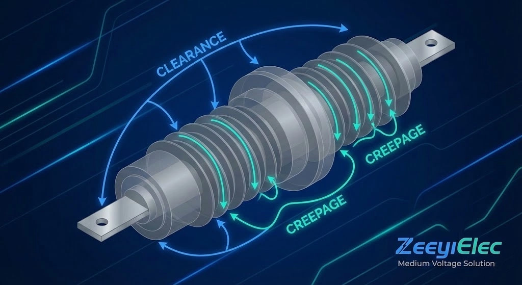
In the design of medium-voltage (MV) distribution networks, insulating components like transformer bushings serve as the critical interface between energized conductors and grounded enclosures. To prevent dielectric breakdown, engineers rely on two fundamental spatial parameters: clearance and creepage. Clearance is defined as the shortest distance through air between two conductive parts—the “strike distance” that prevents a direct flashover. Creepage is the shortest distance along the surface of an insulating material between two conductive parts. While both metrics aim to isolate high-voltage potentials, they address different physical failure mechanisms.
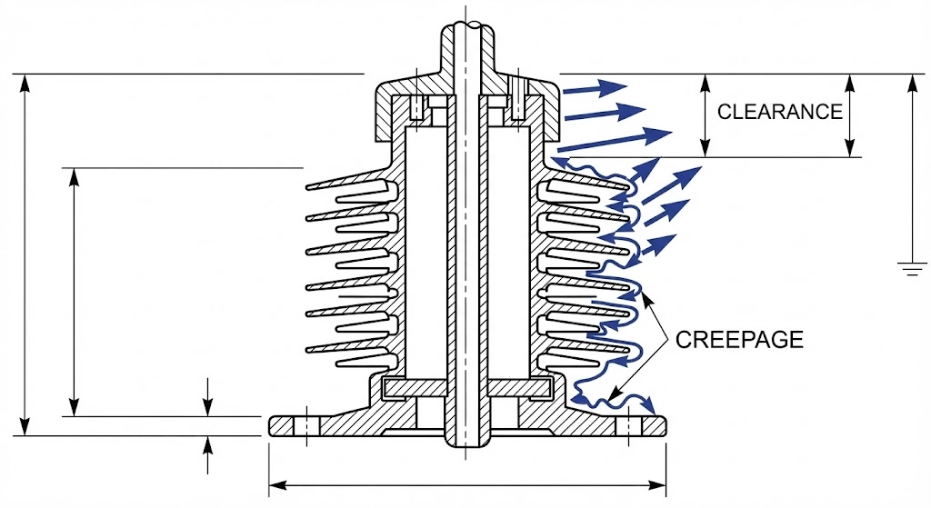
Figure 01: Geometric breakdown of the direct air path strike distance versus the contoured surface path over inorganic porcelain sheds.
Distinguishing Strike Distance from Surface Path
The primary role of clearance is to withstand transient overvoltages, such as lightning strikes or switching surges. For a standard 15kV system, the minimum clearance must be adjusted based on the Basic Insulation Level (BIL) of the equipment. Creepage is designed to combat “tracking”—the formation of conductive carbonized paths on the insulator surface caused by moisture and dust. Consequently, the creepage distance is always significantly longer than the clearance distance to provide a higher resistive barrier against leakage currents.
The Role of Bushing Sheds in Insulation
To maximize creepage without creating excessively tall medium voltage bushings, manufacturers utilize a “shed” or “skirt” geometry. These undulations increase the total surface area significantly. For example, a bushing with a physical height of only 300mm can achieve a total creepage path of 450mm or more by integrating deep sheds. This design is vital for cable accessories where space inside switchgear is limited. Neglecting the ratio between these distances often results in surface failures even when the air gap holds.
In practice, the relationship between these distances is governed by the equipment voltage class (Um). For a 24kV system, typical engineering requirements include:
Minimum Clearance (Air): ≥ 220 mm
Minimum Creepage (Surface): ≥ 500 mm (based on 20 mm/kV ratio)
Creepage Factor (CF): Creepage / Clearance > 1.0
[Expert Insight: Insulation Selection]
Creepage-to-Clearance Ratio: Target a ratio > 2.0 for outdoor MV installations to account for unpredictable surface pollution.
Geometric Efficiency: Deep, thin sheds are more effective at breaking continuous water films than shallow, thick undulations. * Standard Alignment: Verify if your project requires ANSI or DIN profiles early, as shed geometry varies significantly between these standards.
Physics of Surface Tracking and Air Breakdown
Air breakdown and surface tracking represent the two primary failure modes that creepage and clearance dimensions are engineered to prevent. Air breakdown occurs when the electric field strength exceeds the dielectric strength of air, approximately 3 kV/mm under standard conditions, leading to a flashover. Surface tracking is a progressive degradation mechanism that occurs over time as contaminants create conductive paths.
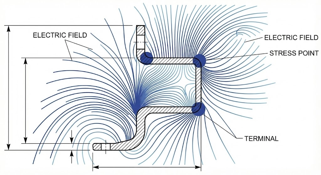
Figure 02: Simulation of electric field stress concentration at the bushing triple-point, highlighting areas prone to corona discharge and tracking.
Electric Field Concentration at Bushing Interfaces
Electric field stress concentrates at “triple points”—areas where the conductor, solid insulation, and air meet. If clearance is insufficient, these high-stress zones can ionize the air, creating corona discharge. This lowering of the effective insulation can trigger a flashover below the rated BIL.
The Mechanism of Dry Band Arcing
As dry bands form, the total system voltage drops across these narrow gaps, causing localized arcing. This process is described by:
+1
Voltage Gradient (E): E = V / d (where d is the dry band width)
Leakage Current (IL): IL ∝ σ × (V / Lcreep)
Where σ represents surface conductivity and Lcreep is the total creepage length. Increasing the creepage distance reduces IL, preventing fault evolution.
Systematic diagnosis shows that 15 kV cold shrink terminations failing at month fourteen often trace back to these micro-arcs carbonizing the surface. For authority, engineers reference IEC 60112, which defines the Comparative Tracking Index (CTI). [NEED AUTHORITY LINK SOURCE] anchor text: IEC 60112 Method for the determination of the proof and the comparative tracking indices.
Voltage Class and Minimum Distance Mapping
The selection of creepage and clearance is dictated by the system’s maximum operating voltage ($U_m$) and environmental severity. Transformer accessories must withstand both power-frequency voltages and transient surges.
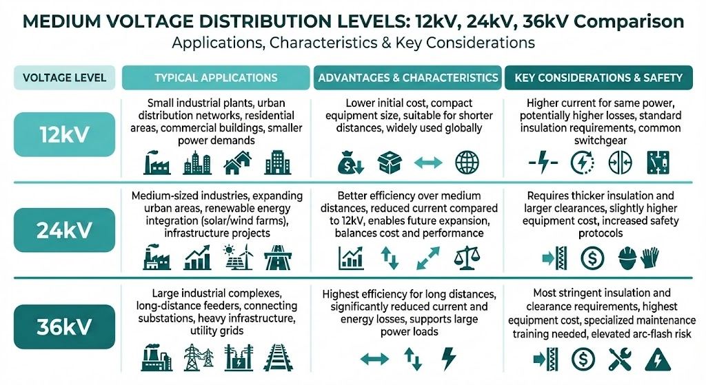
Figure 03: Engineering reference table mapping system voltage classes to required BIL, minimum clearance, and high-pollution creepage distances.
BIL (Basic Insulation Level) Requirements
BIL defines insulation strength against $1.2/50$ $\mu s$ impulse waves. A 15 kV system must often withstand a BIL of 95 kV or 110 kV, requiring clearances of 160 mm to 190 mm. Mismatches in these specifications account for roughly 40% of procurement errors.
Rated Current vs. Insulation Diameter
Voltage dictates the insulation path length, while rated current—ranging from 55 A to 3150 A—influences the core diameter.
Standard Parameters for MV Bushing Selection
System Voltage ($U_m$)
BIL (Impulse Peak)
Min. Clearance (Air)
Min. Creepage (Heavily Polluted)
12 kV
75 kV / 95 kV
120 mm – 160 mm
~372 mm
24 kV
125 kV / 150 kV
220 mm – 280 mm
~744 mm
36 kV
170 kV / 200 kV
320 mm – 380 mm
~1116 mm
Material Science: Porcelain vs. Epoxy vs. Resin
Material choice determines dielectric strength and tracking resistance. Low-voltage (LV) secondary bushings serving circuits up to 1 kV often use HTN (High Temperature Nylon) or specialized resins.
Dielectric Strength and Thermal Stability
In the 12 kV to 52 kV range, porcelain is the industry standard for outdoor medium voltage bushings due to UV resistance. Epoxy resin offers precision for bushing well inserts but requires specific formulation to prevent outdoor “chalking”.
Material Performance Characteristics
Material Type
Dielectric Strength
Pollution Resistance
Common Application
Porcelain (C110/C120)
15–20 kV/mm
Excellent (Glazed)
Outdoor MV Transformers
Epoxy / Resin
25–35 kV/mm
Moderate to High
Indoor Switchgear & Wells
HTN (Nylon)
10–15 kV/mm
Low (Indoor)
LV Secondary Terminals
Environmental Factors and Pollution Levels
Creepage distances must be scaled by environmental severity. In coastal zones, ratios can reach 31 mm/kV. Altitude also impacts strike distance.
For installations above 1,000 meters, a derating factor (Ka) must be applied to clearance (d):
Ka Calculation: Ka = em(H-1000)/8150
Standard Range: At 2,000 meters, clearance must increase by ≈12-15%.
[Expert Insight: Environmental Hardening] * Cold Shrink Advantages: Use cold shrink cable accessories in high-humidity zones; the radial pressure maintains an active seal. * Periodic Maintenance: Schedule annual cleaning in heavy dust areas to remove conductive layers before dry-band arcing occurs.
Field Selection and Compatibility Checklist
Selecting the correct bushing requires matching 15–25 parameters. In pad-mounted transformers, coordination between the bushing well and bushing well inserts is critical to prevent partial discharge.
Critical Specification Checklist
Category
Required Parameter
Typical MV Range
Electrical
Voltage Class ($U_m$)
12 kV – 52 kV
Electrical
Current Rating
55 A – 3150 A
Mechanical
Mounting Hole Dia.
ANSI/DIN standard
Procurement Support for MV Accessory Projects
Successful procurement of medium-voltage transformer accessories and cable accessories relies on precise technical alignment. ZeeyiElec provides a systematic framework to eliminate the specification gaps that cause 30–40% of site rejections.
Ready to discuss your requirements? Contact Yoyo Shi at +86 150 5877 8024 or email [email protected] for a response within 24 hours.
Frequently Asked Questions
What is the standard creepage distance for a 15kV bushing?
For 15kV bushings, creepage typically ranges from 300mm to 480mm depending on pollution levels. Heavily contaminated environments require the higher distance to prevent tracking faults.
How does altitude affect MV bushing clearance?
Above 1,000 meters, clearances must increase by roughly 1% for every 100 meters of elevation. This adjustment accounts for the lower dielectric strength of air at reduced pressures.
Can I use an indoor-rated bushing in an outdoor MV cabinet?
No, indoor bushings lack the shed geometry required to break conductive moisture paths. Outdoor exposure often leads to surface tracking and failure within the first year.
Why is creepage distance always longer than clearance distance?
Creepage follows the actual physical surface of the insulator, including all sheds and ribs. Clearance is a direct “strike” path through air, making it naturally shorter than the surface path.
What happens if the bushing creepage is insufficient for the environment?
Insufficient creepage allows leakage currents to form dry bands and localized arcing. Over time, this results in permanent carbon tracking and catastrophic insulation breakdown.
How do I determine the pollution level for my project site?
Pollution levels are classified from Light to Very Heavy based on coastal proximity or industrial dust presence. Engineering standards like IEC 60815 define the specific mm/kV ratios required for each.
yoyo shi
Yoyo Shi writes for ZeeyiElec, focusing on medium-voltage accessories, transformer components, and cable accessory solutions. Her articles cover product applications, technical basics, and sourcing insights for global electrical industry buyers.