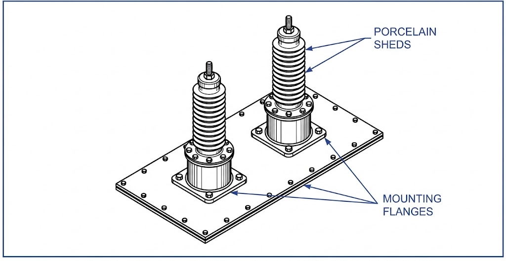
Introduction: The Role of MV Bushings in Transformer Reliability
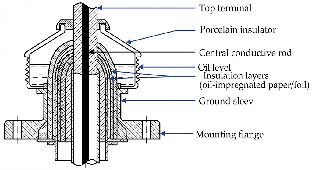
Figure 01:A cross-sectional view illustrating the internal conductor, insulation grading, and the critical oil-to-air interface managed by the mounting flange.
The Core Function of an MV Bushing
A medium voltage bushing is a precision-engineered insulated pass-through device. Its fundamental purpose is to safely route high-voltage current from the internal windings of a transformer, through the grounded metal tank wall, and out to the overhead distribution grid or enclosed switchgear. Without advanced dielectric stress management, the proximity of the live conductor to the grounded tank would immediately result in a catastrophic short circuit.
To prevent flashovers, the bushing establishes a controlled oil-to-air interface boundary. It utilizes a central conductive rod—typically machined from high-conductivity copper or aluminum—encased within a robust insulation body. A grounded mounting flange secures the assembly to the transformer tank, utilizing high-performance elastomer gaskets to maintain a hermetic seal that prevents dielectric fluid from leaking out and environmental moisture from seeping in. are engineered to support system voltage classes ranging from 12 kV up to 52 kV, while simultaneously carrying continuous current ratings that span from 250 A to 3150 A depending on the transformer’s specific MVA rating.
While a transformer’s core and windings remain protected within a sealed, fluid-filled environment, bushings are subjected to punishing conditions on two fronts. The lower section remains submerged in hot insulating oil, while the upper external sheds face ultraviolet radiation, severe weather, and atmospheric pollution. This dual-exposure reality makes the bushing one of the most electrically and mechanically stressed components on the distribution network.
For distribution systems operating at voltages ≤ 52 kV, the bushing acts as the primary barrier against grid-side transient overvoltages. For example, a standard 15 kV class unit is engineered to withstand a Basic Impulse Level (BIL) of at least 95 kV. During peak loading, the core conductor must also manage severe thermal gradients, frequently experiencing a ΔT of 40°C to 55°C between the internal transformer oil and the external ambient air.
If an engineer specifies a bushing with inadequate creepage distance or insufficient mechanical cantilever strength, the insulation structure will prematurely degrade. Selecting the correct component parameters safeguards the entire substation’s operational lifespan, aligning with overarching grid safety frameworks like [NEED AUTHORITY LINK SOURCE: IEEE Std C57.19.00 – General Requirements for Power Apparatus Bushings].
Standard Systems: ANSI vs. DIN Specifications
When procuring medium voltage bushings, the fundamental division in component architecture stems from regional standard frameworks. Selecting the wrong standard creates an absolute mechanical and electrical mismatch at the transformer tank interface. The choice between ANSI and DIN formats dictates everything from the external terminal geometry to the mounting flange bolt circle.
ANSI Bushings: North American Grid Standards
ANSI (American National Standards Institute) and IEEE frameworks govern power distribution infrastructure across North America and regions adopting US engineering practices. ANSI-style bushings are characterized by their specific external connection methods, frequently utilizing threaded studs, spade terminals, or specialized draw-lead mechanisms.
[VERIFY STANDARD: IEEE Std C57.19.01 defines the dimensional and electrical requirements for these apparatus bushings.] Under this standard, are classified by standard voltage tiers—such as 15 kV, 25 kV, and 34.5 kV—and matched with continuous current ratings starting at 200 A for distribution applications.
DIN Bushings: IEC/European Design Logic
DIN (Deutsches Institut für Normung) bushings adhere to European engineering philosophies and are globally harmonized with IEC specifications, particularly IEC 60137. These bushings dominate European, Middle Eastern, and major Asian markets.
They are recognizable by their metric hardware, smooth flag terminals, and standardized porcelain dimensions. Voltage classes follow the IEC progression—commonly 12 kV, 24 kV, and 36 kV—with current ratings categorized in strict steps from 250 A to 3150 A. Flanges rely on standard metric bolt patterns prioritizing uniform clamping force.
Identifying Dimensional and Interface Mismatches
The most frequent procurement error involves specifying a DIN bushing for an ANSI-machined transformer tank, or vice versa. The physical dimensions are completely incompatible. A mismatch of even ±2 mm in the bolt circle diameter (∅) or an angular deviation of ≤ 5° on the mounting flange will prevent the gasket from seating properly. Attempting to force the installation will over-compress the nitrile or cork gasket, inevitably leading to insulating oil leaks and moisture ingress.
Expert Insight: Avoiding Standard Clashes
Never assume the bushing standard matches the transformer’s origin; an IEC transformer might require ANSI bushings for a specific North American deployment.
Always verify the terminal thread type (e.g., metric M12 versus imperial 1/2-13) before finalizing the RFQ to prevent on-site cable connection failures.
Require explicit technical drawings during the vendor submittal phase to confirm the flange bolt circle matches the tank machining perfectly.
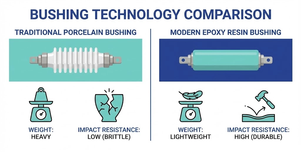
Material Types: Porcelain vs. Epoxy Cast Resin
Figure 02:Epoxy cast resin bushings offer significant structural advantages over traditional porcelain, including reduced weight and enhanced shatter resistance during transport.
Once the standard is established, the next critical variable is the insulation material. Medium voltage transformer bushings are primarily manufactured from either traditional high-voltage porcelain or advanced epoxy cast resin. The selection is driven by project realities—including environmental exposure, mechanical stress, and transportation logistics.
Porcelain Bushings: The Traditional Standard
For decades, glazed porcelain has been the default material for both ANSI and DIN bushings in outdoor substation environments. Porcelain offers unmatched resistance to ultraviolet degradation, making it highly reliable for direct sunlight exposure over a 30- to 40-year lifespan. It is inherently fire-resistant and provides excellent surface tracking resistance under heavy environmental pollution.
However, porcelain is fundamentally a brittle ceramic. If a distribution transformer with pre-installed porcelain bushings experiences severe shock during ocean freight or rough handling during a crane lift, the sheds can easily chip or shatter. A cracked porcelain shed instantly compromises creepage distance, requiring total unit replacement before energization.
Epoxy Resin Bushings: Modern Structural Advantages
Epoxy cast resin—specifically cycloaliphatic epoxy (CEP)—has rapidly gained market share as the modern alternative, particularly for indoor applications or integrated switchgear enclosures. The primary advantage of epoxy resin is high mechanical strength and impact resistance. These bushings are effectively shatterproof, drastically reducing transit damage and site rejection rates.
Furthermore, epoxy bushings are significantly lighter than their porcelain equivalents, often weighing ≤ 40% less for the same voltage class. This weight reduction directly translates to less mechanical stress on the transformer tank mounting flange, especially for larger units operating at 36 kV or 52 kV.
Environmental Drivers for Material Selection
For outdoor utility substations subjected to heavy UV exposure, glazed porcelain remains the preferred choice. Conversely, for or medium voltage applications housed inside compact secondary substations (CSS), pad-mounted enclosures, or areas prone to high seismic activity, epoxy resin is the superior engineering choice. The structural integrity of epoxy minimizes the risk of catastrophic mechanical failure during an earthquake or a handling error on a constrained site.
Key Electrical Parameters for Selection
Defining the mechanical footprint is only half the procurement equation. The electrical specifications determine whether the bushing can survive the daily realities of the distribution network. Navigating this selection process requires matching three foundational parameters to exact grid conditions.
System Voltage and Basic Impulse Level (BIL)
The system voltage dictates the primary insulation thickness, but the Basic Impulse Level (BIL) defines the bushing’s ability to survive transient overvoltages.
For example, a transformer operating on a 24 kV distribution network typically requires a bushing with a BIL of ≥ 125 kV. Specifying an inadequate BIL means the next lightning storm could easily arc across the bushing sheds to the grounded tank, bypassing internal protection and tripping the local network.
Continuous Current Rating and Thermal Limits
Current ratings dictate the cross-sectional area of the central conductor. Standard medium voltage ratings scale from 250 A up to 3150 A for heavy industrial applications.
Field failures frequently occur when procurement teams fail to account for future load growth or harmonic heating. If a bushing strictly rated for 630 A is consistently pushed to 800 A during peak summer load cycles, the internal conductor generates excessive I²R losses. This localized heating pushes the temperature rise (ΔT) beyond design limits, degrading nitrile flange gaskets and resulting in inevitable oil leaks.
Creepage Distance and Pollution Severity
Creepage is the shortest path along the outer corrugated surface from the live terminal to the grounded flange. Its length is dictated entirely by site pollution severity.
According to standard guidelines, a clean rural site may only require a specific creepage distance of 16 mm/kV. In heavy industrial zones or coastal environments, airborne salt and chemical dust settle on the sheds. Dampened by morning dew, this layer becomes highly conductive. To prevent phase-to-ground faults, engineers must specify a heavy-pollution creepage profile of ≥ 31 mm/kV.
Expert Insight: Specifying for the Real World
Always specify continuous current ratings at least 20% above the calculated maximum load to buffer against unexpected harmonic heating.
Treat 16 mm/kV creepage as an absolute minimum for clean sites; any industrial or coastal proximity demands ≥ 31 mm/kV.
Upgrading from a 95 kV BIL to 110 kV BIL on a 15 kV system is a low-cost insurance policy against frequent transient overvoltages.
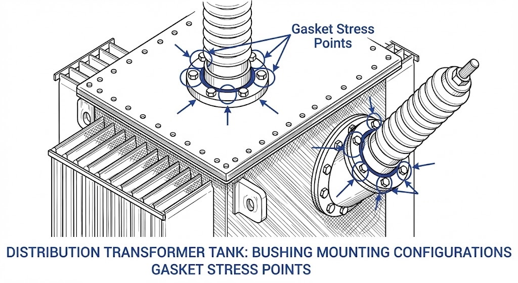
Field Conditions and Mounting Configurations
Figure 03:Sidewall-mounted bushings introduce asymmetric cantilever stress on flange gaskets, requiring precise torque sequencing to prevent dielectric fluid leaks.
A theoretically perfect bushing selection will fail if it cannot adapt to physical installation realities. Field conditions—ranging from the mounting angle to the atmospheric pressure—must dictate final mechanical and dielectric specifications.
Top-Mount vs. Sidewall-Mount Architectures
The orientation of the bushing on the transformer tank drastically alters its mechanical stress profile. Top-mounted bushings stand vertically, distributing weight evenly across the flange gasket. Sidewall mounting is frequently utilized in enclosed transformers to improve cable routing, often working in conjunction with dead-front .
When an MV bushing is installed at an angle—typically 15° to 45° off the vertical axis—the cantilever load creates asymmetric compression on the flange sealing system. If field crews fail to utilize a calibrated, alternating star-pattern torque sequence, the lower edge remains under-compressed. Over months of thermal cycling, this leads to dielectric fluid seepage down the exterior tank wall.
Altitude De-Rating Considerations
The dielectric strength of ambient air decreases as elevation increases, directly impacting external flashover resistance. Standard accessories are type-tested for installations at or below 1000 meters above sea level.
If a 35 kV distribution transformer is deployed to a high-altitude mining operation at 2500 m, reduced air density compromises the insulation boundary. Engineers must apply a dielectric de-rating factor, typically increasing the external strike distance by roughly 1% for every 100 m of elevation exceeding the 1000 m baseline. Procurement teams must often specify the next voltage class up (e.g., using a 52 kV bushing on a 35 kV system) purely to satisfy high-altitude clearance requirements.
Managing Heavy Pollution and Coastal Environments
In coastal environments, saline fog coats external sheds. While specifying a heavy-pollution creepage profile is the primary defense, field maintenance sometimes requires aggressive interventions. For installations experiencing repeated tracking faults, field engineers often apply Room Temperature Vulcanizing (RTV) silicone coatings over standard porcelain to restore hydrophobicity, forcing moisture to bead up rather than form conductive sheets.
Procurement Checklist for MV Bushings
Incomplete specifications account for a significant percentage of accessory mismatches during transformer assembly. To eliminate vendor clarification loops, procurement teams must provide a comprehensive dataset in their Request for Quotation (RFQ).
Essential RFQ Data Points
A standard procurement request must explicitly define both the electrical environment and the mechanical interface:
Standard System: Specify ANSI/IEEE or DIN/IEC format to ensure overarching physical compatibility.
Electrical Ratings: Define the system voltage, Basic Impulse Level (e.g., 24 kV / 125 kV BIL), and continuous current (e.g., 630 A or 1250 A).
Insulation Material: State the preference for traditional glazed porcelain or shatter-resistant epoxy cast resin.
Creepage Requirements: Provide the required specific creepage distance based on site pollution levels.
For clean environments: 16 mm/kV
For heavy contamination: ≥ 31 mm/kV
Mounting Geometry: Confirm the flange dimensions, exact bolt circle diameter, and whether the installation will be top-mounted or sidewall-mounted.
Field experience dictates that omitting a detail as simple as the flange bolt circle diameter can extend a standard two-week RFQ cycle into six weeks.
Sourcing Reliable MV Bushings with ZeeyiElec
Whether engineering a new substation layout or sourcing replacements, Wenzhou Zeeyi Electric Co., Ltd. provides precision-engineered components tailored to your grid parameters. From high-strength epoxy designs to standardized DIN porcelain models spanning 12 kV to 52 kV, our technical team supports your with rapid model matching, OEM/ODM configuration, and complete export documentation.
Frequently Asked Questions
What is the difference between a low voltage and medium voltage bushing?
Low voltage bushings serve secondary transformer circuits up to 1.2 kV, managing high load currents ranging from 600 A to over 5000 A, while medium voltage bushings handle primary grid connections from 12 kV to 52 kV at comparatively lower currents of 200 A to 3150 A. Structural complexity and internal dielectric thickness increase significantly for medium voltage applications to prevent high-voltage electrical breakdown.
How do I choose the right creepage distance for an MV bushing?
Specific creepage distance must be selected based on environmental pollution severity, typically starting at 16 mm/kV for clean rural environments and scaling up to 31 mm/kV for coastal or heavy industrial zones. Selecting an inadequate creepage profile allows conductive dust or saline layers to form, leading to rapid surface tracking and eventual phase-to-ground flashovers.
Can I replace a porcelain bushing with an epoxy cast resin bushing?
Replacing traditional porcelain with a modern epoxy resin bushing is a highly effective field retrofit, provided the new unit perfectly matches the original mounting flange bolt circle and external terminal hardware dimensions. The engineered replacement must also rigorously meet or exceed the original Basic Impulse Level (BIL) and continuous thermal current ratings to ensure long-term grid safety.
What is the standard BIL for a 15kV class transformer bushing?
A standard 15 kV class medium voltage bushing is typically engineered to withstand a baseline Basic Impulse Level (BIL) of 95 kV, which protects the transformer core from routine switching surges and grid transients. In geographical regions with extreme lightning exposure, utility engineers frequently over-specify this requirement to a 110 kV BIL design for added transient overvoltage protection margin.
Why do some MV bushings develop oil leaks at the mounting flange?
Dielectric fluid leaks at the tank interface almost always result from uneven bolt torque application during initial installation or the inevitable thermal degradation of standard nitrile gaskets after years of heavy load cycling. Utilizing high-temperature Viton replacement gaskets and strictly enforcing a calibrated, alternating star-pattern torque sequence prevents the asymmetric flange compression that directly causes these leaks.
At what altitude do medium voltage bushings require de-rating?
Standard medium voltage bushings require dielectric de-rating when installed at elevations exceeding 1000 meters above sea level due to the reduced insulating strength of thinner ambient air. Engineers must typically apply a de-rating factor that increases the external strike distance by approximately 1% for every 100 meters above the 1000-meter threshold.
yoyo shi
Yoyo Shi writes for ZeeyiElec, focusing on medium-voltage accessories, transformer components, and cable accessory solutions. Her articles cover product applications, technical basics, and sourcing insights for global electrical industry buyers.