In distribution transformer engineering, the distinction between Low Voltage (LV) and Medium Voltage (MV) bushings is defined primarily by the system voltage class and the resulting dielectric stress. While both components serve the same fundamental purpose—transferring current from internal windings through the grounded tank wall—their engineering boundaries are dictated by the physics of the operating environment.
Defining the Electrical Interface: 1 kV vs. 36 kV
The primary boundary for LV bushings is an operating limit of 1 kV, though they are often designed for a Rated Maximum Voltage of 1.2 kV or 3.0 kV to provide a safety margin. In contrast, MV bushings handle the 1 kV to 36 kV range, with common project specifications covering 12 kV, 24 kV, and 52 kV classes. This shift in voltage magnitude necessitates a move from simple insulation to complex stress management architecture.
Voltage Thresholds and Creepage Requirements
For an MV bushing rated at 24 kV with a Basic Insulation Level (BIL) of 125 kV, the creepage distance (the shortest path along the surface of the insulation) must be significantly higher than an LV equivalent to prevent tracking. According to IEC 60137 (Insulated bushings for alternating voltages above 1000 V), the minimum nominal creepage distance is calculated based on the Pollution Level (e.g., 25 mm/kV to 31 mm/kV for heavy pollution areas).
[NEED AUTHORITY LINK SOURCE: IEC 60137 Standard]
Current Density vs. Dielectric Stress
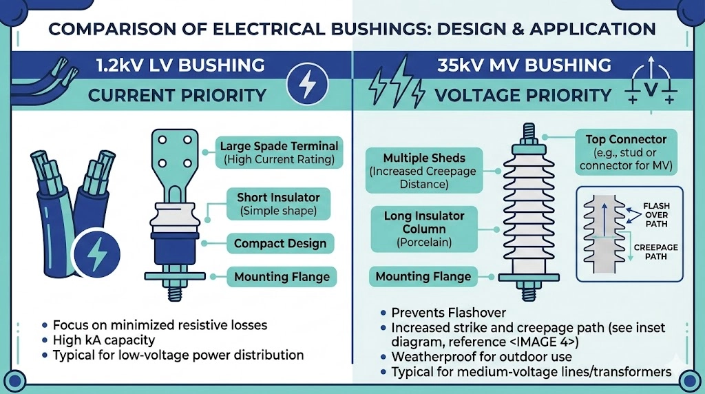
The engineering focus shifts dramatically at the 1 kV boundary. Low Voltage Bushings typically prioritize high-current stability, with ratings frequently reaching 600 A to 5000 A+. Because the voltage is low, the insulation thickness is minimized to favor thermal dissipation. Conversely, Medium Voltage Bushings handle lower continuous currents (55 A to 3150 A) but must withstand intense dielectric fields.
Expert Insight: Dielectric Integrity
Partial Discharge (PD) Sensitivity: MV bushings must be tested for PD levels; even micro-voids in epoxy can lead to failure at 35 kV. * BIL Verification: Always confirm the Basic Insulation Level (e.g., 95 kV or 125 kV) matches the transformer’s lightning impulse requirements. * Creepage Calculation: In coastal regions, ensure the bushing’s creepage distance accounts for salt-fog conductivity to prevent surface tracking.
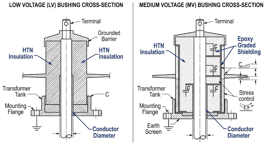
The Physics of Insulation: Material Composition and Dielectric Strength
At the engineering boundary between LV and MV, the choice of insulation material shifts from thermal management to dielectric field control. While LV bushings handle high-current transfer with minimal electrical stress, MV bushings must maintain structural integrity under continuous phase-to-ground potentials.
Material Performance Characteristics
High Temperature Nylon (HTN): Predominantly used for secondary LV bushings due to its excellent thermal stability under high-current loads.
Porcelain: The industry standard for outdoor MV applications, offering superior resistance to UV radiation and chemical tracking.
Epoxy Resin: Favored for indoor or dead-front MV applications because it allows for complex, void-free geometries that optimize the internal electric field.
Thermal Stability and Heat Dissipation
In high-current LV applications, $I^2R$ losses generate significant heat that the bushing must dissipate to prevent gasket degradation. LV designs often feature specialized polymers that maintain a UL 94 V-0 flame rating while supporting continuous operating temperatures exceeding 105°C. In contrast, MV bushing design focuses on minimizing internal ionization during BIL impulse events.
Figure 01:This scientific illustration details the transition from thin HTN thermal insulation in LV units to graded dielectric profiles in MV components.
Structural Architecture: High-Current LV vs. High-Voltage MV
The physical construction of a bushing is a direct reflection of its engineering priority. Both components serve as an insulated pass-through for transformer tank walls, but their internal architectures differ significantly.
Terminal Configurations for 600A to 5000A+
LV Terminals: Often feature spade-type connectors or multiple-hole busbar connections to accommodate large-gauge cables.
Current Ratings: LV bushings are specified in the 600A to 5000A+ range, requiring massive internal studs to minimize resistive heating.
MV Terminals: Typically utilize threaded studs or plug-in interfaces like Bushing Well & Inserts designed for 200A or 600A systems.
Mounting Constraints and Tank Wall Clearance
Dielectric Clearance: MV bushings (12kV–52kV) require specific minimum distances between the live conductor and the grounded tank wall to prevent internal arcing.
Gasket Surface: High-current LV bushings require larger mounting flanges to support the mechanical weight of heavy secondary cables.
Figure 02:Structural architecture mapping demonstrates how LV bushings prioritize conductor mass while MV bushings prioritize dielectric clearance distances
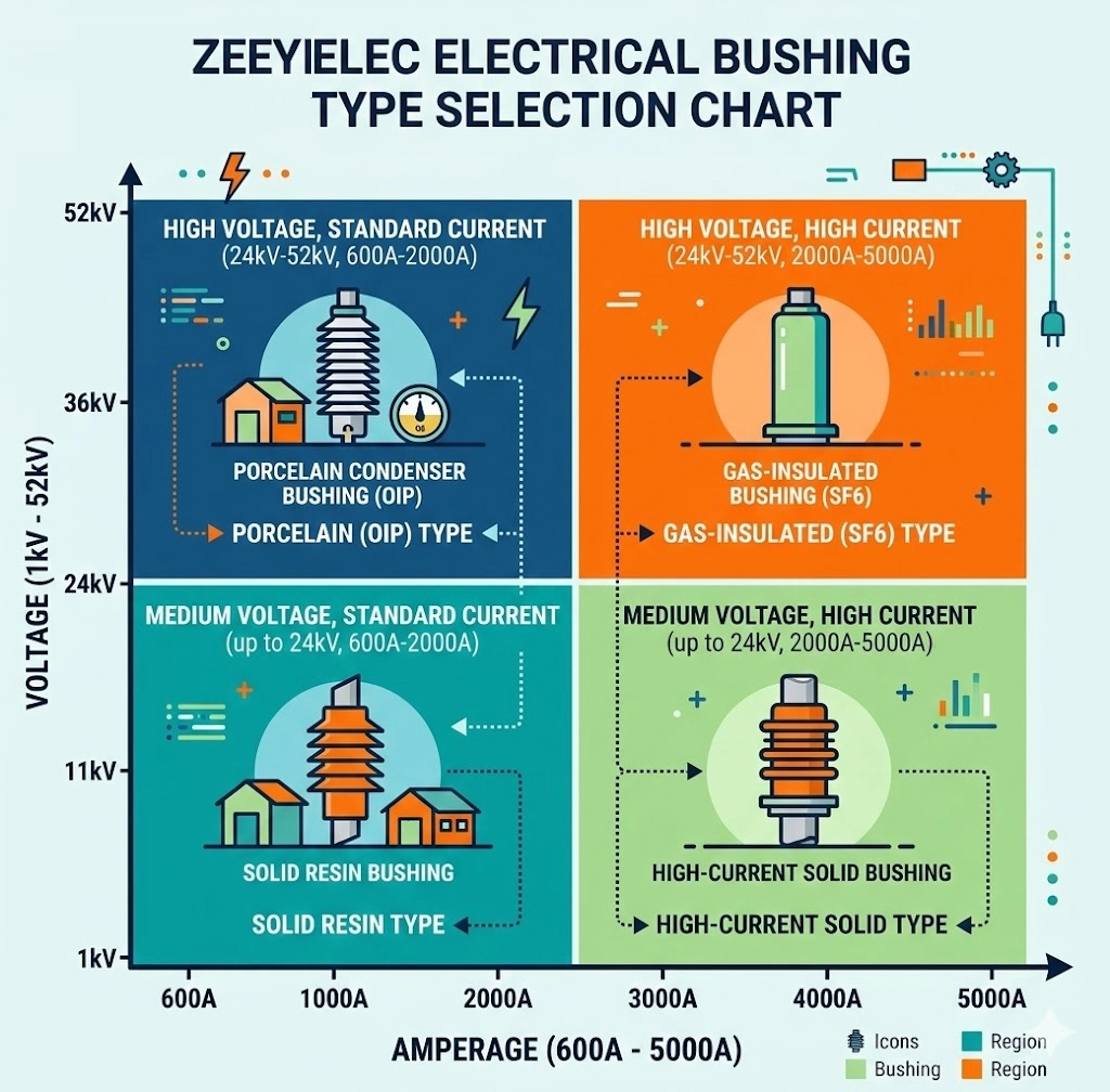
Application Matrix: Selecting the Right Bushing for the Environment
Choosing between LV and MV bushings requires evaluating environmental conditions and electrical demands. While system voltage is the primary filter, secondary factors often dictate long-term reliability.
Indoor vs. Outdoor Exposure Readiness
For outdoor utility applications, porcelain is preferred for MV bushings due to its UV resistance. In contrast, indoor industrial environments often utilize epoxy resin or high-performance polymers for more compact designs.
Compatibility with Bushing Well Inserts
In modern dead-front transformer designs, MV selection often involves Bushing Well & Inserts. These components provide a secure, insulated foundation for separable connectors, supporting 200A continuous current applications.
Expert Insight: Field Selection
* Standard Matching: Verify if the project requires ANSI porcelain or DIN porcelain to ensure tank hole compatibility. * Material Integrity: Use HTN for high-vibration environments where porcelain might crack. * Pollution Index: In industrial zones, specify MV bushings with extra-high creepage to prevent flashovers.
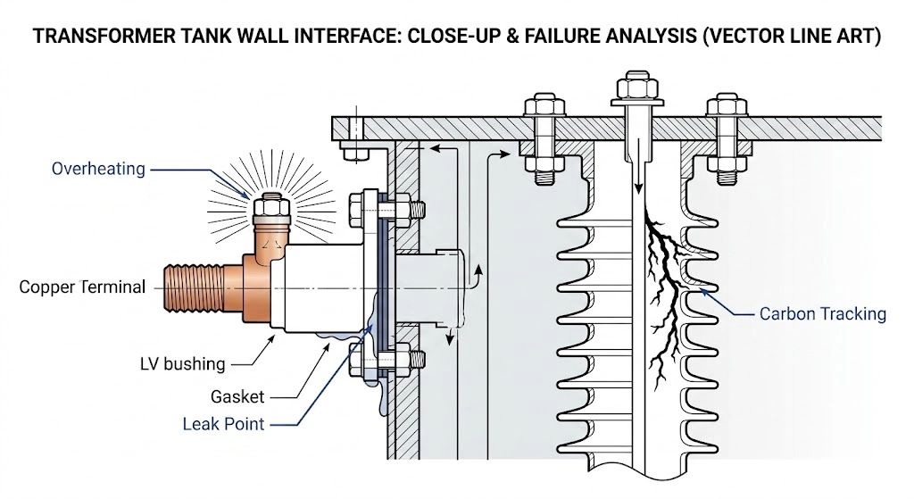
Field Realities: Installation and Interface Reliability
The engineering boundary extends into the physical rigors of field deployment. Accessories like bushings account for a disproportionate share of field failures, as they serve as interface points bridging internal insulation with external connections.
Common Failure Modes
Dielectric Breakdown: In MV systems, improper internal clearance can trigger partial discharge.
Thermal Stress: High-current LV applications generate heat; loose terminal connections lead to thermal runaway and gasket degradation.
Tracking: Surface contamination on MV bushings creates conductive paths, leading to flashovers if the creepage distance is insufficient.
Figure 03:Strategic identification of failure modes at the transformer interface where 15-25% of outages originate due to accessory malfunction.
Technical Comparison: LV vs. MV Engineering Summary
Parameter
Low Voltage (LV) Bushings
Medium Voltage (MV) Bushings
Voltage Class
Up to 1.2 kV
1 kV to 36 kV
Current Rating
600 A to 5000 A+
55 A to 3150 A
Primary Material
HTN, Resin, Porcelain
Porcelain, Epoxy
Primary Stress
Thermal (Heat dissipation)
Dielectric (Field grading)
Incomplete specifications for Transformer Accessories account for approximately 40% of component mismatches and costly change orders. Verification typically requires cross-referencing 15–25 distinct technical parameters before purchase order approval.
Streamline Your Procurement with Precision-Matched Accessories
A well-structured Request for Quotation for transformer accessories directly impacts procurement success. Our Transformer Accessories center provides a technical overview of critical interface components that support insulated connection and switching operations.
Whether you are specifying Medium Voltage Bushings for a utility grid or high-current Low Voltage Bushings for an industrial secondary, our team supports product selection and technical model matching.
24h Technical Response: Fast engineering feedback on your required specs and drawings.
Export Documentation Ready: Complete support for international shipping, including technical compliance certificates.
Frequently Asked Questions
Can a low voltage bushing be used for 5 kV applications?
No, LV bushings are strictly rated for systems up to 1 kV or 1.2 kV. Using them in 5 kV circuits would result in immediate dielectric breakdown because the creepage distance is insufficient to prevent arcing.
What is the primary material difference between LV and MV bushings?
LV bushings often utilize High Temperature Nylon (HTN) or Porous Resin for thermal stability, while MV bushings require Porcelain or high-grade Epoxy. This material shift is necessary to handle the increased dielectric stress found in 12 kV to 36 kV applications.
Why do MV bushings require specific ANSI or DIN standard matching?
MV bushings must interface with standardized transformer tank holes and external connectors that vary by regional utility requirements. Incorrect standard matching leads to equipment incompatibility, oil leaks, or improper electrical clearance.
How does current rating affect LV bushing design?
Since LV bushings often handle 600A to 5000A+, they require massive conductors and robust spade-type terminals to manage heat. The engineering focus is on maximizing thermal dissipation to prevent gasket failure rather than dielectric field grading.
Do MV bushings require more maintenance than LV versions?
Yes, MV bushings are more sensitive to surface contamination and moisture which can cause electrical tracking. Regular cleaning and gasket inspection of interface points like bushings and bushing well inserts are critical for maintaining system reliability.
yoyo shi
Yoyo Shi writes for ZeeyiElec, focusing on medium-voltage accessories, transformer components, and cable accessory solutions. Her articles cover product applications, technical basics, and sourcing insights for global electrical industry buyers.